1983 FIAT UNO radiator
[x] Cancel search: radiatorPage 246 of 303

Wiring diagrams 14•7
14
Wiring diagram 9 - windscreen wash/wipe, radiator fan, coolant
temperature sensor, heated rear screen and instrument panel illumination
Wiring diagram 10 - windscreen wash/wipe, radiator fan and coolant
temperature sensor (Comfort and ES models)
Page 256 of 303
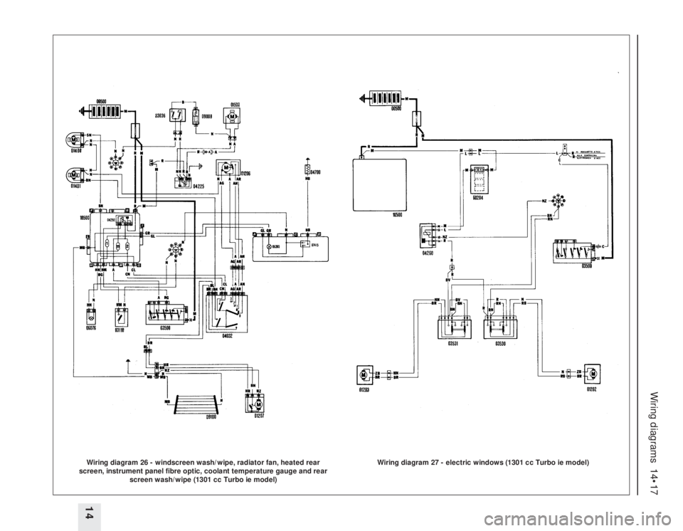
Wiring diagrams 14•17
14Wiring diagram 26 - windscreen wash/wipe, radiator fan, heated rear
screen, instrument panel fibre optic, coolant temperature gauge and rear
screen wash/wipe (1301 cc Turbo ie model)
Wiring diagram 27 - electric windows (1301 cc Turbo ie model)
Page 259 of 303

14•20 Wiring diagrams
Component key for wiring diagrams 30 to 52
Note: Not all the items listed will be fitted to all models
No Description
1 Injector cooling fan
2 Left front light cluster
3 Left foglamp
4 Left front engine compartment earth
5 Radiator cooling fan
6 Double contact thermostatic switch
on engine radiator
6A Thermostatic switch on engine
radiator
7 Left horn
8 Right horn
9 Resistor for engaging radiator fan 1st
speed
10 Right front light cluster
11 Right foglamp
12 Right front engine compartment earth
13 Battery
14 Ignition coil
15 Ignition distributor with magnetic
impulse generator
16 Left front side direction indicator
17 Ignition power module
18 MPi electronic injection control unit
19 Join between injection/ignition cables
in engine compartment
20 Battery cables join in engine
compartment
21 Antiskid braking system wiring join
22 Starting go-ahead relay
23 Earth for battery
24 Radiator coolant temperature sender
unit for electronic injection
25 Anti-knock sensor
26 Injection system diagnostic socket
27 Switch signalling insufficient engine
oil pressure
28 Radiator coolant temperature sender
unit
29 Engine oil temperature sender unit
30 Engine oil pressure sender unit
31 Right front side direction indicator
32 Engine oil temperature sender unit
cable join
33 Battery recharging signal cable join
34 Windscreen washer pump
35 Rear screen washer pump
36 Reversing switch
37 Fuel injectors relay feed
38 Insufficient brake fluid level sensor
39 Left brake pad wear sensor
40 Microplex electronic ignition control
unit
41 Injection cables join in engine
compartment
42 Ignition cables join in engine
compartment
43 Join between battery cable and
injection cables
44 Join between engine cable and
battery cables
45 Left front brake pad cables join
46 Starter motorNo Description
47 Windscreen wiper motor
48 Headlamp washer pump
49 Fuel injector
50 Fuel injector
51 Fuel injector
52 Fuel injector
53 Supplementary air valve
54 Spark plug
55 Spark plug
56 Spark plug
57 Spark plug
58 Excess supercharging pressure
switch
59 Throttle position switch
60 Engine speed sensor
61 Ignition diagnostic socket
62 Connector block
63 Connector block
64 Alternator
65 Thermostatic switch for injector
cooling fan
66 Right brake pad wear sensor
67 TDC sensor
68 Connector block
69 Connector block
70 Connector block
71 Connector block
72 Join with right brake pad cables
73 Electronic earth
74 Power earth
75 Brake stop-lamp switch
76 20 A fuse for central locking
77 10 A fuse for electric fuel pump
78 30 A fuse for radiator cooling fan
79 30 A fuse for electric windows
80 10 A fuse for injector cooling fan
81 20 A fuse for headlamp
wash/wipe
82 20 A fuse for foglamps
83 Junction box with fuses and relays:
E1 Horn relay (for single tone horns
bridge between 86 and 87)
E2 Heated rear screen relay
E3 Heater (bridge between 85 and 30)
84 Join between front cable and rear
cables
85 Join between front cable and door
ajar sensor cables
86 Earth on dashboard, left hand side
87 Earth on dashboard, right hand
side
88 Choke warning light switch
89 Ignition switch
90 Hazard warning lights switch
91 Steering column switch unit
A Rear screen wash/wipe switch
B Horn button
C Direction indicators switch
D Windscreen wiper intermittent
speed selector switch
E Windscreen/headlamp washer
control switchNo Description
F Rear foglamps/headlamp washer
intermittent device switch
G Headlamp dip switch
H External lights switch
I Flasher switch
92 Foglamp relay
93 Electric fuel pump relay
94 Electric windows relay feed
95 Headlamp wash/wipe intermittent
device
96 Direction indicators/hazard warning
lights flasher unit
97 Central locking receiver
98 Central locking control unit
99 Join with brake pad cables
100 Join between engine cable and
dashboard cables
101 Automatic heater cable join
102 Instrument panel
A Foglamps warning light
B Main beam headlamps warning
light
C Side lights warning light
D Rear foglamps warning light
E Heated rear screen warning light
F Hazard warning lights warning
light
G Direction indicators warning light
H Handbrake applied and insufficient
brake fluid level warning light
I Choke warning light
K Instrument panel light bulbs
L Battery recharging warning light
M Insufficient engine oil pressure
warning light
O Antiskid braking system failure
warning light
P Maximum turbocharging pressure
warning light
Q Brake pad wear warning light
R Door ajar warning light
U Fuel level gauge
V Engine oil pressure gauge
W Engine oil temperature gauge
Y Tachometer
Z Coolant temperature gauge
103 Join with remote control central
locking cables
104 Cigar lighter
105 Radio receiver
106 Heater unit
107 Switch unit
A Heated rear screen switch
B Rear foglamps switch
C Switch unit light bulb
D Rear screen wiper switch
E Foglamps switch
F Clock
108 Left front electric window motor
109 Left front central locking geared
motor
110 Switch signalling left front door ajar
Page 260 of 303

Wiring diagrams 14•21
14
Component key for wiring diagrams 30 to 52 (continued)
Note: Not all the items listed will be fitted to all models
No Description
111 Push button on left front pillar for
centre courtesy light
112 Front electric windows switch panel,
driver’s side
113 Join between dashboard cable and
adjustable map reading light cables
114 Join with left front electric window
cables
115 Join between dashboard cable and
rear cables
116 Join between rear cable and courtesy
light cables
117 Left front speaker
118 Handbrake ‘on’ switch
119 Centre courtesy light bulb
119A Adjustable map reading light on rear
view mirror
120 Right front electric window motor
121 Right front central locking geared
motor
122 Switch signalling right front door ajar
123 Push button on right front pillar for
centre courtesy light
124 Electric windows control panel,
passenger side
125 Fuel level gauge
126 Join with right front electric window
cables
127 Join between engine cable and
dashboard cables
128 Right front speaker
129 Left rear light cluster
130 Join between rear cable and luggage
compartment courtesy light
131 Windscreen washer pump wiring join
132 Rear screen washer pump wiring join
133 Left rear earth
134 Rear screen wiper motor
135 Electric fuel pump
136 Rear number plate lamp
137 Heated rear screen
138 Right rear light cluster
139 Rear foglamp go-ahead switch
140 Join between front cable and antiskid
brakes cables
141 Join between front cable and antiskid
brakes cables
142 25 A fuse for antiskid brakes
143 Antiskid braking system control unit
144 Left modulator for antiskid brakes
145 Right modulator for antiskid brakes
146 Sensor on left front wheel
147 Sensor on right front wheel
148 10A fuse for antiskid braking system
149 Vacuum switch for antiskid braking
system
150 Antiskid braking system engagement
relay
151 Antiskid braking system failure
signalling switch
152 Digiplex electronic ignition control
unitNo Description
153 Bosch SPi Mono-Jetronic injection
system control unit
155 Join between engine cable and
injection cables
156 Join between engine cable and rear
cables for SPi system
157 Idle adjustment actuator
158 Throttle position switch
159 Injector current restriction resistor
(SPi)
162 Engine cut-out solenoid
163 Idle cut-out solenoid valve
168 Tachometer electro-magnetic sensor
169 Automatic heater control unit
170 Heater fan
171 Outside temperature sensor
172 Mixed air temperature sensor
173 Air mixture flap electrical control
motor
174 Diagnostic socket for automatic
heater
175 Connector block
176 Connector block
177 Join with cables for automatic heater
178 Radiator coolant circulation solenoid
valve
179 Automatic heater unit:
A Temperature control potentiometer
B Fan speed control potentiometer
C Heater controls light bulbs
D Ideogram signalling automatic
function engaged
E Automatic function engaged
switch
180 Horn
181 Check Panel:
A Insufficient engine oil level warning
light
B Insufficient coolant level warning
light
C Failure with side lights/rear
foglamp/rear number
plate light/braking lights warning light
D Insufficient brake fluid level
warning light
E Door ajar warning light
F Brake pad wear warning light
182 Earth on dashboard
183 Join with cables for central locking
184 Join with cables for central locking
185 Left rear central locking geared motor
186 Right rear central locking geared
motor
187 Contact on choke lever
188 Resistor for inlet manifold heating
189 Pre-heating thermal switch
191 Heated Lambda sensor
192 Lambda sensor protective fuse
193 Silicon diode
194 Join between front cable and injection
cable
197 Connector blockNo Description
198 Rear cable join
199 Insufficient engine oil level sensor
200 Insufficient coolant level sensor
201 Switch signalling left rear door ajar
202 Switch signalling right rear door ajar
203 Switch on gear selector
204 Light for gear selector panel signalling
gear engaged
205 Parking signal not on
206 Connector block
207 Join in engine compartment with
injection cables
208 Petrol vapour cut out-solenoid valve
209 Petrol vapour cut out-solenoid valve
210 Airflow meter
211 Speedometer relay
212 LE2 Jetronic electronic injection
control unit
213 Connector block
214 Connector block
215 Connector block
216 Ignition cable join
217 Join between front cable and
emission control cable
218 Join between front cable and battery
cable
219 Injection system air temperature
sensor
220 Ignition control unit relay feed
225 Front cable join
226 Front cable join
227 Dim-dip circuit cut out switch
228 Dim-dip circuit resistance
229 Dim-dip circuit 7.5 A protective fuse
230 Driver’s side seat heated pad
231 Driver’s seat backrest heated pad
232 10 A protective fuse for driver’s seat
heated pads
233 Foglamps go-ahead switch
234 Driving lights cut out switch
235 Dipped headlamps relay
236 Main beam headlamps relay
237 Join between engine cable and
dashboard cables
Wire colour codes
A Light blue
B White
C Orange
G Yellow
H Grey
L Blue
M Brown
N Black
R Red
S Pink
V Green
Z Violet
Example of two-colour wire:
BN (White/Black)
Page 276 of 303
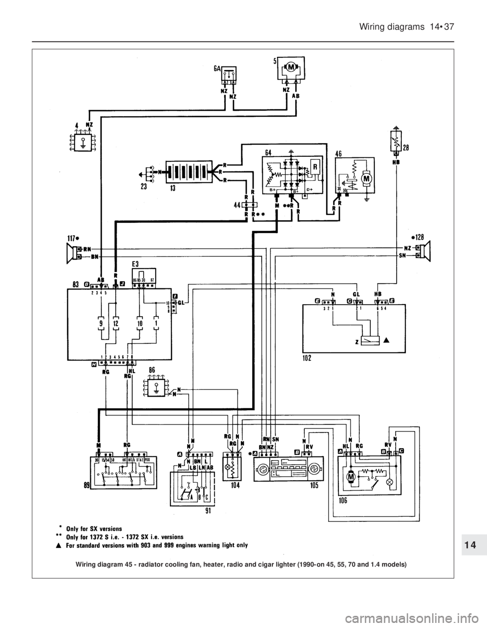
Wiring diagrams 14•37
14
Wiring diagram 45 - radiator cooling fan, heater, radio and cigar lighter (1990-on 45, 55, 70 and 1.4 models)
Page 277 of 303
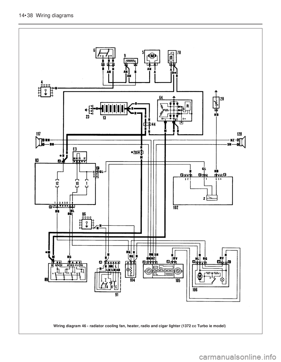
14•38 Wiring diagrams
Wiring diagram 46 - radiator cooling fan, heater, radio and cigar lighter (1372 cc Turbo ie model)
Page 293 of 303

Engine fails to turn when starter
operated
m mFlat battery (recharge use jump leads or
push start)
m mBattery terminals loose or corroded
m mBattery earth to body defective
m mEngine earth strap loose or broken
m mStarter motor (or solenoid) wiring loose or
broken
m mIgnition/starter switch faulty
m mMajor mechanical failure (seizure)
m mStarter or solenoid internal fault (see
Chapter 12)
Starter motor turns engine slowly
m mPartially discharged battery (recharge, use
jump leads, or push start)
m mBattery terminals loose or corroded
m mBattery earth to body defective
m mEngine earth strap loose m mStarter motor (or solenoid) wiring loose
m mStarter motor internal fault (see Chapter 9)
Starter motor spins without
turning engine
m mFlywheel gear teeth damaged or worn
m mStarter motor mounting bolts loose
Engine turns normally but fails to
start
m mDamp or dirty HT leads and distributor cap
(crank engine and check for spark)
m mNo fuel in tank (check for delivery at
carburettor) m mExcessive choke (hot engine) or insufficient
choke (cold engine)
m mFouled or incorrectly gapped spark plugs
(remove, clean and regap)
m mOther ignition system fault (see Chapter 4)
m mOther fuel system fault (see Chapter 3)
m mPoor compression (see Chapter 1)
m mMajor mechanical failure (eg camshaft drive)
Engine fires but will not run
m
mInsufficient choke (cold engine)
m mAir leaks at carburettor or inlet manifold
m mFuel starvation (see Chapter 3)
m mIgnition fault (see Chapter 4)
Engine will not start
REF•10Fault Finding
Spares and tool kit
Most vehicles are supplied only with
sufficient tools for wheel changing; the
Maintenance and minor repairtool kit detailed
in Tools and working facilities,with the
addition of a hammer, is probably sufficient
for those repairs that most motorists would
consider attempting at the roadside. In
addition a few items which can be fitted
without too much trouble in the event of a
breakdown should be carried. Experience and
available space will modify the list below, but
the following may save having to call on
professional assistance:
m mSpark plugs, clean and correctly gapped
m mHT lead and plug cap – long enough to
reach the plug furthest from the distributor
m mDistributor rotor, condenser and contact
breaker points (where applicable)m mDrivebelt(s) — emergency type may
suffice
m mSpare fuses
m mSet of principal light bulbs
m mTin of radiator sealer and hose bandage
m mExhaust bandage
m mRoll of insulating tape
m mLength of soft iron wire
m mLength of electrical flex
m mTorch or inspection lamp (can double as
test lamp)
m mBattery jump leads
m mTow-rope
m mIgnition waterproofing aerosol
m mLitre of engine oil
m mSealed can of hydraulic fluid
m mEmergency windscreen
m mWormdrive clips
m mTube of filler pasteIf spare fuel is carried, a can designed for
the purpose should be used to minimise risks
of leakage and collision damage. A first aid kit
and a warning triangle, whilst not at present
compulsory in the UK, are obviously sensible
items to carry in addition to the above. When
touring abroad it may be advisable to carry
additional spares which, even if you cannot fit
them yourself, could save having to wait while
parts are obtained. The items below may be
worth considering:
m mClutch and throttle cables
m mCylinder head gasket
m mAlternator brushes
m mTyre valve core
One of the motoring organisations will be
able to advise on availability of fuel, etc, in
foreign countries.
A simple test lamp is useful for checking
electrical faultsCarrying a few spares may save you a long walk!
Page 294 of 303

Engine cuts out suddenly –
ignition fault
m mLoose or disconnected LT wires
m mWet HT leads or distributor cap (after
traversing water splash)
m mCoil failure (check for spark)
m mOther ignition fault (see Chapter 4)
Engine misfires before cutting out
– fuel fault
m mFuel tank empty
m mFuel pump defective or filter blocked
(check for delivery)
m mFuel tank filler vent blocked (suction will be
evident on releasing cap)
m mCarburettor needle valve sticking
m mCarburettor jets blocked (fuel contami-
nated)
m mOther fuel system fault (see Chapter 3)
Engine cuts out – other causes
m
mSerious overheating
m mMajor mechanical failure (eg camshaft
drive)
Ignition (no-charge) warning light
illuminated
m mSlack or broken drivebelt — retension or
renew (Chapter 9)
Ignition warning light not
illuminated
m mCoolant loss due to internal or external
leakage (see Chapter 2)
m mThermostat defective
m mLow oil level
m mBrakes binding
m mRadiator clogged externally or internally
m mElectric cooling fan not operating correctly
m mEngine waterways clogged
m mIgnition timing incorrect or automatic
advance malfunctioning
m mMixture too weak
Note: Do not add cold water to an overheated
engine or damage may result
Note: Low oil pressure in a high-mileage
engine at tickover is not necessarily a cause
for concern. Sudden pressure loss at speed is
far more significant. In any event check the
gauge or warning light sender before
condemning the engine.
Gauge reads low or warning light
illuminated with engine running
m mOil level low or incorrect grade
m mDefective gauge or sender unit m mWire to sender unit earthed
m mEngine overheating
m mOil filter clogged or bypass valve defective
m mOil pressure relief valve defective
m mOil pick-up strainer clogged
m mOil pump worn or mountings loose
m mWorn main or big-end bearings
Pre-ignition (pinking) on
acceleration
m mIncorrect grade of fuel
m mIgnition timing incorrect
m mDistributor faulty or worn
m mWorn or maladjusted carburettor
m mExcessive carbon build-up in engine
Whistling or wheezing noises
m
mLeaking vacuum hose
m mLeaking carburettor or manifold gasket
m mBlowing head gasket
Tapping or rattling
m
mIncorrect valve clearances (where appli-
cable)
m mWorn valve gear
m mWorn timing chain or belt
m mBroken piston ring (ticking noise)
Knocking or thumping
m
mUnintentional mechanical contact (eg fan
blades)
m mWorn drivebelt
m mPeripheral component fault (generator,
water pump, etc)
m mWorn big-end bearings (regular heavy
knocking, perhaps less under load)
m mWorn main bearings (rumbling and
knocking, perhaps worsening under load)
m mPiston slap (most noticeable when cold)
Engine noises
Low engine oil pressure
Engine overheatsEngine cuts out and will not restart
Fault FindingREF•11
REF
Crank engine and check for spark. Note
use of insulated tool