1983 FIAT UNO radiator cap
[x] Cancel search: radiator capPage 5 of 303

Safety First!0•5
Working on your car can be dangerous.
This page shows just some of the potential
risks and hazards, with the aim of creating a
safety-conscious attitude.
General hazards
Scalding
• Don’t remove the radiator or expansion
tank cap while the engine is hot.
• Engine oil, automatic transmission fluid or
power steering fluid may also be dangerously
hot if the engine has recently been running.
Burning
• Beware of burns from the exhaust system
and from any part of the engine. Brake discs
and drums can also be extremely hot
immediately after use.
Crushing
• When working under or near
a raised vehicle,
always
supplement the
jack with axle
stands, or use
drive-on
ramps.
Never
venture
under a car which
is only supported by a jack.
• Take care if loosening or tightening high-
torque nuts when the vehicle is on stands.
Initial loosening and final tightening should
be done with the wheels on the ground.
Fire
• Fuel is highly flammable; fuel vapour is
explosive.
• Don’t let fuel spill onto a hot engine.
• Do not smoke or allow naked lights
(including pilot lights) anywhere near a
vehicle being worked on. Also beware of
creating sparks
(electrically or by use of tools).
• Fuel vapour is heavier than air, so don’t
work on the fuel system with the vehicle over
an inspection pit.
• Another cause of fire is an electrical
overload or short-circuit. Take care when
repairing or modifying the vehicle wiring.
• Keep a fire extinguisher handy, of a type
suitable for use on fuel and electrical fires.
Electric shock
• Ignition HT
voltage can be
dangerous,
especially to
people with heart
problems or a
pacemaker. Don’t
work on or near the
ignition system with
the engine running or
the ignition switched on.• Mains voltage is also dangerous. Make
sure that any mains-operated equipment is
correctly earthed. Mains power points should
be protected by a residual current device
(RCD) circuit breaker.
Fume or gas intoxication
• Exhaust fumes are
poisonous; they often
contain carbon
monoxide, which is
rapidly fatal if inhaled.
Never run the
engine in a
confined space
such as a garage
with the doors shut.
• Fuel vapour is also
poisonous, as are the vapours from some
cleaning solvents and paint thinners.
Poisonous or irritant substances
• Avoid skin contact with battery acid and
with any fuel, fluid or lubricant, especially
antifreeze, brake hydraulic fluid and Diesel
fuel. Don’t syphon them by mouth. If such a
substance is swallowed or gets into the eyes,
seek medical advice.
• Prolonged contact with used engine oil can
cause skin cancer. Wear gloves or use a
barrier cream if necessary. Change out of oil-
soaked clothes and do not keep oily rags in
your pocket.
• Air conditioning refrigerant forms a
poisonous gas if exposed to a naked flame
(including a cigarette). It can also cause skin
burns on contact.
Asbestos
• Asbestos dust can cause cancer if inhaled
or swallowed. Asbestos may be found in
gaskets and in brake and clutch linings.
When dealing with such components it is
safest to assume that they contain asbestos.
Special hazards
Hydrofluoric acid
• This extremely corrosive acid is formed
when certain types of synthetic rubber, found
in some O-rings, oil seals, fuel hoses etc, are
exposed to temperatures above 400
0C. The
rubber changes into a charred or sticky
substance containing the acid. Once formed,
the acid remains dangerous for years. If it
gets onto the skin, it may be necessary to
amputate the limb concerned.
• When dealing with a vehicle which has
suffered a fire, or with components salvaged
from such a vehicle, wear protective gloves
and discard them after use.
The battery
• Batteries contain sulphuric acid, which
attacks clothing, eyes and skin. Take care
when topping-up or carrying the battery.
• The hydrogen gas given off by the battery
is highly explosive. Never cause a spark or
allow a naked light nearby. Be careful when
connecting and disconnecting battery
chargers or jump leads.
Air bags
• Air bags can cause injury if they go off
accidentally. Take care when removing the
steering wheel and/or facia. Special storage
instructions may apply.
Diesel injection equipment
• Diesel injection pumps supply fuel at very
high pressure. Take care when working on
the fuel injectors and fuel pipes.
Warning: Never expose the hands,
face or any other part of the body
to injector spray; the fuel can
penetrate the skin with potentially fatal
results.
Remember...
DO
• Do use eye protection when using power
tools, and when working under the vehicle.
• Do wear gloves or use barrier cream to
protect your hands when necessary.
• Do get someone to check periodically
that all is well when working alone on the
vehicle.
• Do keep loose clothing and long hair well
out of the way of moving mechanical parts.
• Do remove rings, wristwatch etc, before
working on the vehicle – especially the
electrical system.
• Do ensure that any lifting or jacking
equipment has a safe working load rating
adequate for the job.
A few tips
DON’T
• Don’t attempt to lift a heavy component
which may be beyond your capability – get
assistance.
• Don’t rush to finish a job, or take
unverified short cuts.
• Don’t use ill-fitting tools which may slip
and cause injury.
• Don’t leave tools or parts lying around
where someone can trip over them. Mop
up oil and fuel spills at once.
• Don’t allow children or pets to play in or
near a vehicle being worked on.
Page 11 of 303
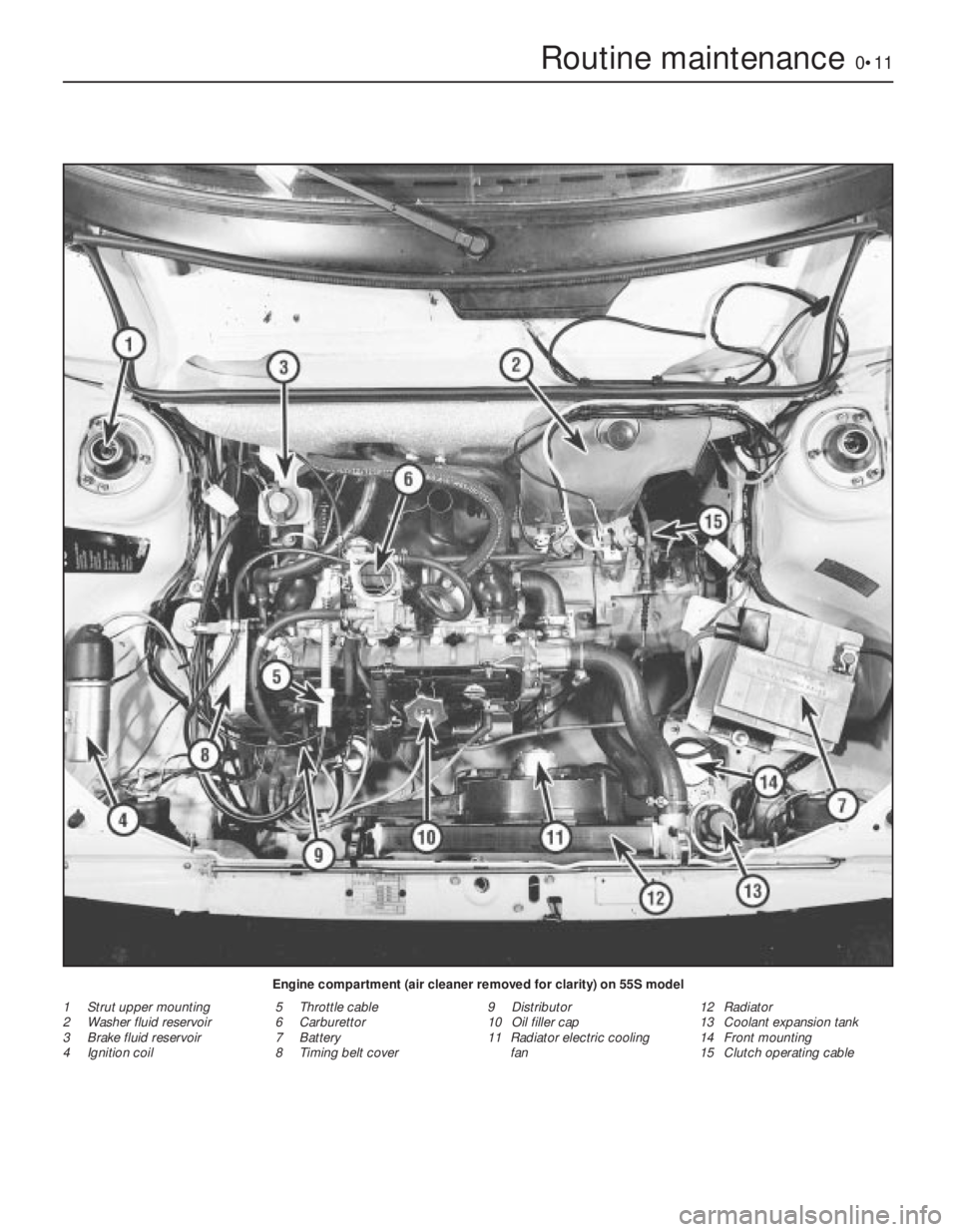
Routine maintenance0•11
Engine compartment (air cleaner removed for clarity) on 55S model
1 Strut upper mounting
2 Washer fluid reservoir
3 Brake fluid reservoir
4 Ignition coil5 Throttle cable
6 Carburettor
7 Battery
8 Timing belt cover9 Distributor
10 Oil filler cap
11 Radiator electric cooling
fan12 Radiator
13 Coolant expansion tank
14 Front mounting
15 Clutch operating cable
Page 51 of 303

2
System type . . . . . . . . . . . . . . . . . . . . . . . . . . . . . . . . . . . . . . . . . . . “No loss” with radiator and integral expansion tank. Electric cooling
fan, belt-driven coolant pump, thermostat on cylinder head
General
Radiator fan cuts in . . . . . . . . . . . . . . . . . . . . . . . . . . . . . . . . . . . . . . . . . 90 to 94ºC (194 to 201ºF)
Radiator fan switches off . . . . . . . . . . . . . . . . . . . . . . . . . . . . . . . . . . . . 85 to 89ºC (185 to 192ºF)
Thermostat opens:
903 cc engine . . . . . . . . . . . . . . . . . . . . . . . . . . . . . . . . . . . . . . . . . . . 85 to 89ºC (185 to 192ºF)
1116 cc and 1301 cc engines . . . . . . . . . . . . . . . . . . . . . . . . . . . . . . . 83 to 87ºC (181 to 188.6ºF)
Fully open:
903 cc . . . . . . . . . . . . . . . . . . . . . . . . . . . . . . . . . . . . . . . . . . . . . . . . . 100ºC (212ºF)
1116 cc and 1301 cc . . . . . . . . . . . . . . . . . . . . . . . . . . . . . . . . . . . . . 95ºC (203ºF)
Expansion tank pressure cap rating . . . . . . . . . . . . . . . . . . . . . . . . . . . . 0.78 bar (11 lbf/in2)
Coolant
Capacity:
903 cc . . . . . . . . . . . . . . . . . . . . . . . . . . . . . . . . . . . . . . . . . . . . . . . . . 4.6 litre (8.1 pint)
1116 cc . . . . . . . . . . . . . . . . . . . . . . . . . . . . . . . . . . . . . . . . . . . . . . . . 6.0 litre (10.6 pint)
1301 cc . . . . . . . . . . . . . . . . . . . . . . . . . . . . . . . . . . . . . . . . . . . . . . . . 6.2 litre (10.9 pint)
Type . . . . . . . . . . . . . . . . . . . . . . . . . . . . . . . . . . . . . . . . . . . . . . . . . . . . Ethylene glycol based antifreeze
Torque wrench settingsNm lbf ft
Temperature sender switch . . . . . . . . . . . . . . . . . . . . . . . . . . . . . . . . . . 49 36
Coolant pump mounting bolts . . . . . . . . . . . . . . . . . . . . . . . . . . . . . . . . 34 25
Alternator adjuster and mountings nuts . . . . . . . . . . . . . . . . . . . . . . . . . 49 36
Chapter 2 Cooling and heating systems
For modifications, and information applicable to later models, see Supplement at end of manual
Coolant mixtures . . . . . . . . . . . . . . . . . . . . . . . . . . . . . . . . . . . . . . . . 3
Coolant pump - removal, overhaul and refitting . . . . . . . . . . . . . . . . 9
Cooling system - draining, flushing and refilling . . . . . . . . . . . . . . . . 2
Cooling system sensors . . . . . . . . . . . . . . . . . . . . . . . . . . . . . . . . . . 10
Description and maintenance . . . . . . . . . . . . . . . . . . . . . . . . . . . . . . 1
Drivebelt - tensioning and renewal . . . . . . . . . . . . . . . . . . . . . . . . . . 8
Fault finding - cooling and heating . . . . . . . . . . . . See end of ChapterHeater - dismantling, overhaul and reassembly . . . . . . . . . . . . . . . . 13
Heater unit - removal and refitting . . . . . . . . . . . . . . . . . . . . . . . . . . 12
Heating and ventilation system - description . . . . . . . . . . . . . . . . . . 11
Radiator - removal and refitting . . . . . . . . . . . . . . . . . . . . . . . . . . . . 7
Radiator fan thermostatic switch - removal, checking and refitting . 5
Radiator fan - removal and refitting . . . . . . . . . . . . . . . . . . . . . . . . . 6
Thermostat - removal, testing and refitting . . . . . . . . . . . . . . . . . . . . 4
2•1
Specifications Contents
1 Description and
maintenance
1
1The cooling system consists of a
front-mounted radiator with built-in expansion
tank, a coolant pump (belt-driven from the
crankshaft pulley) and a thermostatically-
controlled electric cooling fan.
2In order to assist rapid warm-up, athermostat is located in a housing at the
left-hand end of the cylinder head. The hose
connections to the thermostat housing vary
according to model.
3The heater is supplied with coolant from the
engine and incorporates a matrix and blower
with the necessary controls.
4The throttle valve plate block of the
carburettor is coolant-heated as a means of
improving fuel atomisation.
5Maintenance is minimal as in theory no
coolant should ever be lost from theexpansion tank. Regularly check that the
coolant level is between 50.0 and 70.0 mm
(1.97 and 2.8 in) above the MIN mark on the
tank with the engine cold. The need for
regular topping up will indicate a leak
somewhere in the system. If one cannot be
found suspect an internal leak in the engine
although this is usually confirmed by a rise in
the engine oil level and water on the dipstick
(photo). Any topping-up should be done using
an antifreeze mixture (see Section 3), not plain
water.
Easy,suitable for
novice with little
experienceFairly easy,suitable
for beginner with
some experienceFairly difficult,
suitable for competent
DIY mechanic
Difficult,suitable for
experienced DIY
mechanicVery difficult,
suitable for expert DIY
or professional
Degrees of difficulty
54321
Page 52 of 303
6Avoid unscrewing the expansion tank cap
when the engine is hot, but if this must be
done, cover the cap with a cloth to avoid
scalding by escaping steam.
7Periodically, check the condition of all
coolant hoses and tighten the clips.
2 Cooling system- draining,
flushing and refilling
1
1Set the heater temperature lever to
maximum.
2Unscrew the cap from the expansion tank.
3Disconnect the radiator bottom hose and
unscrew the cylinder block drain plug (1116
cc and 1301 cc engines) and allow the coolant
to drain. Refer to photo 29.21B, page 64.
4If the system is in good condition with no
sign of rust or dirt in the drained coolant, then
it may be refilled immediately. If the system
has been neglected and the antifreeze has notbeen regularly renewed and there is evidence
of rust and sediment in the drained liquid then
flush the system through with a cold water
hose.
5If the radiator should appear to be clogged,
it may be necessary to remove it (Section 7)
invert it and reverse flush it using a cold water
hose. If, after a reasonable period the water
still does not run clear, the radiator should be
flushed with a good proprietary cleaning
system. Extensive damage should be repaired
by a specialist or the unit exchanged for a
new or reconditioned radiator.
6Reconnect the bottom hose and screw in
the drain plug.
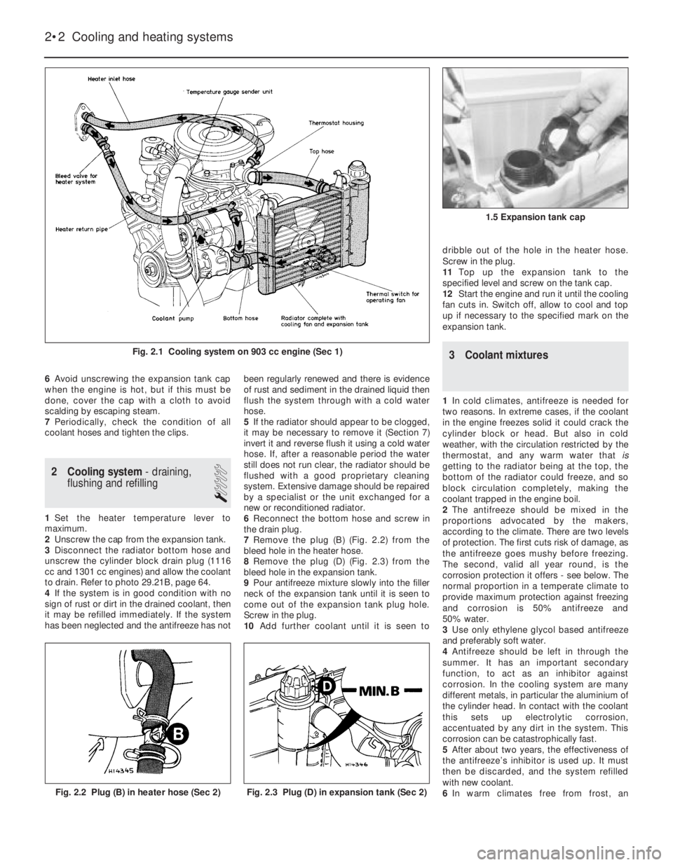
7Remove the plug (B) (Fig. 2.2) from the
bleed hole in the heater hose.
8Remove the plug (D) (Fig. 2.3) from the
bleed hole in the expansion tank.
9Pour antifreeze mixture slowly into the filler
neck of the expansion tank until it is seen to
come out of the expansion tank plug hole.
Screw in the plug.
10Add further coolant until it is seen todribble out of the hole in the heater hose.
Screw in the plug.
11Top up the expansion tank to the
specified level and screw on the tank cap.
12Start the engine and run it until the cooling
fan cuts in. Switch off, allow to cool and top
up if necessary to the specified mark on the
expansion tank.
3 Coolant mixtures
1In cold climates, antifreeze is needed for
two reasons. In extreme cases, if the coolant
in the engine freezes solid it could crack the
cylinder block or head. But also in cold
weather, with the circulation restricted by the
thermostat, and any warm water that is
getting to the radiator being at the top, the
bottom of the radiator could freeze, and so
block circulation completely, making the
coolant trapped in the engine boil.
2The antifreeze should be mixed in the
proportions advocated by the makers,
according to the climate. There are two levels
of protection. The first cuts risk of damage, as
the antifreeze goes mushy before freezing.
The second, valid all year round, is the
corrosion protection it offers - see below. The
normal proportion in a temperate climate to
provide maximum protection against freezing
and corrosion is 50% antifreeze and
50% water.
3Use only ethylene glycol based antifreeze
and preferably soft water.
4Antifreeze should be left in through the
summer. It has an important secondary
function, to act as an inhibitor against
corrosion. In the cooling system are many
different metals, in particular the aluminium of
the cylinder head. In contact with the coolant
this sets up electrolytic corrosion,
accentuated by any dirt in the system. This
corrosion can be catastrophically fast.
5After about two years, the effectiveness of
the antifreeze’s inhibitor is used up. It must
then be discarded, and the system refilled
with new coolant.
6In warm climates free from frost, an
2•2 Cooling and heating systems
Fig. 2.3 Plug (D) in expansion tank (Sec 2)Fig. 2.2 Plug (B) in heater hose (Sec 2)
1.5 Expansion tank cap
Fig. 2.1 Cooling system on 903 cc engine (Sec 1)
Page 58 of 303
Fault finding - cooling and heating systems
2•8 Cooling and heating systems
Overheating
m mInsufficient coolant in system
m mPump ineffective due to slack drivebelt
m mRadiator blocked either internally or externally
m mKinked or collapsed hose causing coolant flow restriction
m mThermostat not working properly
m mEngine out of tune
m mIgnition timing retarded or auto advance malfunction
m mCylinder head gasket blown
m mEngine not yet run-in
m mExhaust system partially blocked
m mEngine oil level too low
m mBrakes binding
Engine running too cool
m
mFaulty, incorrect or missing thermostat
Loss of coolant
m
mLoose hose clips
m mHoses perished or leaking
m mRadiator leaking
m mFiller/pressure cap defective
m mBlown cylinder head gasket
m mCracked cylinder block or head
Heater gives insufficient output
m
mEngine overcooled (see above)
m mHeater matrix blocked
m mHeater controls maladjusted or broken
m mHeater control valve jammed or otherwise
defective
Page 130 of 303
Valve timing clearance:
999 cc . . . . . . . . . . . . . . . . . . . . . . . . . . . . . . . . . . . . . . . . . . . . . . . . . 1.0 mm
1108 cc . . . . . . . . . . . . . . . . . . . . . . . . . . . . . . . . . . . . . . . . . . . . . . . . 0.70 mm
1372 cc . . . . . . . . . . . . . . . . . . . . . . . . . . . . . . . . . . . . . . . . . . . . . . . . 0.80 mm
Valve timing:Inlet Exhaust
999 cc:
Opens . . . . . . . . . . . . . . . . . . . . . . . . . . . . . . . . . . . . . . . . . . . . . . . 1º BTDC 29º BBDC
Closes . . . . . . . . . . . . . . . . . . . . . . . . . . . . . . . . . . . . . . . . . . . . . . . 19º ABDC 9º ATDC
1108 cc:
Opens . . . . . . . . . . . . . . . . . . . . . . . . . . . . . . . . . . . . . . . . . . . . . . . 2º BTDC 42º BBDC
Closes . . . . . . . . . . . . . . . . . . . . . . . . . . . . . . . . . . . . . . . . . . . . . . . 19º ABDC 2º ATDC
1116 cc:
Opens . . . . . . . . . . . . . . . . . . . . . . . . . . . . . . . . . . . . . . . . . . . . . . . 7º BTDC 37º BBDC
Closes . . . . . . . . . . . . . . . . . . . . . . . . . . . . . . . . . . . . . . . . . . . . . . . 35º ABDC 5º ATDC
1299/1301 cc:
Opens . . . . . . . . . . . . . . . . . . . . . . . . . . . . . . . . . . . . . . . . . . . . . . . 9º BTDC 39º BBDC
Closes . . . . . . . . . . . . . . . . . . . . . . . . . . . . . . . . . . . . . . . . . . . . . . . 31º ABDC 1º ATDC
1299/1301 cc Turbo ie:
Opens . . . . . . . . . . . . . . . . . . . . . . . . . . . . . . . . . . . . . . . . . . . . . . . 0º TDC 30º BBDC
Closes . . . . . . . . . . . . . . . . . . . . . . . . . . . . . . . . . . . . . . . . . . . . . . . 40º ABDC 10º ATDC
1372 cc ie:
Opens . . . . . . . . . . . . . . . . . . . . . . . . . . . . . . . . . . . . . . . . . . . . . . . 7º BTDC 37º BBDC
Closes . . . . . . . . . . . . . . . . . . . . . . . . . . . . . . . . . . . . . . . . . . . . . . . 35º ABDC 5º ATDC
1372 cc Turbo ie:
Opens . . . . . . . . . . . . . . . . . . . . . . . . . . . . . . . . . . . . . . . . . . . . . . . 14º BTDC 36º BBDC
Closes . . . . . . . . . . . . . . . . . . . . . . . . . . . . . . . . . . . . . . . . . . . . . . . 44º ABDC 6º ATDC
Cam lift:
999 cc . . . . . . . . . . . . . . . . . . . . . . . . . . . . . . . . . . . . . . . . . . . . . . . . . 7.1 mm
1108 cc . . . . . . . . . . . . . . . . . . . . . . . . . . . . . . . . . . . . . . . . . . . . . . . . 8.0 mm
1116 cc . . . . . . . . . . . . . . . . . . . . . . . . . . . . . . . . . . . . . . . . . . . . . . . . 8.8 mm
1299/1301 cc . . . . . . . . . . . . . . . . . . . . . . . . . . . . . . . . . . . . . . . . . . . 8.0 mm
1372 cc ie . . . . . . . . . . . . . . . . . . . . . . . . . . . . . . . . . . . . . . . . . . . . . . 8.8 mm
1372 cc Turbo ie
Inlet valves . . . . . . . . . . . . . . . . . . . . . . . . . . . . . . . . . . . . . . . . . . . 9.5 mm
Exhaust valves . . . . . . . . . . . . . . . . . . . . . . . . . . . . . . . . . . . . . . . . 8.8 mm
Supplement: Revisions and information on later models 13•5
13
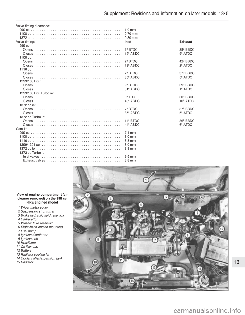
View of engine compartment (air
cleaner removed) on the 999 cc
FIRE engined model
1 Wiper motor cover
2 Suspension strut turret
3 Brake hydraulic fluid reservoir
4 Carburettor
5 Washer fluid reservoir
6 Right-hand engine mounting
7 Fuel pump
8 Ignition distributor
9 Ignition coil
10 Headlamp
11 Oil filler cap
12 Battery
13 Radiator cooling fan
14 Coolant filler/expansion tank
15 Radiator
Page 131 of 303
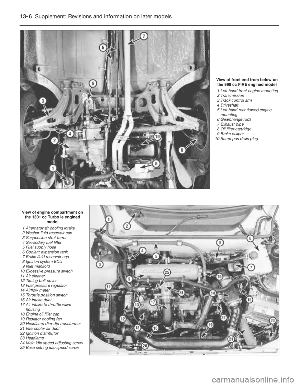
View of front end from below on
the 999 cc FIRE engined model
1 Left hand front engine mounting
2 Transmission
3 Track control arm
4 Driveshaft
5 Left hand rear (lower) engine
mounting
6 Gearchange rods
7 Exhaust pipe
8 Oil filter cartridge
9 Brake caliper
10 Sump pan drain plug
View of engine compartment on
the 1301 cc Turbo ie engined
model
1 Alternator air cooling intake
2 Washer fluid reservoir cap
3 Suspension strut turret
4 Secondary fuel filter
5 Fuel supply hose
6 Coolant expansion tank
7 Brake fluid reservoir cap
8 Ignition system ECU
9 Inlet manifold
10 Excessive pressure switch
11 Air cleaner
12 Timing belt cover
13 Fuel pressure regulator
14 Airflow meter
15 Throttle position switch
16 Air intake duct
17 Air intake to throttle valve
housing
18 Engine oil filler cap
19 Radiator cooling fan
20 Headlamp dim-dip transformer
21 Intercooler air duct
22 Ignition distributor
23 Headlamp
24 Main idle speed adjusting screw
25 Base setting idle speed screw
13•6 Supplement: Revisions and information on later models
Page 132 of 303

Supplement: Revisions and information on later models 13•7
View of engine compartment (air
cleaner removed) on the
1372 cc ie engined model
1 Engine oil level dipstick
2 Timing belt cover
3 Engine mounting (right-hand)
4 Clutch master cylinder fluid
reservoir
5 Fuel supply and return hoses
6 Injection unit
7 Inlet manifold
8 Washer reservoir
9 Brake master cylinder and fluid
reservoir
10 Injection system fuse/relay block
11 Suspension strut turret
12 Ignition coil
13 Ignition system ECU
14 Battery
15 Coolant filter expansion tank
16 Ignition distributor
17 Radiator cooling fan
18 Engine oil filler cap
19 Starter motor
20 Oil filter
View of front end from below on
the 1031 cc Turbo ie engined
model
1 Anti-roll bar
2 Exhaust pipe
3 Track control arm
4 Engine centre mounting
5 Gearchange rods
6 Brake caliper
7 Left-hand driveshaft
8 Intermediate driveshaft
9 Right-hand driveshaft
10 Transmission
11 Engine oil drain plug
12 Auxiliary lamp
13 Horn
14 Intercooler
15 Starter motor
16 Oil filter cartridge
17 Oil pressure sender unit
18 Engine oil cooler
19 Right-hand underwing shield
20 Left-hand underwing shield
13