1983 FIAT UNO radiator
[x] Cancel search: radiatorPage 132 of 303

Supplement: Revisions and information on later models 13•7
View of engine compartment (air
cleaner removed) on the
1372 cc ie engined model
1 Engine oil level dipstick
2 Timing belt cover
3 Engine mounting (right-hand)
4 Clutch master cylinder fluid
reservoir
5 Fuel supply and return hoses
6 Injection unit
7 Inlet manifold
8 Washer reservoir
9 Brake master cylinder and fluid
reservoir
10 Injection system fuse/relay block
11 Suspension strut turret
12 Ignition coil
13 Ignition system ECU
14 Battery
15 Coolant filter expansion tank
16 Ignition distributor
17 Radiator cooling fan
18 Engine oil filler cap
19 Starter motor
20 Oil filter
View of front end from below on
the 1031 cc Turbo ie engined
model
1 Anti-roll bar
2 Exhaust pipe
3 Track control arm
4 Engine centre mounting
5 Gearchange rods
6 Brake caliper
7 Left-hand driveshaft
8 Intermediate driveshaft
9 Right-hand driveshaft
10 Transmission
11 Engine oil drain plug
12 Auxiliary lamp
13 Horn
14 Intercooler
15 Starter motor
16 Oil filter cartridge
17 Oil pressure sender unit
18 Engine oil cooler
19 Right-hand underwing shield
20 Left-hand underwing shield
13
Page 135 of 303
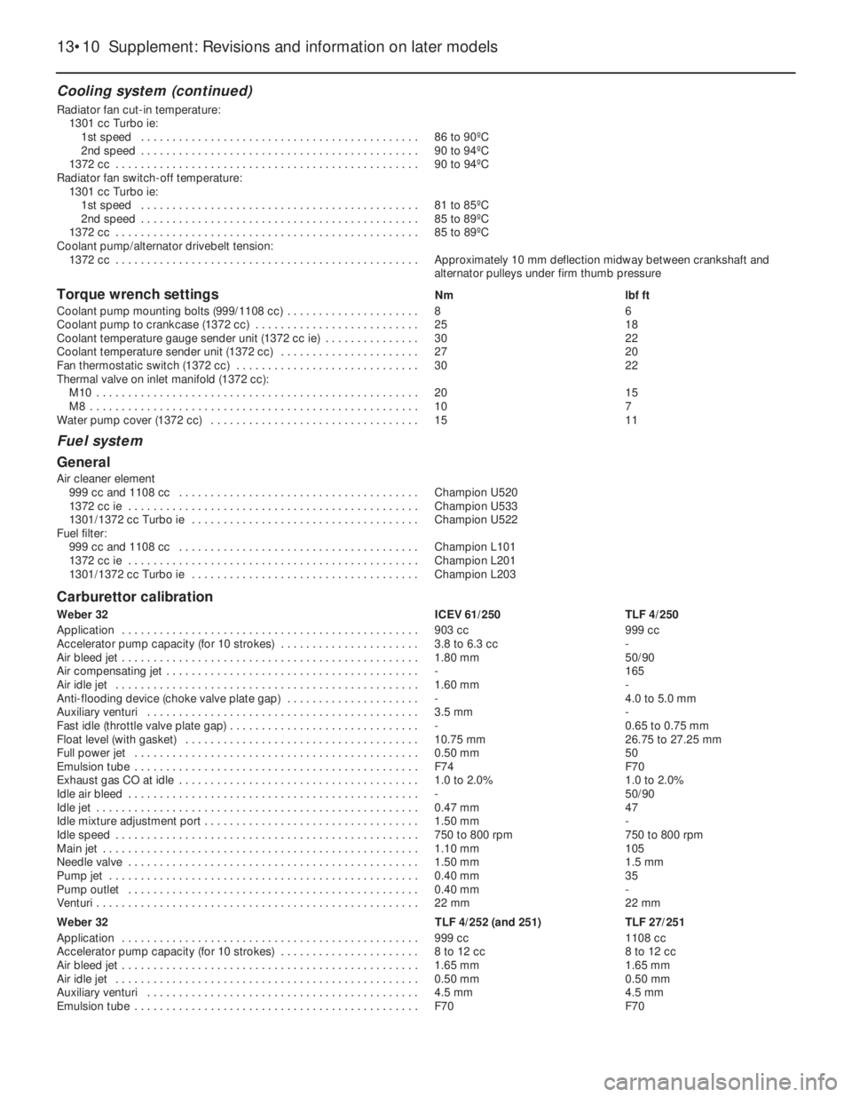
Cooling system (continued)
Radiator fan cut-in temperature:
1301 cc Turbo ie:
1st speed . . . . . . . . . . . . . . . . . . . . . . . . . . . . . . . . . . . . . . . . . . . . 86 to 90ºC
2nd speed . . . . . . . . . . . . . . . . . . . . . . . . . . . . . . . . . . . . . . . . . . . . 90 to 94ºC
1372 cc . . . . . . . . . . . . . . . . . . . . . . . . . . . . . . . . . . . . . . . . . . . . . . . . 90 to 94ºC
Radiator fan switch-off temperature:
1301 cc Turbo ie:
1st speed . . . . . . . . . . . . . . . . . . . . . . . . . . . . . . . . . . . . . . . . . . . . 81 to 85ºC
2nd speed . . . . . . . . . . . . . . . . . . . . . . . . . . . . . . . . . . . . . . . . . . . . 85 to 89ºC
1372 cc . . . . . . . . . . . . . . . . . . . . . . . . . . . . . . . . . . . . . . . . . . . . . . . . 85 to 89ºC
Coolant pump/alternator drivebelt tension:
1372 cc . . . . . . . . . . . . . . . . . . . . . . . . . . . . . . . . . . . . . . . . . . . . . . . . Approximately 10 mm deflection midway between crankshaft and
alternator pulleys under firm thumb pressure
Torque wrench settingsNm lbf ft
Coolant pump mounting bolts (999/1108 cc) . . . . . . . . . . . . . . . . . . . . . 8 6
Coolant pump to crankcase (1372 cc) . . . . . . . . . . . . . . . . . . . . . . . . . . 25 18
Coolant temperature gauge sender unit (1372 cc ie) . . . . . . . . . . . . . . . 30 22
Coolant temperature sender unit (1372 cc) . . . . . . . . . . . . . . . . . . . . . . 27 20
Fan thermostatic switch (1372 cc) . . . . . . . . . . . . . . . . . . . . . . . . . . . . . 30 22
Thermal valve on inlet manifold (1372 cc):
M10 . . . . . . . . . . . . . . . . . . . . . . . . . . . . . . . . . . . . . . . . . . . . . . . . . . . 20 15
M8 . . . . . . . . . . . . . . . . . . . . . . . . . . . . . . . . . . . . . . . . . . . . . . . . . . . . 10 7
Water pump cover (1372 cc) . . . . . . . . . . . . . . . . . . . . . . . . . . . . . . . . . 15 11
Fuel system
General
Air cleaner element
999 cc and 1108 cc . . . . . . . . . . . . . . . . . . . . . . . . . . . . . . . . . . . . . . Champion U520
1372 cc ie . . . . . . . . . . . . . . . . . . . . . . . . . . . . . . . . . . . . . . . . . . . . . . Champion U533
1301/1372 cc Turbo ie . . . . . . . . . . . . . . . . . . . . . . . . . . . . . . . . . . . . Champion U522
Fuel filter:
999 cc and 1108 cc . . . . . . . . . . . . . . . . . . . . . . . . . . . . . . . . . . . . . . Champion L101
1372 cc ie . . . . . . . . . . . . . . . . . . . . . . . . . . . . . . . . . . . . . . . . . . . . . . Champion L201
1301/1372 cc Turbo ie . . . . . . . . . . . . . . . . . . . . . . . . . . . . . . . . . . . . Champion L203
Carburettor calibration
Weber 32 ICEV 61/250 TLF 4/250
Application . . . . . . . . . . . . . . . . . . . . . . . . . . . . . . . . . . . . . . . . . . . . . . . 903 cc 999 cc
Accelerator pump capacity (for 10 strokes) . . . . . . . . . . . . . . . . . . . . . . 3.8 to 6.3 cc -
Air bleed jet . . . . . . . . . . . . . . . . . . . . . . . . . . . . . . . . . . . . . . . . . . . . . . . 1.80 mm 50/90
Air compensating jet . . . . . . . . . . . . . . . . . . . . . . . . . . . . . . . . . . . . . . . . - 165
Air idle jet . . . . . . . . . . . . . . . . . . . . . . . . . . . . . . . . . . . . . . . . . . . . . . . . 1.60 mm -
Anti-flooding device (choke valve plate gap) . . . . . . . . . . . . . . . . . . . . . - 4.0 to 5.0 mm
Auxiliary venturi . . . . . . . . . . . . . . . . . . . . . . . . . . . . . . . . . . . . . . . . . . . 3.5 mm -
Fast idle (throttle valve plate gap) . . . . . . . . . . . . . . . . . . . . . . . . . . . . . . - 0.65 to 0.75 mm
Float level (with gasket) . . . . . . . . . . . . . . . . . . . . . . . . . . . . . . . . . . . . . 10.75 mm 26.75 to 27.25 mm
Full power jet . . . . . . . . . . . . . . . . . . . . . . . . . . . . . . . . . . . . . . . . . . . . . 0.50 mm 50
Emulsion tube . . . . . . . . . . . . . . . . . . . . . . . . . . . . . . . . . . . . . . . . . . . . . F74 F70
Exhaust gas CO at idle . . . . . . . . . . . . . . . . . . . . . . . . . . . . . . . . . . . . . . 1.0 to 2.0% 1.0 to 2.0%
Idle air bleed . . . . . . . . . . . . . . . . . . . . . . . . . . . . . . . . . . . . . . . . . . . . . . - 50/90
Idle jet . . . . . . . . . . . . . . . . . . . . . . . . . . . . . . . . . . . . . . . . . . . . . . . . . . . 0.47 mm 47
Idle mixture adjustment port . . . . . . . . . . . . . . . . . . . . . . . . . . . . . . . . . . 1.50 mm -
Idle speed . . . . . . . . . . . . . . . . . . . . . . . . . . . . . . . . . . . . . . . . . . . . . . . . 750 to 800 rpm 750 to 800 rpm
Main jet . . . . . . . . . . . . . . . . . . . . . . . . . . . . . . . . . . . . . . . . . . . . . . . . . . 1.10 mm 105
Needle valve . . . . . . . . . . . . . . . . . . . . . . . . . . . . . . . . . . . . . . . . . . . . . . 1.50 mm 1.5 mm
Pump jet . . . . . . . . . . . . . . . . . . . . . . . . . . . . . . . . . . . . . . . . . . . . . . . . . 0.40 mm 35
Pump outlet . . . . . . . . . . . . . . . . . . . . . . . . . . . . . . . . . . . . . . . . . . . . . . 0.40 mm -
Venturi . . . . . . . . . . . . . . . . . . . . . . . . . . . . . . . . . . . . . . . . . . . . . . . . . . . 22 mm 22 mm
Weber 32 TLF 4/252 (and 251) TLF 27/251
Application . . . . . . . . . . . . . . . . . . . . . . . . . . . . . . . . . . . . . . . . . . . . . . . 999 cc 1108 cc
Accelerator pump capacity (for 10 strokes) . . . . . . . . . . . . . . . . . . . . . . 8 to 12 cc 8 to 12 cc
Air bleed jet . . . . . . . . . . . . . . . . . . . . . . . . . . . . . . . . . . . . . . . . . . . . . . . 1.65 mm 1.65 mm
Air idle jet . . . . . . . . . . . . . . . . . . . . . . . . . . . . . . . . . . . . . . . . . . . . . . . . 0.50 mm 0.50 mm
Auxiliary venturi . . . . . . . . . . . . . . . . . . . . . . . . . . . . . . . . . . . . . . . . . . . 4.5 mm 4.5 mm
Emulsion tube . . . . . . . . . . . . . . . . . . . . . . . . . . . . . . . . . . . . . . . . . . . . . F70 F70
13•10 Supplement: Revisions and information on later models
Page 140 of 303

Torque wrench settingsNm lbf ft
Driveshaft flange connecting bolts (Turbo ie) . . . . . . . . . . . . . . . . . . . . . 43 32
Final drive output shaft bearing cover bolts (Turbo ie) . . . . . . . . . . . . . . 24 18
Intermediate shaft support to crankcase (Turbo ie) . . . . . . . . . . . . . . . . 48 35
Braking system (903, 999, 1108, 1116 and 1372 cc)
General
Note:The following items differ, or are additional to those specified in Chapter 8:
Master cylinder bore diameter:
903 cc, 999 cc, 1108 cc and 1116 cc . . . . . . . . . . . . . . . . . . . . . . . . . 19.05 mm
1372 cc ie . . . . . . . . . . . . . . . . . . . . . . . . . . . . . . . . . . . . . . . . . . . . . . 20.65 mm
Vacuum servo diameter . . . . . . . . . . . . . . . . . . . . . . . . . . . . . . . . . . . . . 152.4 mm
Hydraulic push rod-to-master cylinder support plate clearance . . . . . . 0.825 to 1.025 mm
Braking system (1301 and 1372 cc Turbo ie)
General
System type . . . . . . . . . . . . . . . . . . . . . . . . . . . . . . . . . . . . . . . . . . . . . . Four-wheel discs, ventilated front, solid rear. Vacuum servo. Pressure
regulating valve on rear brakes
Master cylinder bore diameter . . . . . . . . . . . . . . . . . . . . . . . . . . . . . . . . 22.225 mm
Vacuum servo diameter . . . . . . . . . . . . . . . . . . . . . . . . . . . . . . . . . . . . . 177.8 mm
Front disc brakes
Disc diameter . . . . . . . . . . . . . . . . . . . . . . . . . . . . . . . . . . . . . . . . . . . . . 240.0 mm
Disc thickness - new . . . . . . . . . . . . . . . . . . . . . . . . . . . . . . . . . . . . . . . 19.9 to 20.1 mm
Disc thickness - minimum (refinishing) . . . . . . . . . . . . . . . . . . . . . . . . . . 18.6 mm
Disc thickness - minimum (wear limit) . . . . . . . . . . . . . . . . . . . . . . . . . . 18.2 mm
Minimum thickness of pad friction material . . . . . . . . . . . . . . . . . . . . . . 1.5 mm
Caliper cylinder diameter . . . . . . . . . . . . . . . . . . . . . . . . . . . . . . . . . . . . 48.0 mm
Rear disc brakes
Disc diameter . . . . . . . . . . . . . . . . . . . . . . . . . . . . . . . . . . . . . . . . . . . . . 227.0 mm
Disc thickness - new . . . . . . . . . . . . . . . . . . . . . . . . . . . . . . . . . . . . . . . 10.7 to 10.9 mm
Disc thickness minimum (refinishing):
1301 cc Turbo ie . . . . . . . . . . . . . . . . . . . . . . . . . . . . . . . . . . . . . . . . . 9.7 mm
1372 cc Turbo ie . . . . . . . . . . . . . . . . . . . . . . . . . . . . . . . . . . . . . . . . . 9.35 mm
Disc thickness - minimum (wear limit) . . . . . . . . . . . . . . . . . . . . . . . . . . 9.0 mm
Minimum thickness of pad friction material . . . . . . . . . . . . . . . . . . . . . . 1.5 mm
Caliper cylinder diameter . . . . . . . . . . . . . . . . . . . . . . . . . . . . . . . . . . . . 34.0 mm
Torque wrench settingsNm lbf ft
Front caliper cylinder housing mounting bolts . . . . . . . . . . . . . . . . . . . . 52 38
Front caliper support bracket bolts . . . . . . . . . . . . . . . . . . . . . . . . . . . . 52 38
Front disc fixing bolts . . . . . . . . . . . . . . . . . . . . . . . . . . . . . . . . . . . . . . . 25 18
Rear caliper support bracket bolts . . . . . . . . . . . . . . . . . . . . . . . . . . . . . 25 18
Rear caliper cylinder housing mounting bolts . . . . . . . . . . . . . . . . . . . . 52 38
Electrical system
Battery
Turbo ie engine models . . . . . . . . . . . . . . . . . . . . . . . . . . . . . . . . . . . . . 45 Ah
Fuses (903, 999, 1116, 1299/1301 and 1301 cc Turbo ie)
Fuse No. Rating Circuit
1 7.5 . . . . . . . . . . . . . . . . . . . . . . . . . . . . . . . . . . . . . . . . . . . . LH tail, RH front parking, rear number plate, check panel
2 7.5 . . . . . . . . . . . . . . . . . . . . . . . . . . . . . . . . . . . . . . . . . . . . RH tail, LH front parking, cigar lighting, clock light, heater control
illumination, map reading lamp.
3 10 . . . . . . . . . . . . . . . . . . . . . . . . . . . . . . . . . . . . . . . . . . . . . RH headlamp main beam
4 10 . . . . . . . . . . . . . . . . . . . . . . . . . . . . . . . . . . . . . . . . . . . . . LH headlamp main beam and warning light
5 25 . . . . . . . . . . . . . . . . . . . . . . . . . . . . . . . . . . . . . . . . . . . . . Radiator cooling fan, econometer and horns
6 10 . . . . . . . . . . . . . . . . . . . . . . . . . . . . . . . . . . . . . . . . . . . . . Cigar lighter, courtesy lamps, digital clock, stop-lamp switch, clock
and radio
7 10 . . . . . . . . . . . . . . . . . . . . . . . . . . . . . . . . . . . . . . . . . . . . . RH headlamp dipped beam
8 10 . . . . . . . . . . . . . . . . . . . . . . . . . . . . . . . . . . . . . . . . . . . . . LH headlamp dipped beam, rear fog warning lamp and indicator
9 20 . . . . . . . . . . . . . . . . . . . . . . . . . . . . . . . . . . . . . . . . . . . . . Heated rear screen and warning lamp
10 10 . . . . . . . . . . . . . . . . . . . . . . . . . . . . . . . . . . . . . . . . . . . . . Instrument panel, stop-lamps, direction indicators, reversing lamps
and warning module
11 20 . . . . . . . . . . . . . . . . . . . . . . . . . . . . . . . . . . . . . . . . . . . . . Heater fan, fan control illumination and digital clock
12 20 . . . . . . . . . . . . . . . . . . . . . . . . . . . . . . . . . . . . . . . . . . . . . Windscreen wiper, washer pump and rear screen wiper
13 - . . . . . . . . . . . . . . . . . . . . . . . . . . . . . . . . . . . . . . . . . . . . . . Spare
14 10 . . . . . . . . . . . . . . . . . . . . . . . . . . . . . . . . . . . . . . . . . . . . . Hazard warning lamps and indicator
Supplement: Revisions and information on later models 13•15
13
Page 141 of 303

Fuses (903, 999, 1116, 1299/1301 and 1301 cc Turbo ie) (continued)
Fuse No. Rating Circuit
Supplementary fuses at side of main fuse block:
A 20 . . . . . . . . . . . . . . . . . . . . . . . . . . . . . . . . . . . . . . . . . . . . . Front fog lamps
B 30 . . . . . . . . . . . . . . . . . . . . . . . . . . . . . . . . . . . . . . . . . . . . . Cooling fan (Turbo ie models)
C 10 . . . . . . . . . . . . . . . . . . . . . . . . . . . . . . . . . . . . . . . . . . . . . Fuel injector cooling fan (Turbo ie models)
D 30 . . . . . . . . . . . . . . . . . . . . . . . . . . . . . . . . . . . . . . . . . . . . . Electric windows
E 10 . . . . . . . . . . . . . . . . . . . . . . . . . . . . . . . . . . . . . . . . . . . . . Fuel pump (Turbo ie models)
Fuses (later 903, 999, 1108, 1372 ie and 1372 cc Turbo ie)
Fuse Rating Circuit
1 7.5 . . . . . . . . . . . . . . . . . . . . . . . . . . . . . . . . . . . . . . . . . . . . LH tail, RH front parking, rear number plate lamps and check panel
2 7.5 . . . . . . . . . . . . . . . . . . . . . . . . . . . . . . . . . . . . . . . . . . . . RH tail, LH front parking, cigar lighter illumination, clock light, heater
control illumination and map reading light
3 10 . . . . . . . . . . . . . . . . . . . . . . . . . . . . . . . . . . . . . . . . . . . . . RH headlamp main beam
4 10 . . . . . . . . . . . . . . . . . . . . . . . . . . . . . . . . . . . . . . . . . . . . . LH headlamp main beam and warning light
5 25 . . . . . . . . . . . . . . . . . . . . . . . . . . . . . . . . . . . . . . . . . . . . . Radiator cooling fan (except Turbo ie models) and horn
6 10 . . . . . . . . . . . . . . . . . . . . . . . . . . . . . . . . . . . . . . . . . . . . . Cigar lighter, courtesy lamps, digital clock, stop-lamp switch, clock
and radio
7 10 . . . . . . . . . . . . . . . . . . . . . . . . . . . . . . . . . . . . . . . . . . . . . RH headlamp dipped beam
8 10 . . . . . . . . . . . . . . . . . . . . . . . . . . . . . . . . . . . . . . . . . . . . . LH headlamp dipped beam
9 10 . . . . . . . . . . . . . . . . . . . . . . . . . . . . . . . . . . . . . . . . . . . . . Rear fog lamp and warning lamp
10 20 . . . . . . . . . . . . . . . . . . . . . . . . . . . . . . . . . . . . . . . . . . . . . Heated rear screen and warning lamp
11 10 . . . . . . . . . . . . . . . . . . . . . . . . . . . . . . . . . . . . . . . . . . . . . Instrument panel, stop-lamps, direction indicators, reversing lamps,
warning module and carburettor cut-off (FIRE models only)
12 20 . . . . . . . . . . . . . . . . . . . . . . . . . . . . . . . . . . . . . . . . . . . . . Heater fan, heater/ventilation control illumination lights and digital
clock light
13 20 . . . . . . . . . . . . . . . . . . . . . . . . . . . . . . . . . . . . . . . . . . . . . Windscreen wiper, windscreen washer pump and rear wiper/washer
(where fitted)
14 20 . . . . . . . . . . . . . . . . . . . . . . . . . . . . . . . . . . . . . . . . . . . . . Horns and relay
15 10 . . . . . . . . . . . . . . . . . . . . . . . . . . . . . . . . . . . . . . . . . . . . . Hazard warning light and indicator light
Supplementary fuses at side of main fuse block:
A 30 . . . . . . . . . . . . . . . . . . . . . . . . . . . . . . . . . . . . . . . . . . . . . Electric windows
B 25 . . . . . . . . . . . . . . . . . . . . . . . . . . . . . . . . . . . . . . . . . . . . . Central locking (where fitted)
C 10 . . . . . . . . . . . . . . . . . . . . . . . . . . . . . . . . . . . . . . . . . . . . . Injector cooling fan (where fitted)
D 20 . . . . . . . . . . . . . . . . . . . . . . . . . . . . . . . . . . . . . . . . . . . . . Headlamp washers (where fitted)
E 20 . . . . . . . . . . . . . . . . . . . . . . . . . . . . . . . . . . . . . . . . . . . . . Foglamp and warning lamp
F - . . . . . . . . . . . . . . . . . . . . . . . . . . . . . . . . . . . . . . . . . . . . . . Spare
G 10 . . . . . . . . . . . . . . . . . . . . . . . . . . . . . . . . . . . . . . . . . . . . . Fuel pump (fuel injection models)
-10 . . . . . . . . . . . . . . . . . . . . . . . . . . . . . . . . . . . . . . . . . . . . . Heated Lambda sensor
Supplementary fuses on steering column relay bracket:
-10 . . . . . . . . . . . . . . . . . . . . . . . . . . . . . . . . . . . . . . . . . . . . . Antiskid monitor circuit (where fitted)
-25 . . . . . . . . . . . . . . . . . . . . . . . . . . . . . . . . . . . . . . . . . . . . . Antiskid supply circuit (where fitted)
Steering and suspension
General
1301 cc Turbo ie
Castor . . . . . . . . . . . . . . . . . . . . . . . . . . . . . . . . . . . . . . . . . . . . . . . . . . . 1º 55’ to 2º 35’ positive
Number of turns of steering wheel, lock-to-lock . . . . . . . . . . . . . . . . . . 3.42
Later models
Steering angles:
Camber . . . . . . . . . . . . . . . . . . . . . . . . . . . . . . . . . . . . . . . . . . . . . . . . -30’ ± 30’
Castor . . . . . . . . . . . . . . . . . . . . . . . . . . . . . . . . . . . . . . . . . . . . . . . . . 2º10’ ± 15’
Toe-in . . . . . . . . . . . . . . . . . . . . . . . . . . . . . . . . . . . . . . . . . . . . . . . . . 0 to 2.0 mm
1301/1372 cc Turbo ie
Steering angles of roadwheels:
Inner wheel . . . . . . . . . . . . . . . . . . . . . . . . . . . . . . . . . . . . . . . . . . . . . 36º 43’
Outer wheel . . . . . . . . . . . . . . . . . . . . . . . . . . . . . . . . . . . . . . . . . . . . . 31º 27’
Torque wrench settingsNm lbf ft
Anti-roll bar clamp bolts (1301 and 1372 cc Turbo ie) . . . . . . . . . . . . . . 25 18
Anti-roll bar end fixing nuts (1301 and 1372 cc Turbo ie) . . . . . . . . . . . 15 11
13•16 Supplement: Revisions and information on later models
Page 151 of 303
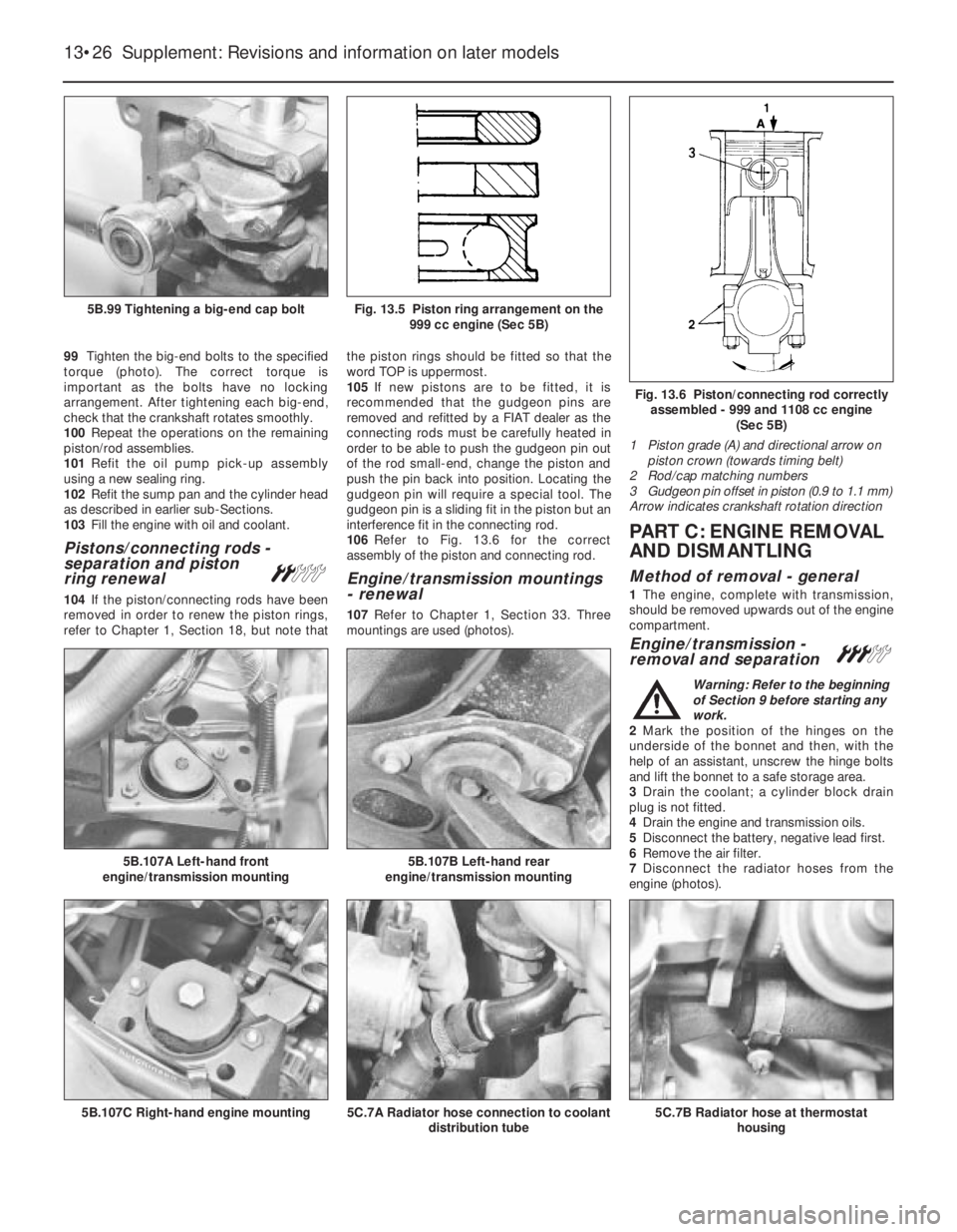
99Tighten the big-end bolts to the specified
torque (photo). The correct torque is
important as the bolts have no locking
arrangement. After tightening each big-end,
check that the crankshaft rotates smoothly.
100Repeat the operations on the remaining
piston/rod assemblies.
101Refit the oil pump pick-up assembly
using a new sealing ring.
102Refit the sump pan and the cylinder head
as described in earlier sub-Sections.
103Fill the engine with oil and coolant.
Pistons/connecting rods -
separation and piston
ring renewal
ª
104If the piston/connecting rods have been
removed in order to renew the piston rings,
refer to Chapter 1, Section 18, but note thatthe piston rings should be fitted so that the
word TOP is uppermost.
105If new pistons are to be fitted, it is
recommended that the gudgeon pins are
removed and refitted by a FIAT dealer as the
connecting rods must be carefully heated in
order to be able to push the gudgeon pin out
of the rod small-end, change the piston and
push the pin back into position. Locating the
gudgeon pin will require a special tool. The
gudgeon pin is a sliding fit in the piston but an
interference fit in the connecting rod.
106Refer to Fig. 13.6 for the correct
assembly of the piston and connecting rod.
Engine/transmission mountings
- renewal
107Refer to Chapter 1, Section 33. Three
mountings are used (photos).
PART C: ENGINE REMOVAL
AND DISMANTLING
Method of removal - general
1The engine, complete with transmission,
should be removed upwards out of the engine
compartment.
Engine/transmission -
removal and separation #
Warning: Refer to the beginning
of Section 9 before starting any
work.
2Mark the position of the hinges on the
underside of the bonnet and then, with the
help of an assistant, unscrew the hinge bolts
and lift the bonnet to a safe storage area.
3Drain the coolant; a cylinder block drain
plug is not fitted.
4Drain the engine and transmission oils.
5Disconnect the battery, negative lead first.
6Remove the air filter.
7Disconnect the radiator hoses from the
engine (photos).
13•26 Supplement: Revisions and information on later models
5C.7B Radiator hose at thermostat
housing5C.7A Radiator hose connection to coolant
distribution tube5B.107C Right-hand engine mounting
5B.107B Left-hand rear
engine/transmission mounting5B.107A Left-hand front
engine/transmission mounting
Fig. 13.6 Piston/connecting rod correctly
assembled - 999 and 1108 cc engine
(Sec 5B)
1 Piston grade (A) and directional arrow on
piston crown (towards timing belt)
2 Rod/cap matching numbers
3 Gudgeon pin offset in piston (0.9 to 1.1 mm)
Arrow indicates crankshaft rotation direction
Fig. 13.5 Piston ring arrangement on the
999 cc engine (Sec 5B)5B.99 Tightening a big-end cap bolt
Page 152 of 303
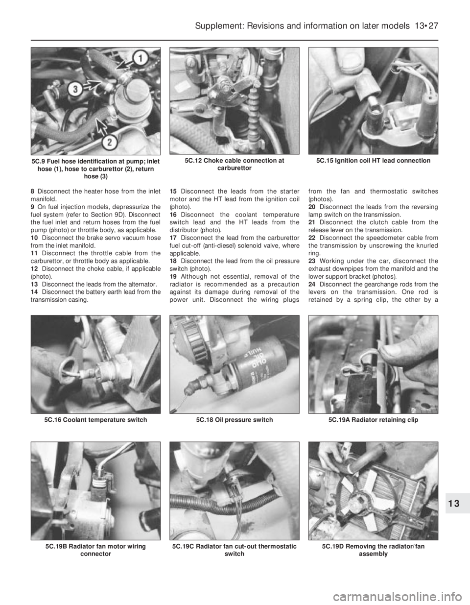
8Disconnect the heater hose from the inlet
manifold.
9On fuel injection models, depressurize the
fuel system (refer to Section 9D). Disconnect
the fuel inlet and return hoses from the fuel
pump (photo) or throttle body, as applicable.
10Disconnect the brake servo vacuum hose
from the inlet manifold.
11Disconnect the throttle cable from the
carburettor, or throttle body as applicable.
12Disconnect the choke cable, if applicable
(photo).
13Disconnect the leads from the alternator.
14Disconnect the battery earth lead from the
transmission casing.15Disconnect the leads from the starter
motor and the HT lead from the ignition coil
(photo).
16Disconnect the coolant temperature
switch lead and the HT leads from the
distributor (photo).
17Disconnect the lead from the carburettor
fuel cut-off (anti-diesel) solenoid valve, where
applicable.
18Disconnect the lead from the oil pressure
switch (photo).
19Although not essential, removal of the
radiator is recommended as a precaution
against its damage during removal of the
power unit. Disconnect the wiring plugs from the fan and thermostatic switches
(photos).
20Disconnect the leads from the reversing
lamp switch on the transmission.
21Disconnect the clutch cable from the
release lever on the transmission.
22Disconnect the speedometer cable from
the transmission by unscrewing the knurled
ring.
23Working under the car, disconnect the
exhaust downpipes from the manifold and the
lower support bracket (photos).
24Disconnect the gearchange rods from the
levers on the transmission. One rod is
retained by a spring clip, the other by a
Supplement: Revisions and information on later models 13•27
5C.15 Ignition coil HT lead connection5C.12 Choke cable connection at
carburettor5C.9 Fuel hose identification at pump; inlet
hose (1), hose to carburettor (2), return
hose (3)
5C.19D Removing the radiator/fan
assembly5C.19C Radiator fan cut-out thermostatic
switch5C.19B Radiator fan motor wiring
connector
5C.19A Radiator retaining clip5C.18 Oil pressure switch5C.16 Coolant temperature switch
13
Page 180 of 303

Coolant pump -
removal and refitting#
11The coolant pump is located on the
crankshaft pulley end of the engine and is
driven by the timing belt.
12The pump cannot be repaired and must
be regarded as disposable.
13Drain the cooling system.
14Remove the timing belt cover and then set
No. 1 piston to TDC. To achieve this, turn the
crankshaft pulley bolt until the camshaft
sprocket timing mark is aligned with the one
on the cylinder head.
15Release the belt tensioner and slip the
timing belt off the camshaft and coolant pump
sprockets.
16Unbolt and remove the coolant pump and
clean the mounting face of all old gasket
material.
17Apply a continuous bead of RTV silicone
sealant (instant gasket) to the mounting face
of the coolant pump and bolt it into position
(photos).
18Check that the camshaft sprocket and the
crankshaft have not been moved and fit the
timing belt to the camshaft and coolant pump
sprockets. The pump sprocket does not
require setting in any particular position
before connecting the timing belt.
19Tension the belt as described in Sec-
tion 5B of this Chapter.
20Fit the timing belt cover.
21After allowing one hour for the gasket
material to cure, refill and bleed the cooling
system.
PART B:
1301 CC TURBO IE ENGINE
Description
1The cooling system on this model has flow
and return connections to the turbocharger,
and is an essential means of cooling the
turbocharger.
2The radiator cooling fan is of two-speed
type, being controlled by a two-stage
thermostatic switch screwed into the radiator
side tank.
3According to the coolant temperature level,
the fan speed is regulated to provide the most
effective cooling.
4The remote cooling system expansion tank
is mounted in the left-hand rear corner of the
engine compartment (photo).
PART C:
1372 CC IE AND 1372 CC
TURBO IE ENGINES
Description
1The cooling system layout and components
for the 1372 cc engines is shown in
Figs. 13.29 and 13.30.
2The system on each engine operates in
essentially the same manner as that
described for the other models in Chapter 2,
but the location of components and the
coolant hose routings differ according to
model. The cooling system expansion tank
location differs according to model, being
either located on the side of the radiator ormounted separately on the side of the inner
wing panel.
3On Turbo models, the cooling system also
assists in cooling the turbocharger.
Maintenance
4The maintenance procedures are
essentially the same as those described for
the other models in Chapter 2.
Cooling system - draining,
flushing and refillingÁ
Warning: Wait until the engine is
cold before starting this
procedure. Do not allow
antifreeze to come into contact
with your skin or painted surfaces of the
vehicle. Rinse off spills immediately with
plenty of water. Never leave antifreeze
lying around in an open container or in a
puddle in the driveway or on the garage
floor. Children and pets are attracted by its
sweet smell. Antifreeze is fatal if ingested.
5Disconnect the battery negative lead.
6Working inside the vehicle, turn the heater
temperature control knob fully to the right,
which will fully open the heater coolant valve.
7With the expansion tank cap removed,
place a suitable container beneath the
radiator bottom hose.
8Loosen the clip and ease the bottom hose
away from the radiator outlet (photo). Allow
the coolant to drain into the container.
9Reposition the container under the front of
the cylinder block, and unscrew the cylinder
block drain plug (photo). Allow the coolant to
drain into the container.
Supplement: Revisions and information on later models 13•55
8A.17B Tightening the coolant pump bolts8A.17A Fitting the coolant pump to the
999 cc engineFig. 13.28 Sectional view of the coolant
pump on the 999 and 1108 cc engines
(Sec 8A)
8C.9 Cylinder block drain plug8C.8 Bottom hose connection to the
radiator8B.4 Topping up the expansion tank with
antifreeze on the 1301 cc engine
13
Page 181 of 303
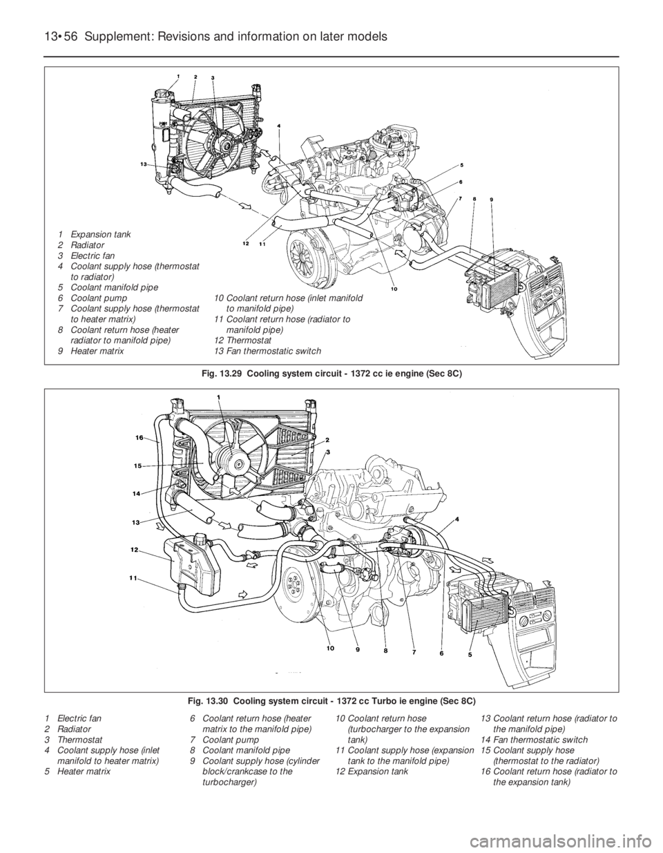
1 Electric fan
2 Radiator
3 Thermostat
4 Coolant supply hose (inlet
manifold to heater matrix)
5 Heater matrix6 Coolant return hose (heater
matrix to the manifold pipe)
7 Coolant pump
8 Coolant manifold pipe
9 Coolant supply hose (cylinder
block/crankcase to the
turbocharger)10 Coolant return hose
(turbocharger to the expansion
tank)
11 Coolant supply hose (expansion
tank to the manifold pipe)
12 Expansion tank13 Coolant return hose (radiator to
the manifold pipe)
14 Fan thermostatic switch
15 Coolant supply hose
(thermostat to the radiator)
16 Coolant return hose (radiator to
the expansion tank)
13•56 Supplement: Revisions and information on later models
Fig. 13.29 Cooling system circuit - 1372 cc ie engine (Sec 8C)
Fig. 13.30 Cooling system circuit - 1372 cc Turbo ie engine (Sec 8C)
1 Expansion tank
2 Radiator
3 Electric fan
4 Coolant supply hose (thermostat
to radiator)
5 Coolant manifold pipe
6 Coolant pump
7 Coolant supply hose (thermostat
to heater matrix)
8 Coolant return hose (heater
radiator to manifold pipe)
9 Heater matrix10 Coolant return hose (inlet manifold
to manifold pipe)
11 Coolant return hose (radiator to
manifold pipe)
12 Thermostat
13 Fan thermostatic switch