1983 FIAT UNO radiator
[x] Cancel search: radiatorPage 182 of 303
10Apply suitable sealant to the threads of
the drain plug, then refit and tighten the plug.
11Dispose of the drained coolant safely, or
keep it in a covered container if it is to be
re-used.
12If required, the system can be flushed
through as described in Section 2 of Chap-
ter 2.
13Before attempting to refill the cooling
system, make sure that all hoses have been
reconnected, that the hoses and clips are in
good condition, and that the clips are tight.
Also ensure that the cylinder block drain plug
has been refitted and tightened. Note that an
antifreeze mixture must be used all year round
to prevent corrosion of the engine
components - refer to Section 3, Chapter 2.
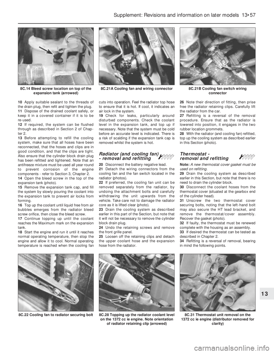
14Open the bleed screw in the top of the
expansion tank (photo).
15Remove the expansion tank cap, and fill
the system by slowly pouring the coolant into
the expansion tank to prevent air locks from
forming.
16Top up the coolant until liquid free from air
bubbles emerges from the radiator bleed
screw orifice, then close the bleed screw.
17Continue topping up until the coolant
reaches the Maximum mark on the expansion
tank.
18Start the engine and run it until it reaches
normal operating temperature, then stop the
engine and allow it to cool. Normal operating
temperature is reached when the cooling fancuts into operation. Feel the radiator top hose
to ensure that it is hot. If cool, it indicates an
air lock in the system.
19Check for leaks, particularly around
disturbed components. Check the coolant
level in the expansion tank, and top up if
necessary. Note that the system must be cold
before an accurate level is indicated. There is
a risk of scalding if the expansion tank cap is
removed whilst the system is hot.
Radiator (and cooling fan)
- removal and refitting Á
20Disconnect the battery negative lead.
21Detach the wiring connectors from the
cooling fan and the fan switch located in the
radiator (photos).
22If preferred, the cooling fan unit can be
removed separately from the radiator, by
undoing the attachment bolts and carefully
withdrawing the unit upwards from the
vehicle. Take care not to damage the radiator
core as it is lifted clear (photo).
23Drain the cooling system as described
earlier in this part of the Section, but note that
it will not be necessary to remove the cylinder
block drain plug.
24Undo the retaining screws and remove
the front grille panel.
25Loosen off the retaining clips and detach
the upper coolant hose and the expansion
hose from the radiator.26Note their direction of fitting, then prise
free the radiator retaining clips. Carefully lift
the radiator from the car.
27Refitting is a reversal of the removal
procedure. Ensure that as the radiator is
lowered into position, it engages in the two
rubber location grommets.
28With the radiator (and cooling fan) refitted,
top up the cooling system as described earlier
in this Section (photo).
Thermostat -
removal and refitting Á
Note: A new thermostat cover gasket must be
used on refitting.
29Drain the cooling system as described
earlier in this Section, but note that there is no
need to drain the cylinder block.
30Disconnect the coolant hoses from the
thermostat cover (situated at the gearbox end
of the cylinder head).
31Unscrew the two thermostat cover
securing bolts, noting that the left-hand bolt
may also secure the HT lead bracket, and
remove the thermostat/cover assembly.
Recover the gasket (photo).
32If faulty, the thermostat must be renewed
complete with the housing as an assembly.
33If desired the thermostat can be tested as
described in Chapter 2.
34Refitting is a reversal of removal, bearing
in mind the following points.
Supplement: Revisions and information on later models 13•57
8C.21B Cooling fan switch wiring
connector8C.21A Cooling fan and wiring connector8C.14 Bleed screw location on top of the
expansion tank (arrowed)
8C.31 Thermostat unit removal on the
1372 cc ie engine (distributor removed for
clarity)8C.28 Topping up the radiator coolant level
on the 1372 cc ie engine. Note orientation
of radiator retaining clip (arrowed)8C.22 Cooling fan to radiator securing bolt
13
Page 194 of 303

39Now use the ohmmeter to check the
resistance of the following components.
Supplementary air valve
40Resistance between the terminals should
be between 40 and 60 ohms at 20ºC (68ºF).
Airflow meter
41Resistance between terminals 5 and 8 of
the potentiometer should be between 330 and
360 ohms at 20ºC (68ºF).
42Resistance between terminals 8 and 9 of
the internal circuit should be between 190 and
210 ohms at 20ºC (68ºF) and between 170
and 190 ohms at 60ºC (140ºF).
Coolant temperature sensor
43At 20ºC (68ºF) the resistance should be
between 2 and 4 k ohms. At 50ºC (122ºF) the
resistance should be between 600 and
900 ohms. At 90ºC (194ºF) the resistance
should be between 100 and 300 ohms.
Fuel injectors
44The winding resistance should be
between 15 and 17 ohms at 20ºC (68ºF).
Throttle position switch
45With the throttle butterfly valve closed,
there should be continuity between ter-
minals 18 and 2, and with the valve fully open,
there should be no continuity between
terminals 18 and 3.
46The throttle position switch should not be
disturbed unless absolutely necessary. If it
has to be removed, then refit it so that themicroswitch is heard to click immediately the
throttle butterfly is opened.
Fuel injection system -
mechanical tests ª
Fuel pump
47To test the pressure of the fuel pump, a
pressure gauge will be required, connected
into the fuel delivery hose.
48Remove the multipin plug from the system
control relay and bridge terminals 87b and 30.
49Turn the ignition switch on. The pump
should operate and indicate a pressure of
between 2.8 and 3.0 bars (40 and 44 lbf/in
2).
50To check the operation of the peak
pressure regulator, pinch the fuel return hose.
If the fuel pressure increases, the regulator
must be faulty, and should be renewed.
51Check that the fuel pressure increases
when, with the engine idling, the accelerator is
depressed sharply.
Supplementary air valve
52With the engine at normal operating
temperature and idling, pinch the
supplementary air valve hose using a pair of
pliers. The engine speed should not drop by
more than 50 rpm. If it does, renew the valve.
Fuel injection system
components -
removal and refitting
ª
53Disconnect the battery before carrying out
any of the following operations.
Air cleaner
54Remove the cover and filter element as
previously described.
55Disconnect the duct from the air cleaner
casing, and then unbolt and remove the
casing. Note that the lower bracket bolt need
not be completely removed, only unscrewed,
due to the design of the bracket. The air
cleaner metal duct is routed over the top of
the radiator (photos).
Airflow meter
56Release the securing clip and disconnect
the air intake duct (photo).
57Release the securing clip and disconnect
the air outlet duct (photo).
58Disconnect the wiring plug.
59Unscrew the fixing screws and remove
the airflow meter from its mounting bracket.
Supplement: Revisions and information on later models 13•69
9C.55B Removing the air cleaner casing
upper bracket9C.55A Disconnecting the duct from the air
cleanerFig. 13.43 System control relay connector
plug terminals 1301 cc Turbo ie engine
(Sec 9C)
9C.57 Air outlet duct securing clip removal
from airflow meter
9C.55C Air cleaner casing lower bracket
and bolt (arrowed)
9C.56 Air intake duct at airflow meter
(securing clip arrowed)9C.55D Air cleaner metal duct over
radiator
13
Page 196 of 303
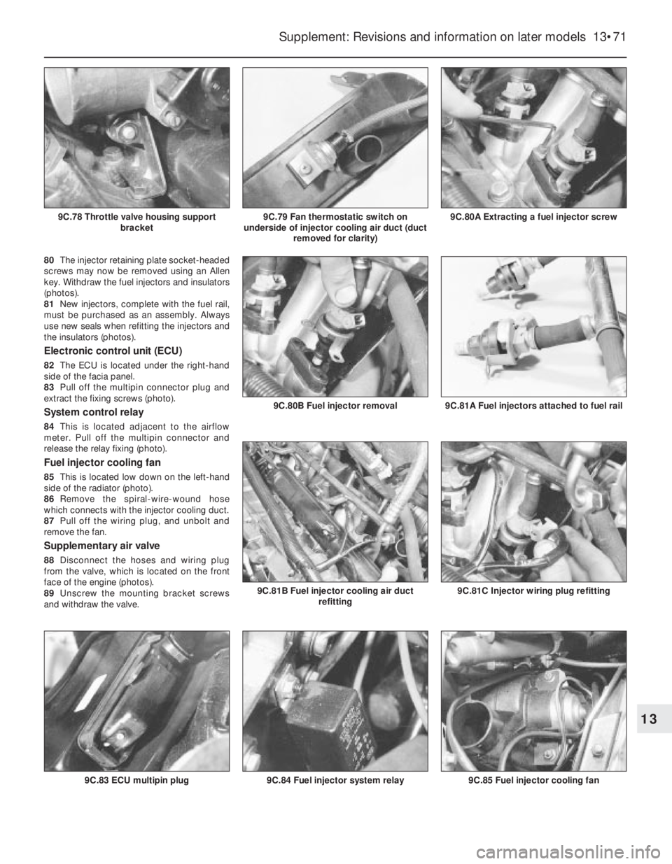
80The injector retaining plate socket-headed
screws may now be removed using an Allen
key. Withdraw the fuel injectors and insulators
(photos).
81New injectors, complete with the fuel rail,
must be purchased as an assembly. Always
use new seals when refitting the injectors and
the insulators (photos).
Electronic control unit (ECU)
82The ECU is located under the right-hand
side of the facia panel.
83Pull off the multipin connector plug and
extract the fixing screws (photo).
System control relay
84This is located adjacent to the airflow
meter. Pull off the multipin connector and
release the relay fixing (photo).
Fuel injector cooling fan
85This is located low down on the left-hand
side of the radiator (photo).
86Remove the spiral-wire-wound hose
which connects with the injector cooling duct.
87Pull off the wiring plug, and unbolt and
remove the fan.
Supplementary air valve
88Disconnect the hoses and wiring plug
from the valve, which is located on the front
face of the engine (photos).
89Unscrew the mounting bracket screws
and withdraw the valve.
Supplement: Revisions and information on later models 13•71
9C.80A Extracting a fuel injector screw9C.79 Fan thermostatic switch on
underside of injector cooling air duct (duct
removed for clarity)
9C.85 Fuel injector cooling fan9C.84 Fuel injector system relay9C.83 ECU multipin plug
9C.81C Injector wiring plug refitting9C.81B Fuel injector cooling air duct
refitting
9C.81A Fuel injectors attached to fuel rail9C.80B Fuel injector removal
13
9C.78 Throttle valve housing support
bracket
Page 203 of 303

c) If the engine develops a misfire, do not
drive the car at all (or at least as little as
possible) until the fault is cured - the
misfire will allow unburned fuel to enter
the converter, which will result in its
overheating, as noted above.
d) DO NOT push- or tow-start the car - this
will soak the catalytic converter in
unburned fuel, causing it to overheat
when the engine does start - see b)
above.
e) DO NOT switch off the ignition at high
engine speeds - if the ignition is switched
off at anything above idle speed,
unburned fuel will enter the (very hot)
catalytic converter, with the possible risk
of its igniting on the element and
damaging the converter.
f) DO NOT use fuel or engine oil additives -
these may contain substances harmful to
the catalytic converter.
g) DO NOT continue to use the car if the
engine burns oil to the extent of leaving a
visible trail of blue smoke - the unburned
carbon deposits will clog the converter
passages and reduce its efficiency; in
severe cases the element will overheat.
h) Remember that the catalytic converter
operates at very high temperatures and
the casing will become hot enough to
ignite combustible materials which brush
against it. DO NOT, therefore, park the car
in dry undergrowth, over long grass or
piles of dead leaves.
i) Remember that the catalytic converter is
FRAGILE - do not strike it with tools
during servicing work, take great care
when working on the exhaust system,
ensure that the converter is well clear of
any jacks or other lifting gear used to raise
the car and do not drive the car over
rough ground road humps, etc., in such a
way as to ground the exhaust system.
j) In some cases, particularly when the car is
new and/or is used for stop/start driving, a
sulphurous smell (like that of rotten eggs)
may be noticed from the exhaust. This is
common to many catalytic
converter-equipped cars and seems to be
due to the small amount of sulphur found
in some petrols reacting with hydrogen in
the exhaust to produce hydrogen sulphide
(H
2S) gas; while this gas is toxic, it is not
produced in sufficient amounts to be a
problem. Once the car has covered a few
thousand miles the problem should
disappear - in the meanwhile a change of
driving style or of the brand of petrol used
may effect a solution.
k) The catalytic converter, used on a
well-maintained and well driven car,
should last for at least 50 000 miles
(80 000 km) or five years - from this point
on, careful checks should be made at all
specified service intervals on the CO level
to ensure that the converter is still
operating efficiently - if the converter is no
longer effective it must be renewed.
Fuel evaporation control system
- general
76As mentioned earlier, fuel evaporation is
contained within the system. In high outdoor
temperatures, when the vehicle is parked for a
period of time, the fuel in the tank evaporates,
building up pressure. When the pressure builds
up to a predetermined level a vent valve opens
to allow the vapours to pass on to and absorbed
by a carbon filter. However, if extreme pressure
or vacuum should build up, a two way safety
valve opens to allow external venting.
77If the safety valve needs replacing, note
that it must be fitted correctly. The black end
should be connected to the fuel tank and the
blue to the carbon filter.
78The vapours in the carbon filter are
flushed by warm air passing through the filter
on to a ECU controlled vapour cut-off
solenoid.
79The cut-off solenoid is closed when
starting the engine and opens to allow
vapours to be drawn into the inlet manifold,
through a second solenoid. If the cut-off
solenoid needs replacing ensure that the
black arrow on the casing is pointing towards
the inlet manifold.
80The second solenoid, known as an Elbi
solenoid, is closed when the engine is turned
off, thus preventing engine run-on. The side
facing connection is for the inlet manifold
pipe.
PART E:
BOSCH L3.1/2 JETRONIC
FUEL INJECTION SYSTEMS
Warning: Refer to the beginning
of this Section before starting
any work.
Description
1A Bosch L3.1 (or L3.2, as fitted from 1992)
Jetronic fuel injection system is fitted to the
1372 cc Turbo ie engine. The system circuit
and main component locations are shown in
Figs. 13.48 and 13.49.
2The L3.1/2 Jetronic system is a multi-point
fuel injection (MPi) system. It operates in a
similar manner to that of the LE2-Jetronic
system fitted to the 1301 cc Turbo ie engine
described in Part C of this Section. The L3.1/2
system is more sophisticated and has the
ability to provide reasonably efficient engine
operation when system sensors malfunction.
As with the LE2 system, the fuel and air
supply mixture circuits are regulated in
accordance with the electronic control unit
(ECU), but on the L3.1/2 system the control
unit is attached to the upper part of the
airflow meter.
3The ECU analyses the information passed
to it from the system sensors. These signals
are then processed and the air/fuel mixture is
constantly adjusted as required to provide the
13•78 Supplement: Revisions and information on later models
Fig. 13.48 Bosch L3.1 Jetronic fuel injection system - 1372 cc Turbo ie engine (Sec 9E)
1 ECU
1A Diagnostic socket
2 Injection system relay and
fuel pump relay
3 Ignition switch
4 Battery
5 Fuel tank
6 Fuel pump
6A Primary fuel filter7 Coolant temperature
sensor
8 Intake air cooling radiator
(intercooler)
9 Air cleaner
10 Supplementary air valve
11 Throttle position switch
11A Throttle housing
12 Airflow meter12A Intake air temperature
sensor
13 Fuel pressure regulator
14 Fuel rail (to injectors)
15 Secondary fuel filter
16 Injectors
17 Injector cooling fan
18 Thermostatic switch (to
engage injector cooling fan)
Page 230 of 303

Starter motor brushes
(later models) - renewal#
25When renewing the starter motor brushes
on later models, the old brushes will need to
be crushed (in a vice or with a hammer) and
their leads then soldered to the new brushes.
Fuses - later models
26The fuse arrangement is slightly different
on later models, but the circuits protected are
still identified by a symbol. Refer to the
Specifications Section for full details. Note
also the terminal block with plastic cover,
which can be used to isolate the battery from
the electrical system by disconnecting the
leads from the terminals (photos).
Relays (Turbo ie models) -
general
27On Turbo ie models, the relays mounted
in the fuse block are as shown in Fig. 13.103.
Additional relays are located as follows:
Headlamp relay - on lead under main fuse
blockFuel injection system main control relay -
adjacent to airflow meter
Headlamps later models
28The headlamp units fitted on later models
differ according to model, but the bulb and
unit replacement details are generally the
same as described for previous models in
Chapter 9. Note that the rubber cover can
only be fitted with the tab to the top as shown
(photo).
Headlamp beam adjusters for
load compensation - later
models
29Some later models are fitted with
headlamp beam adjusters which allowtemporary resetting to be made (such as
when the car is fully loaded). Access to these
adjusters is made by lifting the bonnet (photo).
30Turn the adjusters anti-clockwise to lower
the beam to the normal level or clockwise to
raise the beam (when the car is unloaded).
Repeat the procedure on the opposite
headlamp unit an equal amount.
31Other later models have separate
horizontal and vertical beam adjusters,
positioned as shown (photos). A load
compensating lever is attached to the
adjusters to enable temporary resetting of the
headlamp beams, without changing the
normal adjustment. Turn the lever to the
appropriate side (right or left) to make the
adjustment as required. The normal setting
Supplement: Revisions and information on later models 13•105
15.26B Battery lead terminal block on the
1301 cc Turbo ie model15.23B Starter motor and wiring
connections on the 1372 cc ie engine
15.31B Headlamp vertical beam alignment
adjuster screw on a 1372 cc ie model. Note
the load compensator lever which is set in
the “O” (normal load) setting position15.31A Headlamp horizontal beam
alignment adjuster screw on a 1372 cc ie
model
15.29 Headlamp beam adjuster on the
999 cc Turbo ie model15.28 Headlamp unit fitted to the 1372 cc ie
model
15.26A Fuse block on the 1301 cc Turbo ie
model
13
Fig. 13.103 Auxiliary fuses and relays on
1301 cc Turbo ie models (Sec 15)
1 Horn relay
2 Heated rear screen relay
3 Foglamps relay
4 Radiator fan relay
5 Electric windows relay
6 Foglamps fuse
7 Radiator fan second speed fuse
8 Fuel injector fan fuse
9 Electric windows fuse
10 Electric fuel pump fuse
Page 238 of 303
18Refitting of all components is a reversal of
removal.
Radiator grille (1301 cc
Turbo ie model) -
removal and refitting
Á
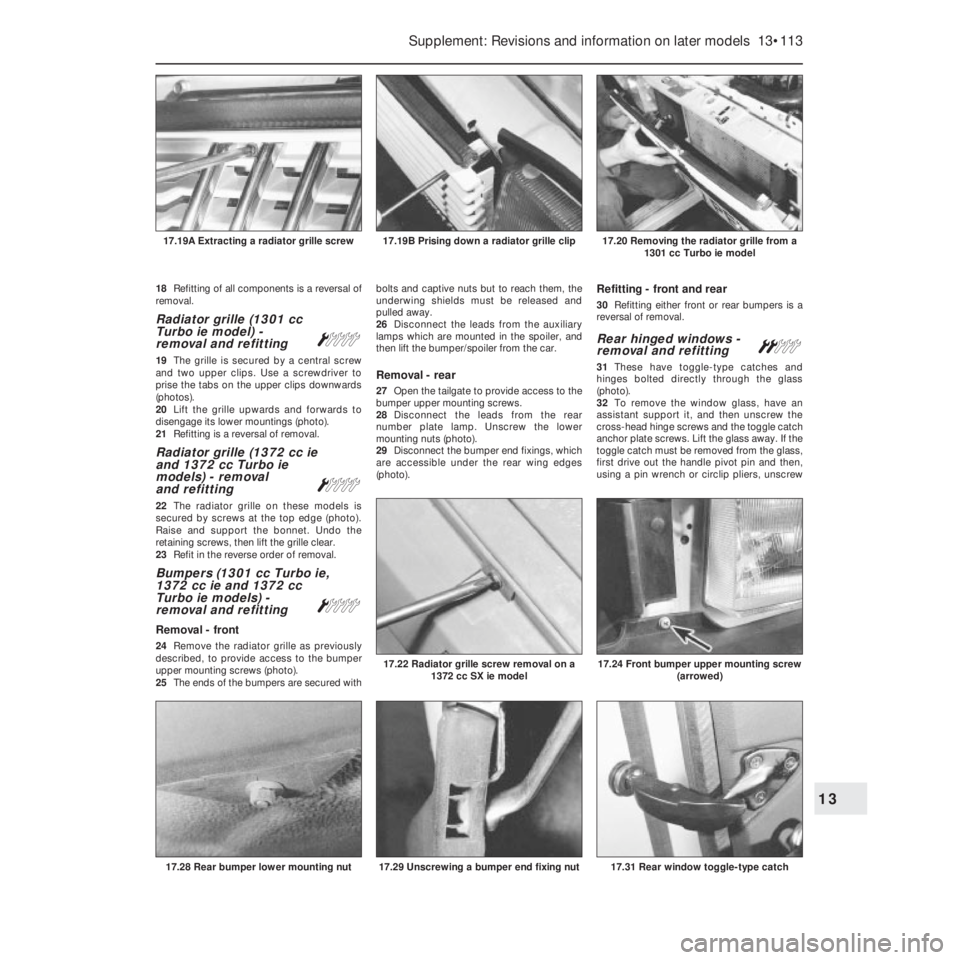
19The grille is secured by a central screw
and two upper clips. Use a screwdriver to
prise the tabs on the upper clips downwards
(photos).
20Lift the grille upwards and forwards to
disengage its lower mountings (photo).
21Refitting is a reversal of removal.
Radiator grille (1372 cc ie
and 1372 cc Turbo ie
models) - removal
and refitting
Á
22The radiator grille on these models is
secured by screws at the top edge (photo).
Raise and support the bonnet. Undo the
retaining screws, then lift the grille clear.
23Refit in the reverse order of removal.
Bumpers (1301 cc Turbo ie,
1372 cc ie and 1372 cc
Turbo ie models) -
removal and refitting
Á
Removal - front
24Remove the radiator grille as previously
described, to provide access to the bumper
upper mounting screws (photo).
25The ends of the bumpers are secured withbolts and captive nuts but to reach them, the
underwing shields must be released and
pulled away.
26Disconnect the leads from the auxiliary
lamps which are mounted in the spoiler, and
then lift the bumper/spoiler from the car.
Removal - rear
27Open the tailgate to provide access to the
bumper upper mounting screws.
28Disconnect the leads from the rear
number plate lamp. Unscrew the lower
mounting nuts (photo).
29Disconnect the bumper end fixings, which
are accessible under the rear wing edges
(photo).
Refitting - front and rear
30Refitting either front or rear bumpers is a
reversal of removal.
Rear hinged windows -
removal and refittingª
31These have toggle-type catches and
hinges bolted directly through the glass
(photo).
32To remove the window glass, have an
assistant support it, and then unscrew the
cross-head hinge screws and the toggle catch
anchor plate screws. Lift the glass away. If the
toggle catch must be removed from the glass,
first drive out the handle pivot pin and then,
using a pin wrench or circlip pliers, unscrew
Supplement: Revisions and information on later models 13•113
17.20 Removing the radiator grille from a
1301 cc Turbo ie model17.19B Prising down a radiator grille clip17.19A Extracting a radiator grille screw
17.31 Rear window toggle-type catch17.29 Unscrewing a bumper end fixing nut
17.24 Front bumper upper mounting screw
(arrowed)17.22 Radiator grille screw removal on a
1372 cc SX ie model
17.28 Rear bumper lower mounting nut
13
Page 240 of 303

Wiring diagrams 14•1
14
Component key for wiring diagrams 1 to 29
Note: Not all the items listed will be fitted to all models
No Description
00200 Alternator with built-in regulator
00500 Battery
01001 Starter motor
01202 Rear front electric window motor
01203 Left front electric window motor
01206 Windscreen wiper motor
01207 Rear screen wiper motor
01252 Right front door locking motor
01253 Left front door locking motor
01254 Right rear door locking motor
01255 Left rear door locking motor
01400 Windscreen washer pump
01401 Rear screen washer pump
01420 Electric fuel pump
01500 Engine cooling fan
01502 Injector cooling fan
01504 Ventilation fan
02001 Engine cut-out solenoid on injection pump
02010 Fuel injector
02011 Fuel injector
02012 Fuel injector
02013 Fuel injector
02015 Supplementary air valve
02210 Accelerator pump outlet cut-out solenoid on
carburettor
02215 Supplementary air valve
02400 Ignition coil
02405 Ignition coil with electronic control unit
02490 Static advance ignition control unit
02492 Microplex ignition system control unit
03000 Insufficient engine oil pressure switch
03002 Right front door ajar switch
03003 Left front door ajar switch
03004 Right rear door ajar switch
03005 Left rear door ajar switch
03006 Handbrake ‘on’ warning switch
03007 Brake stop-lamp switch
03008 Reversing light switch
03028 Radiator thermostatic switch
03029 Coolant overheating warning light thermostatic switch
03034 Injector cooling fan thermostatic switch
03035 Accelerator pump outlet cut-out solenoid thermostatic
switch
03036 Radiator thermostatic switch with two operating ranges
03053 Map reading light switch
03059 Foglamps switch
03060 Rear foglamp switch
03110 Heated rear screen switch
03114 Ventilation fan switch
03123 Air pressure switch
03142 Choke warning light switch
03144 Reset switch
03145 Display switch
03305 Right front door open light push button
03306 Left front door open light push button No Description
03319 Horn push button
03500 Ignition switch
03505 Butterfly valve cut-off switch
03506 Throttle position switch
03530 Right front electric window switch
03531 Left front electric window switch
03546 Rear screen wash/wipe switch
03550 Hazard warning lights switch
04010 Steering column switch unit, direction indicators
04022 Steering column switch unit, headlamps, main beam
and dipped, side lights
04032 Steering column switch unit, windscreen wash/wipe
04214 Fuel injection system control relay
04215 Antiskid system failure relay
04225 Radiator fan 2nd speed engagement relay feed
04241 Foglamps relay feed
04260 Electric windows motor relay feed
04283 Antiskid system relay
04291 Horn relay feed
04292 Heated rear screen relay feed
04441 Dim-dip cut-out 04600 Ignition distributor
04700 Coolant temperature sender unit
04701 Electronic injection coolant temperature sender unit
04720 Oil pressure sender unit
05008 Right headlamp, main beam and dipped with side light
05009 Left headlamp, main beam and dipped with side light
05013 Abnormal fuel consumption sensor
05015 Right foglamp
05016 Left foglamp
05410 Right front direction indicator
05411 Left front direction indicator
05412 Right front side direction indicator
05413 Left front side direction indicator
05640 Rear number plate lamp
05690 Right rear light cluster, sidelight, direction indicator,
brake light, rear foglamp
05691 Left rear light cluster; side light, direction indicator,
brake light, rear foglamp
06000 Centre courtesy light
06026 Map reading light
06076 Ideogram fibre optic light
06080 Heater controls light
06084 Instrument panel light
06300 Sidelights warning light
06305 Main beam headlamps warning light
06310 Rear foglamps warning light
06311 Foglamps warning light
06315 Hazard warning lights warning light
06320 Direction indicators warning light
06335 Insufficient brake fluid level warning light
06336 Handbrake ‘on’ warning light
06343 Insufficient engine oil pressure warning light
06344 Insufficient brake fluid level warning light
06345 Fuel reserve warning light
06350 Coolant overheating warning light
Page 241 of 303

14•2 Wiring diagrams
No Description
06355 Battery charging warning light
06365 Choke warning light
06368 Antiskid system failure lamp
06385 Heated rear screen warning light
06800 Horn
06801 Right horn
06802 Left horn
07000 Coolant level sensor
07001 Engine oil level sensor
07003 Brake fluid level sensor
07015 Right front brake pad wear sensor
07016 Left front brake pad wear sensor
07020 Engine speed sensor
07021 TDC sensor
07022 Anti-knock sensor
07023 Diagnostic socket
07037 Butterfly valve (cut-off) switch
07050 Fuel gauge
07051 Instant fuel consumption gauge (econometer)
07052 Airflow meter
07060 Idle cut-off device
07107 Roadwheel speed sensors
07109 Vacuum switch
07191 Absolute pressure sensor
07192 Vacuum switch
07400 Fuel gauge
07410 Engine oil temperature gauge
07415 Coolant temperature gauge
07420 Engine oil pressure gauge
07430 Tachometer
07460 Clock
07461 Digital clockNo Description
08051 Ignition coil condenser
09000 Dim-dip transformer
09008 Radiator cooling fan 1st speed resistor
09100 Heated rear screen
10022 Cut-off device electronic control unit
10500 Control (fuse) box
10515 Electronic injection control unit
10571 Central locking control unit
10584 Antiskid system ECU
10586 Pressure modulators
59000 Cigar lighter
60000 Instrument panel
60204 Four place fusebox
70090 General earth
70091 General earth
70092 Earth plate
M Electronic control unit
Wire colour codes
A Light blue
B White
C Orange
G Yellow
H Grey
L Blue
M Brown
N Black
R Red
S Pink
V Green
Z Violet
Example of two-colour wire: BN (White/Black) Component key for wiring diagrams 1 to 29 (continued)
Note: Not all the items listed will be fitted to all models