1982 CHEVROLET CAMARO jack
[x] Cancel search: jackPage 69 of 875

GM – CAMARO 1982-1992 – Repair Guide (Checked by WxMax) 69
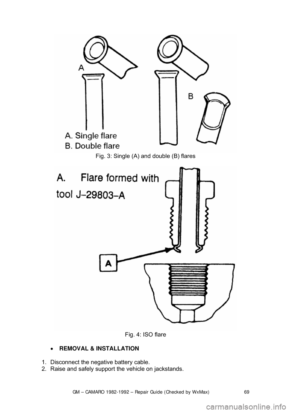
Fig. 3: Single (A) and double (B) flares
Fig. 4: ISO flare
• REMOVAL & INSTALLATION
1. Disconnect the negative battery cable.
2. Raise and safely support the vehicle on jackstands.
Page 119 of 875

GM – CAMARO 1982-1992 – Repair Guide (Checked by WxMax) 119
1. Raise and support the car. Remove the wheel.
2. Remove the caliper by referring to
the Rear Caliper Removal procedure. Pull
the brake disc from the axle.
3. To install, place the rotor ont o the spindle and install caliper.
4. Install the wheel and lower the car.
INSPECTION
1. Raise and support the car. Remove the wheel. Replace wheel nuts to hold rotor in place.
2. Check the rotor surface for wear, sco ring, grooves or rust pitting. Rotor
damage can be corrected by refacing, cons ult your local garage or machine
shop. If the damage exceeds the minimu m thickness, which is stamped on
the rotor, replace the rotor.
3. Using a dial indicator, check the ro tor parallelism at several points around
the circumference. The difference must not vary more than 0.0005 in.
(0.013mm). Make all measur ements at the same distance in from the edge
of the rotor.
4. Using the same dial indicator, meas ure the rotor runout. The runout should
not exceed 0.004 in. (0.10mm).
5. If any of these conditions are not me t, reface or replace the rotor.
PARKING BRAKES
CABLES
REMOVAL & INSTALLATION
FRONT CABLE
Fig. 1: Lever and front cable
1. Raise the car and support it with jackstands.
Page 120 of 875

GM – CAMARO 1982-1992 – Repair Guide (Checked by WxMax) 120
2. Remove the adjusting
nut at the equalizer.
3. Remove the spring retainer clip from the bracket.
4. Lower the car. Remove the upper console cover and lower console rear
screws.
5. Lift the rear of the lower console for access to the cable retainer at the hand
lever.
6. Remove the cable retainer pin, cable retainer, then the cable.
To install:
7. Position the cable retainer pin, cable retainer, then the cable.
8. Install the upper console cover and lo wer console rear screws. Raise the car
and support it with jackstands.
9. Install the spring retainer clip from the bracket.
10. Install the adjusting nut at the equalizer.
11. Adjust the parking br ake. Lower the car.
REAR CABLE
DRUM BRAKES
Fig. 2: Rear cables
CAUTION - Brake shoes may contain asbest os, which has been determined to
be a cancer causing agent. Never clean the brake surfaces with compressed
Page 121 of 875

GM – CAMARO 1982-1992 – Repair Guide (Checked by WxMax) 121
air! Avoid inhaling any dust from any
brake surface! When cleaning brake
surfaces, use a commercially available brake cleaning fluid.
1. Raise the car and support it with jackstands.
2. Loosen the adjusting nut at the equalizer.
3. Disengage the rear cabl e at the connector.
4. Remove the wheel assembly and brake drum.
5. Bend the retainer fingers.
6. Disengage the cable at the brake shoe operating lever.
To install:
7. Engage the cable at the brake shoe operating lever.
8. Bend the retainer fingers.
9. Install the wheel a ssembly and brake drum.
10. Engage the rear cabl e at the connector.
11. Adjust the parking brake by t he adjusting nut at the equalizer.
12. Lower the car.
DISC BRAKES
1. Raise the car and support it with jackstands.
2. Loosen the adjusting nut at the equalizer.
3. Disengage the cable at the connector.
4. Push forward on the caliper parking brak e apply lever. This allows the cable
to be removed from the tang. Then, release the lever.
5. Pull on the caliper parki ng brake apply lever to engage the cable to the tang.
6. Engage the cable at the connector.
7. Adjust the parking brake cable by the adjusting nut at the equalizer.
8. Apply the parking brake 3 times with heavy pressure and repeat adjustment.
9. Lower the car.
ADJUSTMENT
The parking brake cable is adjustable only on 1982-89 vehicles. All 1990-92
vehicles feature a self- adjusting parking brake.
REAR DRUM BRAKES
1. Depress the parking brake leve r exactly two ratchet clicks.
2. Raise the rear of the vehicl e and support safely with jackstands.
3. Tighten the brake cable adjusting nut until the left rear wheel can be turned
rearward with both hands, but locks when forward rotation is attempted. \
4. Release the parking brake le ver; both rear wheels must turn freely in either
direction without brake drag.
5. Lower the vehicle.
Page 288 of 875

GM – CAMARO 1982-1992 – Repair Guide (Checked by WxMax) 288
members which smoothly bring gear and
shaft to the same speed before the
toothed dog clutches are engaged.
ADJUSTMENT
LINKAGE
4-SPEED TRANSMISSION
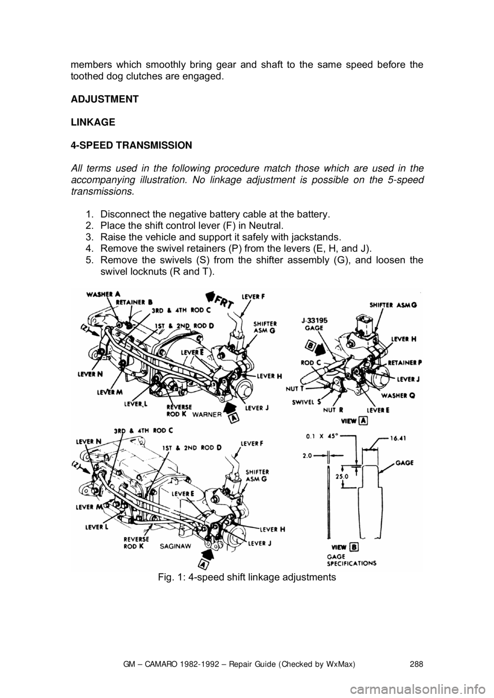
All terms used in the following procedure match those which are used in the
accompanying illustration. No linkage adjustment is possible on the 5-speed
transmissions.
1. Disconnect the negative batte ry cable at the battery.
2. Place the shift control lever (F) in Neutral.
3. Raise the vehicle and support it safely with jackstands.
4. Remove the swivel retainers (P) from the levers (E, H, and J).
5. Remove the swivels (S) from the shifter assembly (G), and loosen the
swivel locknuts (R and T).
Fig. 1: 4-speed shift linkage adjustments
Page 292 of 875

GM – CAMARO 1982-1992 – Repair Guide (Checked by WxMax) 292
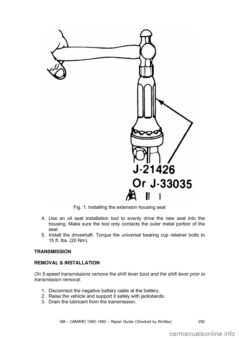
Fig. 1: Installing the extension housing seal
4. Use an oil seal installation tool to evenly drive the new seal into the
housing. Make sure the tool only cont acts the outer metal portion of the
seal.
5. Install the driveshaft. Torque the uni versal bearing cup retainer bolts to
15 ft. lbs. (20 Nm).
TRANSMISSION
REMOVAL & INSTALLATION
On 5-speed transmissions remove the shif t lever boot and the shift lever prior to
transmission removal.
1. Disconnect the negative batte ry cable at the battery.
2. Raise the vehicle and support it safely with jackstands.
3. Drain the lubricant from the transmission.
Page 293 of 875

GM – CAMARO 1982-1992 – Repair Guide (Checked by WxMax) 293
4. Remove the torque arm from t
he vehicle as outlined under Rear
Suspension in
Suspension & Steering of this repair guide.
5. Mark the driveshaft and the rear ax le pinion flange to indicate their
relationship. Unbolt the rear universal joint straps. Lower the rear of the
driveshaft, being careful to keep the universal joint caps in place.
Withdraw the driveshaft from the transmission and remove it from the
vehicle.
6. Disconnect the speedometer cable a nd the electrical connectors from the
transmission.
7. Remove the exhaust pipe brace.
8. Remove the transmission shifter support attaching bolts from the
transmission.
9. On 4-speed transmissions only, disconnec t the shift linkage at the shifter.
10. Raise the transmission slight ly with a jack, then remove the
crossmember attaching bolts.
11. Remove the transmission mount atta ching bolts, then remove the mount
and crossmember from the vehicle.
12. Remove the transmission attachi ng bolts, then with the aid of an
assistant, move the transmission r earward and downward out of the
vehicle.
To install: 13. Apply a light coating of high temperature grease to the main drive gear
bearing retainer and to the splined por tion of the main drive gear. This
will assure free movement of the clutch and transmission components
during assembly.
14. Install the transmission and secu re with transmission mounting bolts
Torque transmission-to-clutch housing bo lts to 55 ft. lbs. (74 Nm).
15. Install the mount and cr ossmember into the vehicle, then install the
transmission mount attaching bolts. Torque both the mount-to-
crossmember bolts and t he mount-to-transmission bolts to 35 ft. lbs. (47
Nm).
16. Install the crossmember attach ing bolts. Torque the crossmember-to-
body bolts to 35 ft. lbs.
17. On 4-speed transmissions only, connect the shift linkage at the shifter and adjust the shift linkage.
18. Install the transmission shifte r support attaching bolts to the
transmission. Torque shifter bracket-to -extension housing to 25 ft. lbs.
(35 Nm).
19. Install the exhaust pipe brace.
20. Connect the speedometer cable and the electrical connectors to the
transmission.
21. Install the driveshaft into the tr ansmission. Then, align the marks on the
driveshaft and the rear axle pinion fl ange. Bolt the rear universal joint
straps.
22. Install the torque arm into the vehicle.
23. Fill the transmission wi th lubricant. Then install the filler plug and torque
to 15 ft. lbs. (20 Nm).
24. Lower the vehicle.
Page 302 of 875

GM – CAMARO 1982-1992 – Repair Guide (Checked by WxMax) 302
7. To install, reverse the removal
procedures. Torque the master cylinder-
to-cowl brace nuts to 10-15 ft. lbs. (14-20 Nm). Fill master cylinder with
new hydraulic fluid conforming to DO T 3 specifications. Bleed and check
the hydraulic clutch system for leaks.
OVERHAUL 1. Remove the filler cap and drain fl uid from the master cylinder.
2. Remove the reservoir and seal from the master cylinder. Pull back the
dust cover and remove the snapring.
3. Remove the push rod assembly. Usi ng a block of wood, tap the master
cylinder on it to eject the plunger a ssembly from the cylinder bore.
4. Remove the seal (carefully) from the front of the plunger assembly,
ensuring no damage occurs to the plunger surfaces.
5. From the rear of t he plunger assembly, remove the spring, the support,
the seal and the shim.
6. Using clean brake fluid, clean all of the parts.
7. Inspect the cylinder bore and t he plunger for ridges, pitting and/or
scratches, the dust cover for wear and cracking; replace the parts if any
of the conditions exist.
To assemble: 8. Use new seals, lubric ate all of the parts in clean brake fluid, fit the
plunger seal to the plunger and reve rse the disassembly procedures.
9. Insert the plunger assembly, va lve end leading into the cylinder bore
(easing the entrance of the plunger seal).
10. Position the push rod assembly into the cylinder bore, then install a new
snapring to retain the push rod. Install dust cover onto the master
cylinder. Lubricate the inside of t he dust cover with Girling® Rubber
Grease or equivalent.
Be careful not to use any lubricant that will deteriorate rubber dust covers or
seals.
SLAVE CYLINDER
On vehicles equipped with a hydraulic clutch release mechanism, the slave
cylinder is located on the left side of the bellhousing and controls the clutch
release fork operation.
REMOVAL & INSTALLATION
1. Disconnect the negative battery cable.
2. Raise and safely support the front of the vehicle on jackstands.
3. Disconnect the hydraulic line from clutch master cylinder. Remove the
line-to-chassis screw and the c lip from the chassis.
Be sure to plug the line opening to k eep dirt and moisture out of the system.