1982 CHEVROLET CAMARO jack
[x] Cancel search: jackPage 367 of 875

GM – CAMARO 1982-1992 – Repair Guide (Checked by WxMax) 367
5.0L AND 5.7L ENGINES
Fig. 3: Engine mountin g points for the V8
1. Disconnect the negative battery cable.
2. Mark the location of the hood on the hood hinges and remove the hood.
3. Remove the air cleaner.
4. Drain the cooling system.
5. Remove the radiator hoses.
6. Disconnect the transmission cooler li nes, the electrical connectors and
retaining clips at the fan and remove the fan and shroud.
7. Remove the radiator.
8. Remove the accessory drive belt.
9. Disconnect the throttle cable.
10. Remove the plenum extension scr ews and the plenum extension, if
equipped.
11. Disconnect the spark plug wires at the distributor and remove the
distributor.
12. Disconnect the necessary vacuum hoses and wiring.
13. Disconnect the power steering and air conditioning compressors from
their respective brackets and lay them aside.
14. Properly relieve the fuel system pressure. Disconnect the fuel lines.
15. Disconnect the negative battery cable at the engine block.
16. Raise and safely support the vehicle.
17. Remove the exhaust pipes at the exhaust manifolds.
18. Remove the flywheel cover and remove the converter to flywheel bolts.
19. Disconnect the starter wires.
20. Remove the bellhousing bolts and the motor mount through-bolts.
21. Lower the vehicle.
22. Support the transmission with a suitable jack.
Page 368 of 875

GM – CAMARO 1982-1992 – Repair Guide (Checked by WxMax) 368
23. Remove the AIR/converter bracket
and ground wires from the rear of the
cylinder head.
24. Attach a suitable lifting devic e and remove the engine assembly.
To install: 25. Position the engine assembly in the vehicle.
26. Attach the motor mount to engine brackets and lower the engine into
place.
27. Remove the engine lifting device and the transmission jack.
28. Raise and safely support the vehicle.
29. Install the motor mount through-bolts and tighten to 50 ft. lbs. (68 (Nm).
30. Install the bellhousing bolts and tighten to 35 ft. lbs. (47 Nm).
31. On vehicles with automatic transmissi on, install the converter to flywheel
bolts. Tighten the bolts to 46 ft. lbs. ( 63 Nm). Install the flywheel cover.
32. Connect the starter wires and the fuel lines.
33. Connect the exhaust pipe at the exhaust manifold.
34. Lower the vehicle.
35. Connect the necessary wires and hoses.
36. Install the power steering pump and air conditioning compressor in their
respective brackets.
37. Install the radiator, fan and fan sh roud, radiator hoses and heater hoses.
38. Connect the transmission cooler lines and cooling fan electrical
connectors.
39. Install the distributor.
40. Install the plenum ex tension, if equipped.
41. Fill the cooling system with the proper type and quantity of coolant and
the crankcase with the proper type of oil to the correct level.
42. Install the air cleaner and the hood.
43. Connect the negative battery cable, start the engine, check for leaks and
check timing.
Page 421 of 875

GM – CAMARO 1982-1992 – Repair Guide (Checked by WxMax) 421
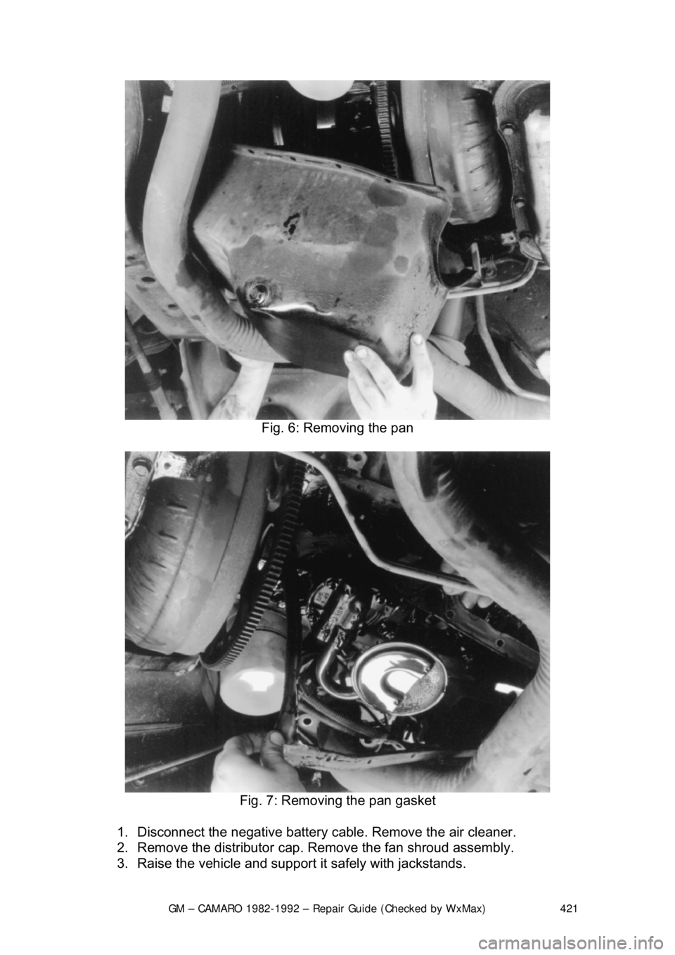
Fig. 6: Removing the pan
Fig. 7: Removing the pan gasket
1. Disconnect the negative battery c able. Remove the air cleaner.
2. Remove the distributor cap. Remove the fan shroud assembly.
3. Raise the vehicle and support it safely with jackstands.
Page 423 of 875

GM – CAMARO 1982-1992 – Repair Guide (Checked by WxMax) 423
22. Fill the engine with engine oil.
23. Start the engine and
check for leaks.
2.5L ENGINE
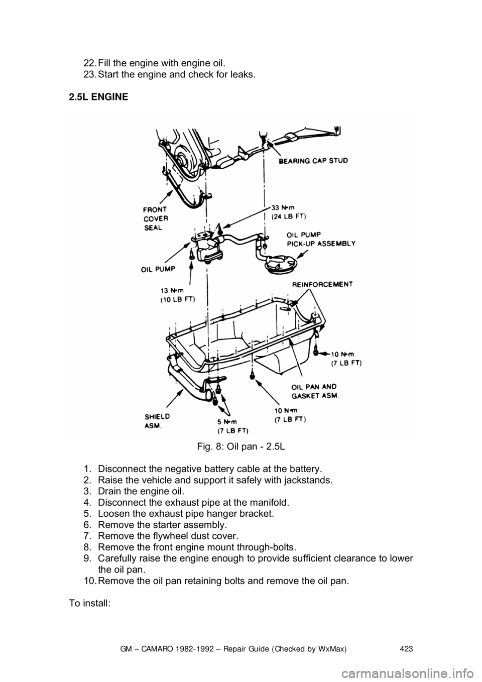
Fig. 8: Oil pan - 2.5L
1. Disconnect the negative batte ry cable at the battery.
2. Raise the vehicle and support it safely with jackstands.
3. Drain the engine oil.
4. Disconnect the exhaust pipe at the manifold.
5. Loosen the exhaust pipe hanger bracket.
6. Remove the starter assembly.
7. Remove the flywheel dust cover.
8. Remove the front engine mount through-bolts.
9. Carefully raise the engine enough to provide sufficient clearance to lower
the oil pan.
10. Remove the oil pan retaining bolts and remove the oil pan.
To install:
Page 451 of 875

GM – CAMARO 1982-1992 – Repair Guide (Checked by WxMax) 451
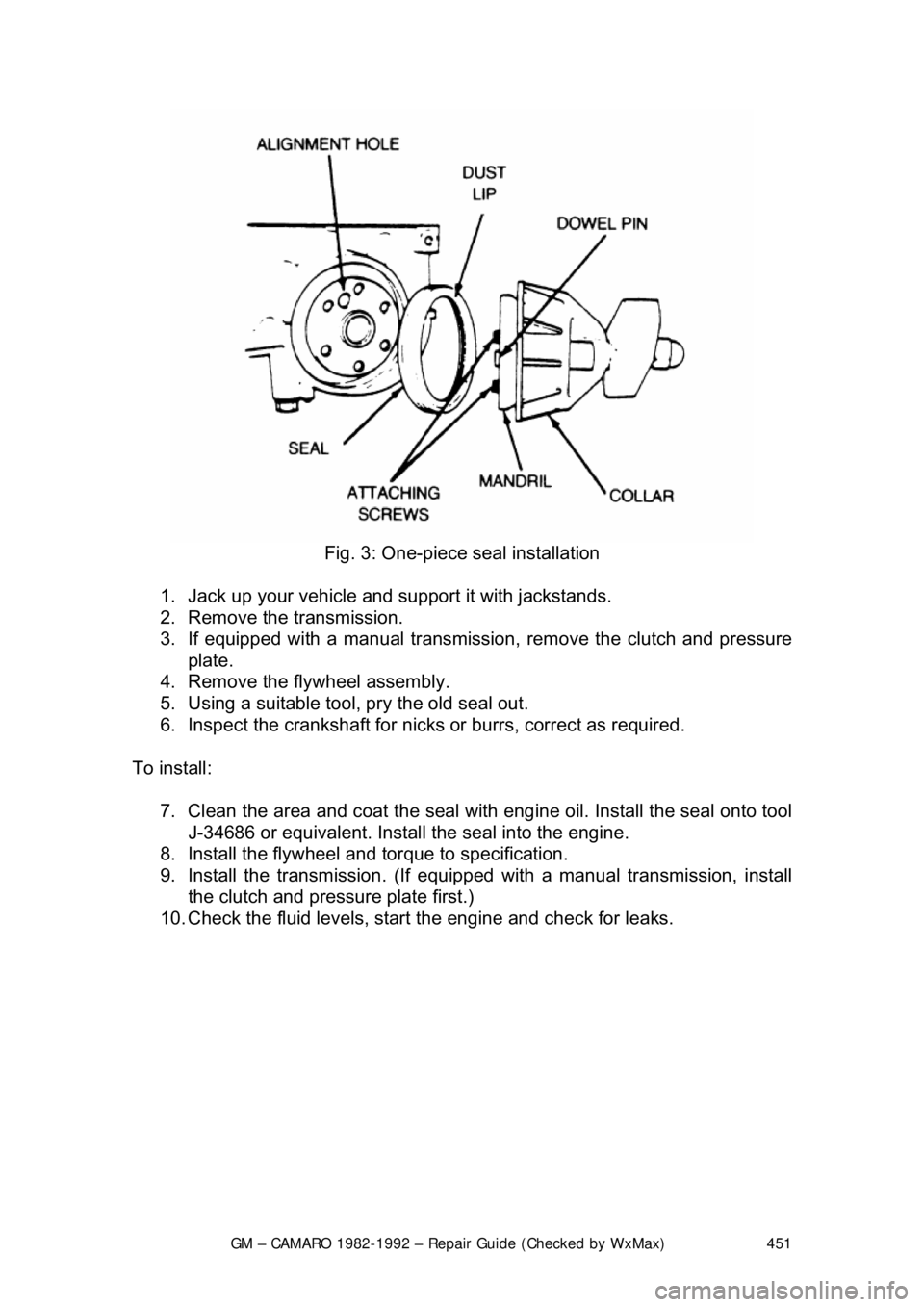
Fig. 3: One-piece seal installation
1. Jack up your vehicle and support it with jackstands.
2. Remove the transmission.
3. If equipped with a manual transmission, remove the clutch and pressure
plate.
4. Remove the flywheel assembly.
5. Using a suitable tool, pry the old seal out.
6. Inspect the crankshaft for nicks or burrs, correct as required.
To install: 7. Clean the area and coat the seal with eng ine oil. Install the seal onto tool
J-34686 or equivalent. Install the seal into the engine.
8. Install the flywheel and torque to specification.
9. Install the transmission. (If equipped with a manual transmission, install
the clutch and pressure plate first.)
10. Check the fluid levels, star t the engine and check for leaks.
Page 490 of 875

GM – CAMARO 1982-1992 – Repair Guide (Checked by WxMax) 490
To replace cast-in type valve guides, t
hey must be drilled out, then reamed to
accept replacement guides. This must be done on a fixture which will allow
centering and leveling off of the original valve seat or guide, otherwise a serious
guide-to-seat misalignment may occur maki ng it impossible to properly machine
the seat.
Replaceable-type guides are pressed into the cylinder head. A hammer and a
stepped drift or punch may be used to inst all and remove the guides. Before
removing the guides, measure the protrusi on on the spring side of the head and
record it for installation. Use the stepped drift to hammer out the old guide from
the combustion chamber side of the head. When installing, determine whether
or not the guide also seal s a water jacket in the head, and if it does, use the
recommended sealing agent. If there is no water jacket, grease the valve guide
and its bore. Use the stepped drift, and hamme r the new guide into the cylinder
head from the spring side of the cylinder head. A stack of washers the same
thickness as the measured protrusion may help the installation process.
VALVE SEATS
Before any valve seat machining can be performed, the guides must be within
factory recommended specifications.
If any machining or replacements were made to the valve guides, the seats
must be machined.
If the seats are in good condition, the va lves can be lapped to the seats, and the
cylinder head assembled. See the valves in formation for instructions on lapping.
If the valve seats are worn, cracked or damaged, they must be serviced by a
machine shop. The valve seat must be per fectly centered to the valve guide,
which requires very accurate machining.
CYLINDER HEAD SURFACE
If the cylinder head is war ped, it must be machined flat. If the warpage is
extremely severe, the head may need to be replaced. In some instances, it may
be possible to straighten a warped head enough to allow machining. In either
case, contact a professional machine shop for service.
CRACKS AND PHYSICAL DAMAGE
Certain cracks can be repaired in both ca st iron and aluminum heads. For cast
iron, a tapered threaded insert is inst alled along the length of the crack.
Aluminum can also use the tapered inse rts, however welding is the preferred
method. Some physical damage can be repaired through brazing or welding.
Contact a machine shop to get expert advice for your particular dilemma.
ASSEMBLY
Page 639 of 875

GM – CAMARO 1982-1992 – Repair Guide (Checked by WxMax) 639
In the HEI system, as in other electr
onic ignition systems, the breaker points
have been replaced wit h an electronic switch - a tr ansistor - which is located
within the ignition module. This switching transistor pe rforms the same function
the points did in a conventi onal ignition system; it simply turns the coil's primary
current on and off at the correct time. Essentially, electronic and conventional
ignition systems operate on t he same principle.
The module which houses the switching transistor is controlled (turned on and
off) by a magnetically gener ated impulse induced in the pickup coil. When the
teeth of the rotating timer align with t he teeth of the pole piece, the induced
voltage in the pickup coil signals the elec tronic module to open the coil primary
circuit. The primary current then decreases, and a high voltage is induced in the
ignition coil secondary windings, which is then directed through the rotor and
high voltage leads (spark plug wires) to fire the spark plugs.
In essence, the pickup coil module system simply replaces the conventional
breaker points and condenser. The condenser found within the distributor is for
radio suppression purposes only and has nothing to do with the ignition
process. The ignition module automatically controls the dwell period, increasing
it with increasing en gine speed. Since dwell is co ntrolled in this manner, it
cannot be adjusted. The module itse lf is non-adjustable/non-repairable and
must be replaced if found defective.
SYSTEM PRECAUTIONS
Before proceeding with troubleshooting, ta ke note of the following precautions:
TIMING LIGHT USE
Care should be exercised when connec ting a timing light or other pick-up
equipment. Do not force anything between the boots and wiring, or through the
silicone jacket. Connections should be made in parallel using an adapter.
Inductive pickup timing lights are the bes t kind to use with the ignition systems
covered by this information.
SPARK PLUG WIRES
The plug wires used with these systems are of a different construction than
conventional wires. When replacing them, make sure you get the correct wires,
since conventional wires will not carry the voltage. Also, handle the wires
carefully to avoid cracking or splitti ng them, and NEVER pierce the wires.
TACHOMETER USE
Not all tachometers will operate or indi cate correctly when used on an HEI or
C
3I system. While some tachometers ma y give a reading, this does not
necessarily mean the reading is correct. In addition, some tachometers hook up
differently from others. If you cannot fi gure out whether or not your tachometer
will work on your car, check with the tachometer manufacturer.
Page 763 of 875

GM – CAMARO 1982-1992 – Repair Guide (Checked by WxMax) 763
•
Jackstands for support.
• Oil filter wrench.
• Spout or funnel for pouring fluids.
• Grease gun for chassis lubrication (unl ess your vehicle is not equipped
with any grease fittings)
• Hydrometer for checking the battery (unless equipped with a sealed,
maintenance-free battery).
• A container for draining oil and other fluids.
• Rags for wiping up the inevitable mess.
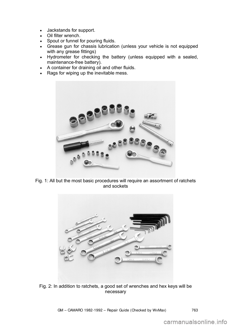
Fig. 1: All but the most basic procedures will require an assortment of ratchets
and sockets
Fig. 2: In addition to ratchets, a good set of wrenches and hex keys will be
necessary