1982 CHEVROLET CAMARO jack
[x] Cancel search: jackPage 850 of 875

GM – CAMARO 1982-1992 – Repair Guide (Checked by WxMax) 850
TURN SIGNAL SWITCH
WARNING - Before attempting any repai
rs involving the steering wheel or
disassembly of it, ensure that the Supple mental Inflatable Restraint (Air Bag)
system is properly disarmed.
REMOVAL & INSTALLATION
STANDARD COLUMNS WITHOUT AIR BAG 1. Remove the steering wheel as pr eviously outlined. Remove the trim
cover.
2. Pry the cover off, and lift the cover off the shaft.
3. Position the U-shaped lockplate co mpressing tool on the end of the
steering shaft and compress the lock plate by turning the shaft nut
clockwise. Pry the wire snapri ng out of the shaft groove.
4. Remove the tool and lift t he lockplate off the shaft.
5. Remove the canceling cam assembly and upper bearing preload spring from the shaft.
6. Remove the turn signal lever. Pu sh the flasher knob in and unscrew it.
On models equipped with a button and a knob, remove the button
retaining screw, then remove the button, spring, and knob.
7. Pull the switch connect or out the mast jacket and tape the upper part to
facilitate switch removal. Attach a l ong piece of wire to the turn signal
switch connector. When in stalling the turn signal switch, feed this wire
through the column first, and then use this wire to pull the switch
connector into position. On tilt wheel s, place the turn signal and shifter
housing in low position and remove the harness cover.
8. Remove the three switch mounting screws. Remove the switch by pulling
it straight up while guiding the wir ing harness cover through the column.
To install: 9. Install the replacement switch by working the connector and cover down
through the housing and under the bracket. On tilt models, the connector
is worked down through the housing, under the bracket, and then the
cover is installed on the harness.
10. Install the switch mounting screw s and the connector on the mast jacket
bracket. Install the column -to-dash trim plate.
11. Install the flasher knob and the turn signal lever.
12. With the turn signal lever in neutral and the fl asher knob out, slide the
upper bearing preload spring, and canc eling cam assembly onto the
shaft.
13. Position the lock plate on the s haft and press it down until a new
snapring can be inserted in the shaft groove. Always use a new snapring
when assembling.
14. Install the cover and the steering wheel.
Page 851 of 875

GM – CAMARO 1982-1992 – Repair Guide (Checked by WxMax) 851
TILT COLUMNS WITHOUT AIR BAG
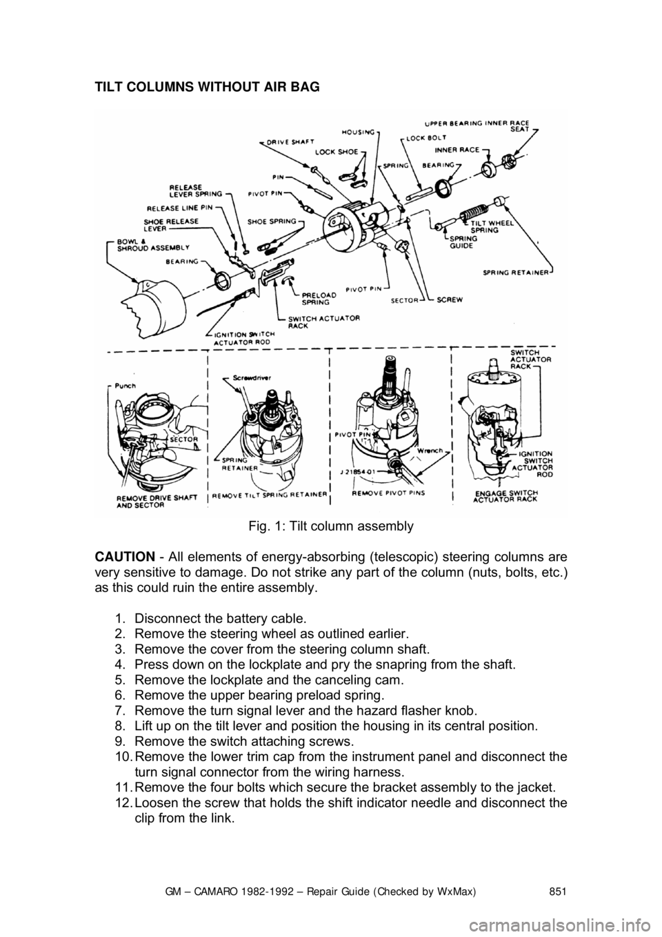
Fig. 1: Tilt column assembly
CAUTION - All elements of energy -absorbing (telescopic) steering columns are
very sensitive to damage. Do not strike any part of the column (nuts, bolts, etc.)
as this could ruin the entire assembly.
1. Disconnect the battery cable.
2. Remove the steering w heel as outlined earlier.
3. Remove the cover from the steering column shaft.
4. Press down on the lockplate and pr y the snapring from the shaft.
5. Remove the lockplate and the canceling cam.
6. Remove the upper bearing preload spring.
7. Remove the turn signal lever and the hazard flasher knob.
8. Lift up on the tilt lever and position the housing in its central position.
9. Remove the switch attaching screws.
10. Remove the lower trim cap from the instrument panel and disconnect the
turn signal connector from the wiring harness.
11. Remove the four bolts which secure the bracket assembly to the jacket.
12. Loosen the screw that holds the sh ift indicator needle and disconnect the
clip from the link.
Page 852 of 875

GM – CAMARO 1982-1992 – Repair Guide (Checked by WxMax) 852
13. Remove the two nuts fr
om the column support bracket while holding the
column in position. Remove the br acket assembly and wire protector
from the wiring, then l oosely install the support column bracket.
14. Tape the turn signal wires at the c onnector to keep them fit and parallel.
15. Carefully remove the turn signal switch and wiring from the column.
To install: 16. Carefully install the turn signal switch and wiring into the column.
17. Remove the tape from the turn signal wires.
18. Install the wire protecto r and, while holding the colu mn in position, install
the two nuts to the colu mn support bracket.
19. Connect the clip to the link and ti ghten the screw that holds the shift
indicator needle.
20. Install the four bolts which secure the bracket assembly to the jacket.
21. Connect the turn signal connector to the wiring harness and install the
lower trim cap to the instrument panel.
22. Install the switch attaching screws.
23. Install the turn signal lever and the hazard flasher knob.
24. Install the upper bear ing preload spring.
25. Install the lockplate and the canceling cam.
26. Press down on the lockplate and inst all the snapring to the shaft using a
new snapring.
27. Install the cover to t he steering column shaft.
28. Install the steering wheel.
29. Connect the battery cable.
Page 859 of 875

GM – CAMARO 1982-1992 – Repair Guide (Checked by WxMax) 859
REMOVAL & INSTALLATION
PITMAN ARM
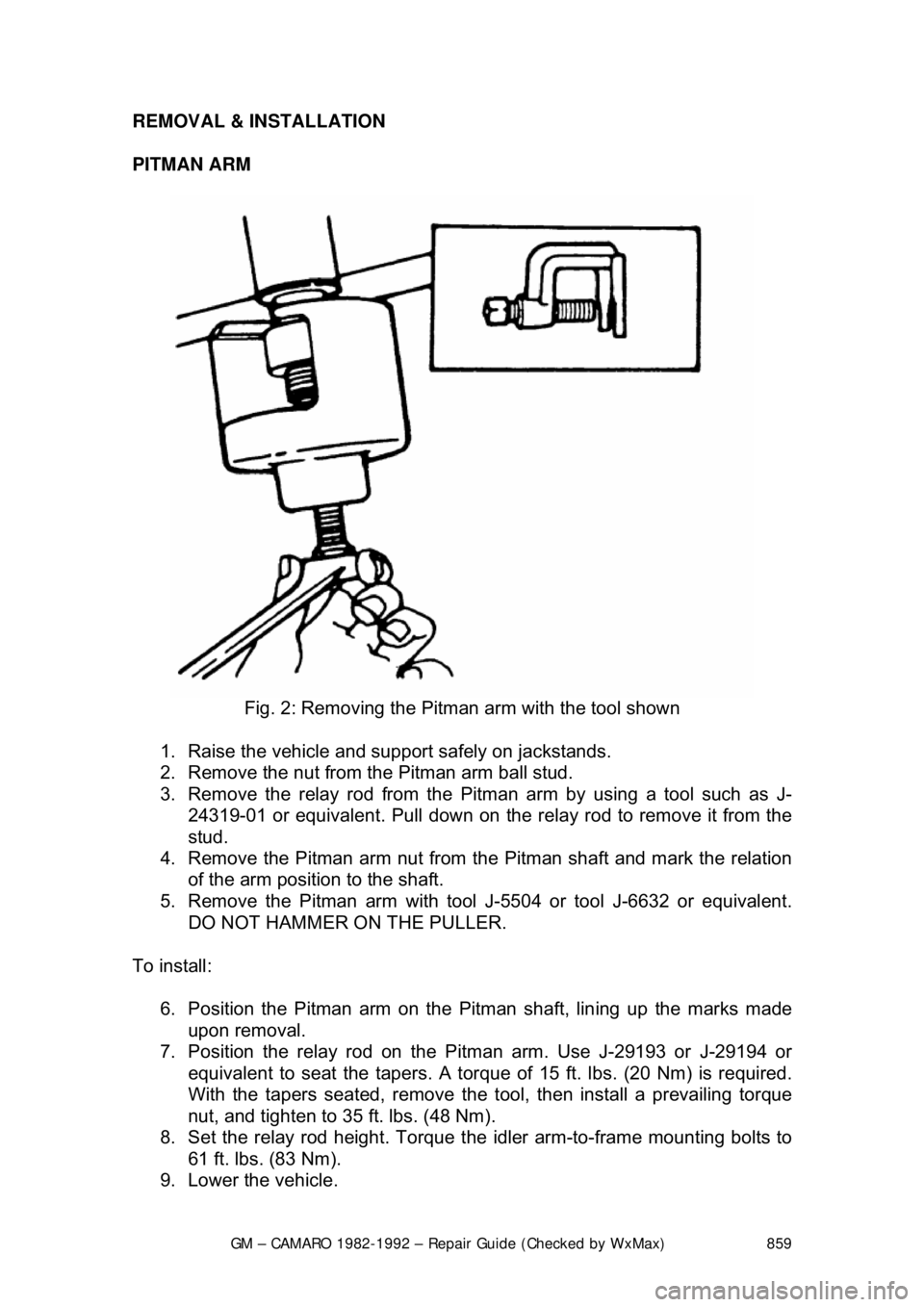
Fig. 2: Removing the Pitman arm with the tool shown
1. Raise the vehicle and support safely on jackstands.
2. Remove the nut from the Pitman arm ball stud.
3. Remove the relay rod from the Pitman arm by us ing a tool such as J-
24319-01 or equivalent. Pull down on the relay rod to remove it from the
stud.
4. Remove the Pitman arm nut from the Pitman shaft and mark the relation
of the arm position to the shaft.
5. Remove the Pitman arm with tool J-5504 or tool J-6632 or equivalent.
DO NOT HAMMER ON THE PULLER.
To install: 6. Position the Pitman arm on the Pitman shaft, lin ing up the marks made
upon removal.
7. Position the relay rod on the Pi tman arm. Use J-29193 or J-29194 or
equivalent to seat the t apers. A torque of 15 ft. lb s. (20 Nm) is required.
With the tapers seated, remove the t ool, then install a prevailing torque
nut, and tighten to 35 ft. lbs. (48 Nm).
8. Set the relay rod height. Torque t he idler arm-to-frame mounting bolts to
61 ft. lbs. (83 Nm).
9. Lower the vehicle.
Page 860 of 875

GM – CAMARO 1982-1992 – Repair Guide (Checked by WxMax) 860
Idler Arm
1. Raise the vehicle and support safely on jackstands.
2. Remove the idler arm to fr ame nuts, washers, and bolts.
3. Remove the nut from the idle r arm to relay rod ball stud.
4. Remove the relay rod from t he idler arm by using J-24319-01 or
equivalent.
5. Remove the idler arm.
To install: 6. Position the idler arm on the fr ame and LOOSELY install the mounting
bolts, washers and nuts.
7. Install the relay rod to the idler a rm, making certain seal is on the stud.
Use J-29193 or J-29194 or equivalent to seat the tapers. A torque of 15
ft. lbs. (20 Nm) is required. With the tapers seated, remove the tool, then
install a prevailing torque nut, and ti ghten to 35 ft. lbs. (48 Nm).
8. Set the relay rod height. Torque t he idler arm-to-frame mounting bolts to
61 ft. lbs. (83 Nm).
9. Lower the vehicle.
RELAY ROD
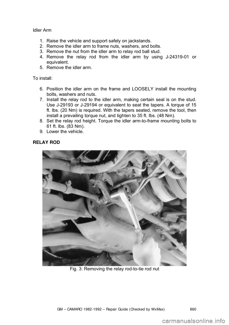
Fig. 3: Removing the relay rod-to-tie rod nut
Page 862 of 875

GM – CAMARO 1982-1992 – Repair Guide (Checked by WxMax) 862
During production, the installe
d position of the relay rod is carefully controlled to
assure that the rod is at the proper height. Both the left end and the right end of
the relay rod must be held at the sa me height. The side-to-side height is
controlled by adjusting the pos ition of the idler arm
Whenever disconnecting the rela y rod assembly, it is important to first scribe the
position of the idler arm-to-frame, and to reinstall the idler arm in the same
position. Be sure to prevent the idler support from turning in the bushing, since
that motion could result in improper relay rod height.
Whenever replacing the relay rod, or the idler arm, or the Pitman arm, it is
mandatory to establish the correct height.
1. Raise the vehicle and support safely on jackstands.
2. Remove the inner ends of the tie rods from the relay rod.
3. Remove the nut from the relay rod ball stud attachment at Pitman arm.
4. Detach the relay rod from the Pitm an arm by using tool such as J-24319-
01 or equivalent. Shift the steering lin kage as required to free the Pitman
arm from the relay rod.
5. Remove the nut from the idler arm and remove the relay rod from the
idler arm.
To install: 6. Install the relay rod to idler arm, ma king certain idler stud seal is in place.
Use J-29193 or J-29194 or equivalent to seat the tapers. A torque of 15
ft. lbs. (20 Nm) is required. With the tapers seated, remove the tool, then
install a prevailing torque nut, and ti ghten to 35 ft. lbs. (48 Nm).
7. Raise the end of the rod and insta ll on the Pitman arm. Use J-29193 or J-
29194 or equivalent to seat the tapers. A torque of 15 ft. lbs. (20 Nm) is
required. With the tapers seated, remove the tool, then install a prevailing
torque nut, and tighten to 35 ft. lbs. (48 Nm).
8. Install the tie rod ends to the re lay rod. Lubricate the tie rod ends.
9. Install the damper , if equipped.
10. Set the relay rod height. Torque t he idler arm-to-frame mounting bolts to
61 ft. lbs. (83 Nm).
11. Lower the vehicle.
12. Check and, if necessary, adjust front end alignment.
Page 863 of 875

GM – CAMARO 1982-1992 – Repair Guide (Checked by WxMax) 863
TIE ROD ENDS
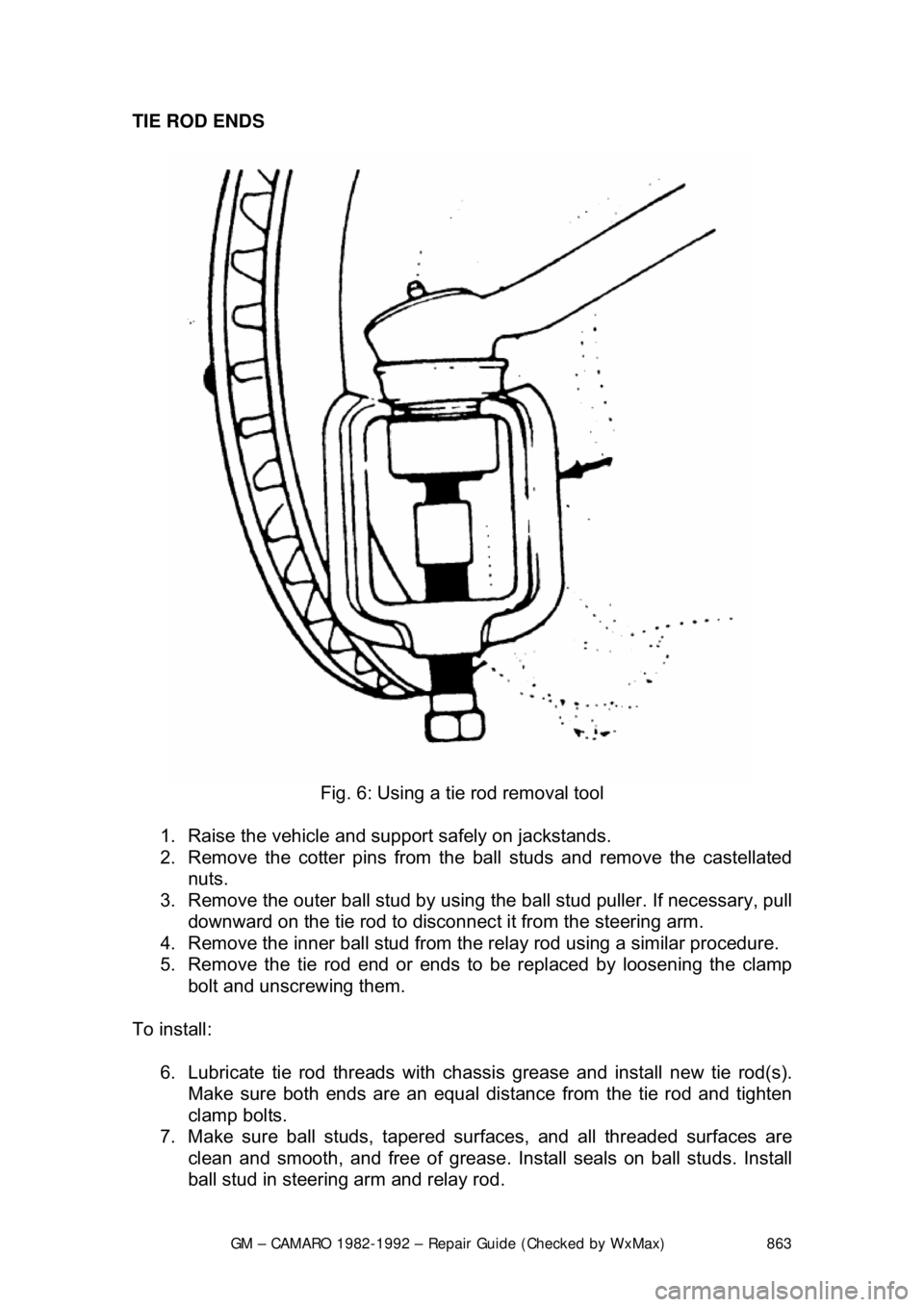
Fig. 6: Using a tie rod removal tool
1. Raise the vehicle and support safely on jackstands.
2. Remove the cotter pins from the ball studs and remove the castellated
nuts.
3. Remove the outer ball stud by usi ng the ball stud puller. If necessary, pull
downward on the tie rod to disconnec t it from the steering arm.
4. Remove the inner ball stud from the relay rod using a similar procedure.
5. Remove the tie rod end or ends to be replaced by loosening the clamp
bolt and unscrewing them.
To install: 6. Lubricate tie rod threads with chassi s grease and install new tie rod(s).
Make sure both ends are an equal di stance from the tie rod and tighten
clamp bolts.
7. Make sure ball studs, tapered surf aces, and all threaded surfaces are
clean and smooth, and free of grease. Install seals on ball studs. Install
ball stud in steering arm and relay rod.