1982 CHEVROLET CAMARO ECU
[x] Cancel search: ECUPage 28 of 875

GM – CAMARO 1982-1992 – Repair Guide (Checked by WxMax) 28
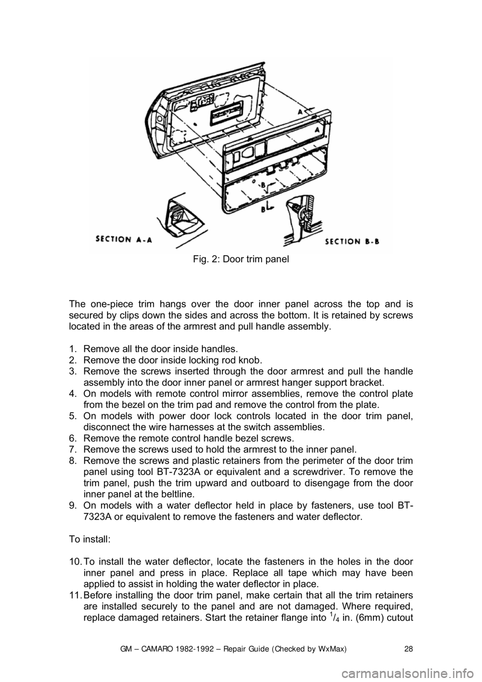
Fig. 2: Door trim panel
The one-piece trim hangs over the door inner panel across the top and is
secured by clips down the sides and across the bottom. It is retained by screws
located in the areas of the armrest and pull handle assembly.
1. Remove all the door inside handles.
2. Remove the door inside locking rod knob.
3. Remove the screws inserted through the door armrest and pull the handle
assembly into the door inner panel or armrest hanger support bracket.
4. On models with remote control mirror assemblies, remove the control plate
from the bezel on the trim pad and remo ve the control from the plate.
5. On models with power door lock contro ls located in the door trim panel,
disconnect the wire harnesses at the switch assemblies.
6. Remove the remote control handle bezel screws.
7. Remove the screws used to hold the armrest to the inner panel.
8. Remove the screws and plastic retainer s from the perimeter of the door trim
panel using tool BT-7323A or equivalent and a screwdriver. To remove the
trim panel, push the trim upward and out board to disengage from the door
inner panel at the beltline.
9. On models with a water deflector held in place by fasteners, use tool BT-
7323A or equivalent to remove th e fasteners and water deflector.
To install:
10. To install the water deflector, locate the fasteners in the holes in the door
inner panel and press in place. R eplace all tape which may have been
applied to assist in holding t he water deflector in place.
11. Before installing the door trim panel, make certain that all the trim retainers
are installed securely to the panel and are not damaged. Where required,
replace damaged retainers. St art the retainer flange into
1/4 in. (6mm) cutout
Page 36 of 875

GM – CAMARO 1982-1992 – Repair Guide (Checked by WxMax) 36
2. Raise the window to half-
up position and hold in place by inserting a rubber
wedge door stops at the front and r ear of the window between window and
inner panel.
3. Remove the rear guide channel and inner panel cam channel.
4. Punch out the center pins of the r egulator rivets; then drill out the rivets
using a
1/4 in. (6mm) drill bit.
5. Move the regulator rear ward and disconnect wire harness from the motor (if
equipped). Disengage the roller on the re gulator lift arm from glass sash
channel.
6. Remove the regulator thr ough the rear access hole.
CAUTION - If electric motor removal from t he regulator is required, the sector
gear must be locked in positi on. The regulator lift arm is under tension from the
counterbalance spring and could cause personal injury if the sector gear is not
locked in position.
7. Drill a hole through the r egulator sector gear and backplate and install a bolt
and nut to lock the sector gear in position.
8. Using a
3/16 in. (5mm) drill bit, drill out the motor attaching rivets and remove
the motor from the regulator.
To install:
9. To install the motor to the regulator, use a rivet tool J-29022 or equivalent,
and install
3/16 in. (5mm) rivets or 3/16 in. (5mm) nuts and bolts. Remove bolt
and nut used to secure the sector gear in position.
10. Place the regulator th rough the rear access hole into the door inner panel. If
electric regulator is being installed, connect the wire connector to motor prior
to installing the regulat or to the inner panel.
11. Locate the lift arm roller in to the glass sash channel.
12. Using rivet tool J-29022 or equivalent, rivet the regulator to the inner panel
of the door using
1/4 in. (6mm) 1/2 in. (13mm) aluminum peel type rivets (part
No. 9436175 or equivalent). If rivet tool is not available, use the following nut
and bolt method:
a. Install U-clips on the regulator at the attaching locations. Be sure to
install the clips with clinch nuts on the outboard side of the regulator.
b. Locate the regulator in the door inner panel. If the electric regulator is
being installed, connect the wire connec tor to the regulator motor.
c. Locate the lift arm roller in the glass sash channel.
d. Align the regulator with clinch nuts to holes in the inner panel.
e. Attach the regulator (and mo tor) to the door inner panel with
1/4-20 x 1/2
in. screws (part No. 9 419723 or equivalent) into 1/4 in. (6mm) nuts with
integral washers. Tighten the screw to 90-125 inch lbs. (10-14 Nm)
torque.
13. Install the inner panel cam channel and rear guide channel.
14. Remove the rubber wedge door stops at the front and rear of the window
between window and inner panel.
15. Install the inner panel water deflector and the door trim panel.
Page 40 of 875

GM – CAMARO 1982-1992 – Repair Guide (Checked by WxMax) 40
INSIDE REAR VIEW MIRROR
INSTALLATION
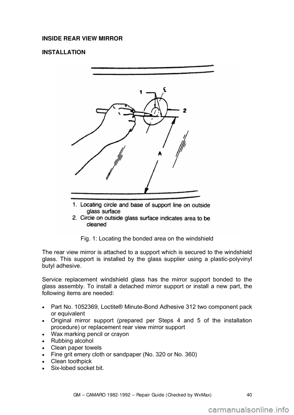
Fig. 1: Locating the bonded area on the windshield
The rear view mirror is attached to a s upport which is secured to the windshield
glass. This support is inst alled by the glass supplier using a plastic-polyvinyl
butyl adhesive.
Service replacement windshield glass has the mirror support bonded to the
glass assembly. To install a detached mi rror support or install a new part, the
following items are needed:
• Part No. 1052369, Loctite® Minute-B ond Adhesive 312 two component pack
or equivalent
• Original mirror support (prepared per Steps 4 and 5 of the installation
procedure) or replacement rear view mirror support
• Wax marking pencil or crayon
• Rubbing alcohol
• Clean paper towels
• Fine grit emery cloth or sandpap er (No. 320 or No. 360)
• Clean toothpick
• Six-lobed socket bit.
Page 45 of 875

GM – CAMARO 1982-1992 – Repair Guide (Checked by WxMax) 45
Fig. 5: Seat belt attachment
1. Remove the cover from the anchor plate.
2. Remove the attaching bolt, anchor pl ate and washer from the door pillar.
3. Remove the bolt cover from the rear of the retractor assembly.
4. Remove the bolt retaining the retrac tor to the floor panel and remove the
retractor.
5. Remove the buckle assemb ly from the floor panel.
6. Remove the cap which conceals t he buckle assembly bolt and remove the
bolt.
7. Remove the seat belt warning wire from the drivers side buckle and remove
the buckle assembly from the vehicle.
8. Installation is the reverse of removal. Tighten all bolts to 31 ft. lbs. (43 Nm).
POWER SEAT MOTOR
REMOVAL & INSTALLATION
1. Remove the front seat assemb ly and place upside down on a clean
protected surface.
2. Disconnect the motor feed wires from the motors.
3. Remove the nut securing the front of the motor support bracket to the
inboard adjuster and withdraw the asse mbly from the adjuster and the
gearnut drives.
4. Disconnect the drive cables from t he motors and complete removal of the
support bracket with the motor attached.
Page 46 of 875

GM – CAMARO 1982-1992 – Repair Guide (Checked by WxMax) 46
5. Grind off the peened ov
er end(s) of the grommet assembly securing the
motor to the support and separate the moto r(s) as required from the support.
To install:
6. Drill out the top end of the grommet assembly using a
3/16 in. (5mm) drill.
7. Install the grommet assembly to the motor support bracket and secure the
motor to the grommet using
3/16 in. (5mm) rivet.
8. Install the support bra cket with the motor attached and connect the drive
cables to the motors.
9. Install the support bracket nuts secu ring the front of the motor support
bracket to the inboard adjuster.
10. Connect the motor feed wires to the motors.
11. Install the front seat assembly.
Page 79 of 875

GM – CAMARO 1982-1992 – Repair Guide (Checked by WxMax) 79
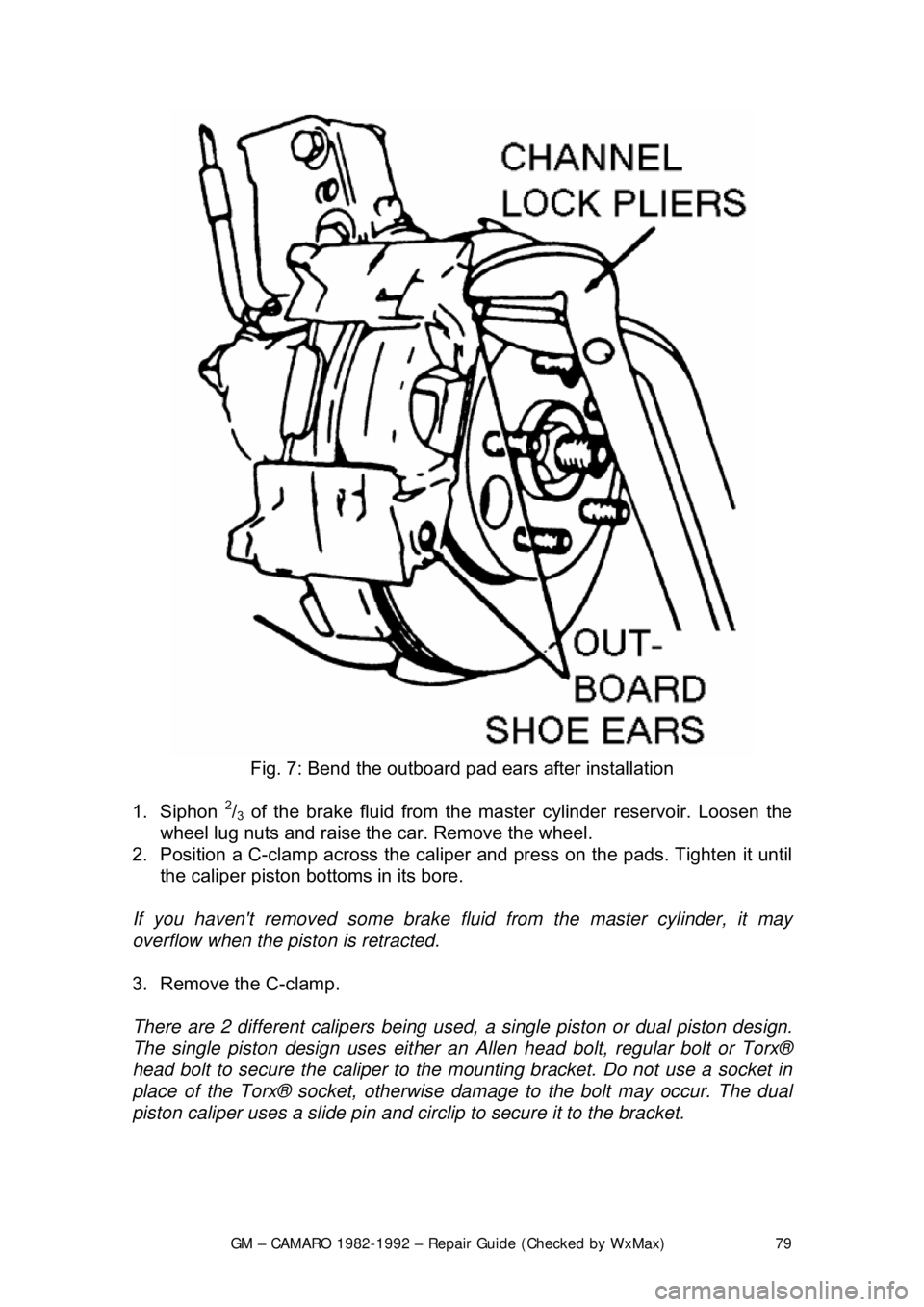
Fig. 7: Bend the outboard pad ears after installation
1. Siphon
2/3 of the brake fluid from the ma ster cylinder reservoir. Loosen the
wheel lug nuts and raise the car. Remove the wheel.
2. Position a C-clamp across the caliper and press on the pads. Tighten it until
the caliper piston bottoms in its bore.
If you haven't removed some brake fluid from the master cylinder, it may
overflow when the piston is retracted.
3. Remove the C-clamp.
There are 2 different calip ers being used, a single pist on or dual piston design.
The single piston design uses either an Allen head bolt, regular bolt or Torx®
head bolt to secure the caliper to the mounting bracket. Do not use a socket in
place of the Torx® socket, otherwise damage to the bolt may occur. The dual
piston caliper uses a slide pin and ci rclip to secure it to the bracket.
Page 114 of 875

GM – CAMARO 1982-1992 – Repair Guide (Checked by WxMax) 114
9. Inspect the guide pins and boots and re
place if corroded, worn or damaged.
Check the inlet fitting bolt for blockage.
10. Install the caliper housing over t he rotor and into the mounting bracket.
Install the 2 caliper guide pin bolts. Tighten the upper caliper guide pin bolt
to 26 ft. lbs. (35 Nm) and the lower gui de pin bolt to 16 ft. lbs. (22 Nm).
11. Connect the parking brake cable to t he caliper bracket and caliper lever.
Install the caliper lever return spring, if removed.
12. Install the inlet fitting, bolt and 2 new washers to the caliper housing. Tighten
the bolt to 22 ft. lbs. (30 Nm).
13. Bleed the brake system.
14. Adjust the parking brake free trav el if the caliper was overhauled.
15. Lower the vehicle and cycle the parking brake.
16. Raise and safely support the vehicle.
17. Inspect the caliper parking brake levers and ensure they are against the
stops on the caliper housing. If the levers are not on their stop, refer to the
parking brake adjustment.
18. Remove the 2 nuts securing the roto r and then install the wheel and tire
assembly. Lower the vehicle.
19. With the engine running, pump the br ake pedal slowly and firmly 3 times to
seat the disc brake pads. Check the hydraulic system for leaks.
OVERHAUL
1982-88 MODELS
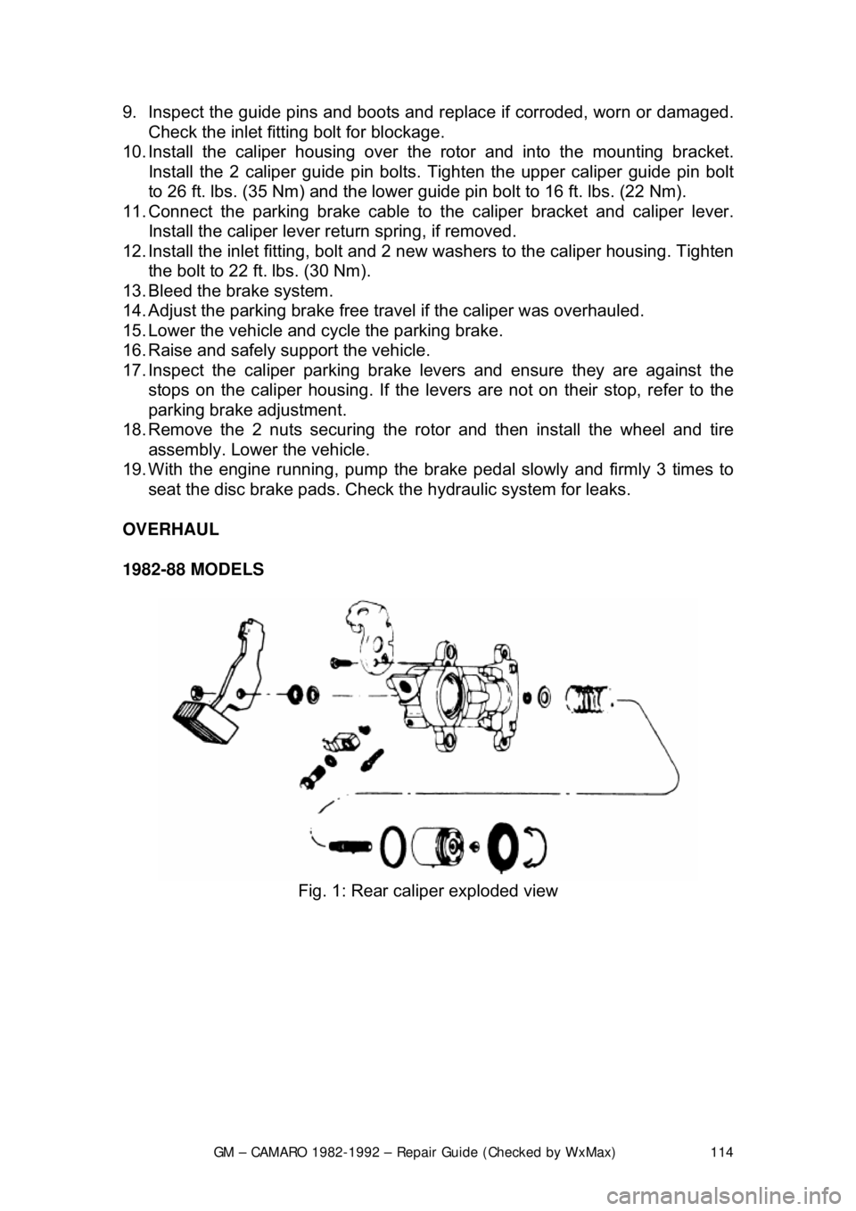
Fig. 1: Rear caliper exploded view
Page 174 of 875

GM – CAMARO 1982-1992 – Repair Guide (Checked by WxMax) 174
Fig. 9: Servo mounting on 1991-1992 Tuned Port Injection engines
ADJUSTMENTS
Do not stretch cables or chains to make pins fit or holes align. This will prevent
the engine from returning to idle.
CABLE TYPE 1. Check that the cable is properly installed and that the throttle is closed to
the idle position.
2. Pull the servo end of the cable towa rd the linkage bracket of the servo.
Place the servo connector in one of the 6 holes in the bracket which
allows the least amount of slack and does not move the throttle linkage.
3. Install the retainer clip. Check that the throttle linkage is still in the idle
position.
ROD WITH SCREW ADJUSTER 1. Inspect the rod assembly for proper attachment to the servo and throttle\
stud. Make certain the throttle is at idle.
2. Adjust the slotted bra cket or the rod to obtain a clearance of 0.02-0.04 in.
(0.5-1.0mm) between the throttle stud and the end of the bracket slot.
3. Install the retainer clip; make certain the throttle is still at idle.
ROD WITH ADJUSTMENT HOLES 1. Inspect the rod to be sure it is securely connected to the servo and
throttle linkage; make certain the throttle is at idle.
2. Install the retainer pin in the hole which provides the least slack between
the servo bracket and the retainer.
3. Check the throttle; it must still be in the idle position.