1982 CHEVROLET CAMARO exhaust
[x] Cancel search: exhaustPage 410 of 875

GM – CAMARO 1982-1992 – Repair Guide (Checked by WxMax) 410
11. Disconnect all electrical connecti
ons from the intake manifold and
cylinder head.
12. If the vehicle has air conditioning, remove the compressor and position it
out of the way. Do not disc onnect the refrigerant lines.
13. Remove the alternator and lay the unit aside. If necessary, remove the
alternator brackets.
14. Remove any other brackets or components mounted on the cylinder
head.
15. Remove the upper radiator hose.
16. Remove the rocker arm cover and back off the rocker arm nuts/bolts and
pivot the rocker arms out of the way so that the pushrods can be
removed. Identify the pushrods so that they can be reinstalled in their
original locations.
17. Remove the cylinder head bolts and cylinder head. Remove the intake
and exhaust manifolds, as required.
To install: 18. Thoroughly clean all mating surfaces of oil, grease and old gasket material. Clean the head bo lts and cylinder block threads, otherwise an
accurate torque specificat ion will not be attained.
19. Install a new gasket on the block mating surface. Position the cylinder
head on the block.
Clean the bolt threads, apply sealing comp ound and install the bolts finger-tight.
20. Tighten the head bolts a little at a time using the correct sequence and
torque to 92 ft lbs. (125 Nm).
21. Install the pushrods and rocker arms . Refer to the procedures described
earlier in this section.
22. Refill the cooling system and check for leaks. The remaining installation
is the reverse of the removal procedure.
2.8L AND 3.1L ENGINES
Fig. 2: Cylinder head bolt torque sequence for all V6 engines
Page 411 of 875

GM – CAMARO 1982-1992 – Repair Guide (Checked by WxMax) 411
1. Disconnect the negative battery cable.
2. Relieve the fuel system pressure
and drain the engine coolant from the
radiator into a suitable container.
3. Remove the intake manifold and the spark plugs.
4. Remove the dipstick tube and bra cket. Raise and support the vehicle
safely. Drain the oil and remove the oil filter. Lower the vehicle.
5. Remove the exhaust manifolds.
6. Remove the drive belt(s).
7. Remove the air conditioning compresso r and bracket, reposition it aside.
Do not disconnect the lines.
8. Remove the power steering pump and bracket, reposition it aside.
9. Remove the alternator and br acket, reposition it aside.
10. Remove the ground cable from the rear of the cylinder head and remove
the engine lift bracket.
11. Remove the rocker arm covers.
12. Loosen the rocker arms until the pushrods can be removed.
13. Remove the cylinder head bolts and remove the cylinder heads.
To install: 14. Clean the gasket mating surfaces of all components. Be careful not to
nick or scratch any surfaces as this will allow leak paths. Clean the bolt
threads in the cylinder bl ock and on the head bolts. Dirt will affect bolt
torque.
15. Place the head gaskets in pos ition over the dowel pins.
16. Install the cylinder heads.
17. Coat the cylinder head bolts th reads with GM sealer 1052080 or
equivalent, and install the bolts. Tight en the bolts in the proper sequence
to:
• 1982-1987 engines: 70 ft lbs. (90 Nm)
• 1988-1992 engines: 1st step: 40 ft lbs. (55 Nm); 2nd step: tighten
an additional 1/4 (90 degree) turn
18. Install the pushrods a nd loosely retain them wit h the rocker arms. Make
sure the lower ends of the pushrods ar e in the lifter seats. Refer to the
rocker arm procedures outlined ea rlier in this section.
19. Install the power steering pump br acket and pump. Do the same for the
air conditioning compressor bracket and compressor.
20. Install the ground cable to t he rear of the cylinder head.
21. Install the exhaust manifolds.
22. Install the dipstick tube and bracket.
23. Install the intake manifold.
24. Install the alternator bracket and alternator.
25. Install the drive belt(s).
26. Install the spark plugs.
27. Fill the cooling system with the proper type and quantity of coolant. Install
a new oil filter and fill the crankca se with the proper type and quantity of
oil.
28. Connect the negative battery cable, star t the vehicle and check for leaks.
Page 416 of 875

GM – CAMARO 1982-1992 – Repair Guide (Checked by WxMax) 416
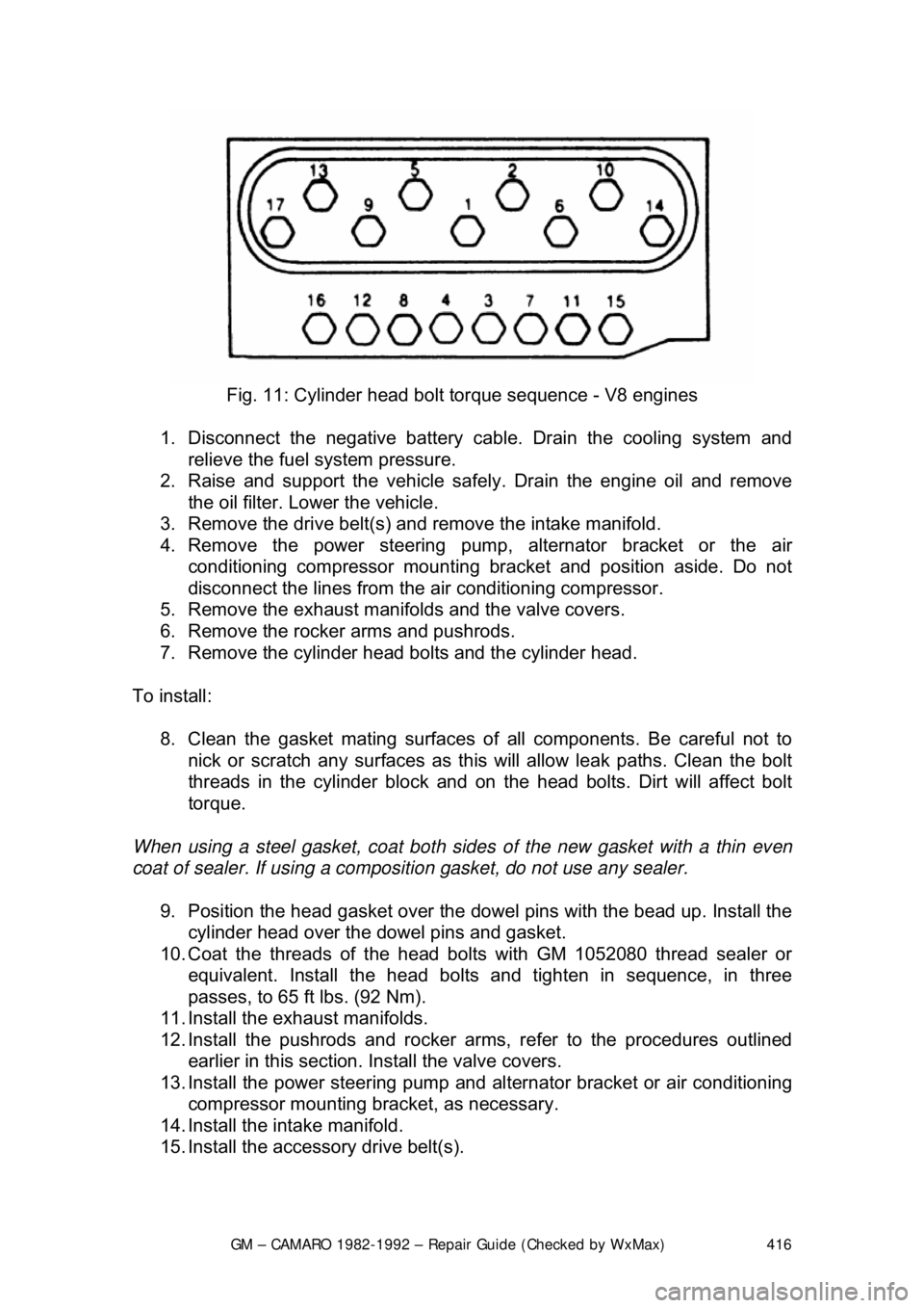
Fig. 11: Cylinder head bolt torque sequence - V8 engines
1. Disconnect the negative battery c able. Drain the cooling system and
relieve the fuel system pressure.
2. Raise and support the vehicle safe ly. Drain the engine oil and remove
the oil filter. Lower the vehicle.
3. Remove the drive belt(s) and remove the intake manifold.
4. Remove the power steering pump, alternator bracket or the air
conditioning compressor mounting br acket and position aside. Do not
disconnect the lines from the air conditioning compressor.
5. Remove the exhaust manifolds and the valve covers.
6. Remove the rocker arms and pushrods.
7. Remove the cylinder head bolts and the cylinder head.
To install: 8. Clean the gasket mating surfaces of all components. Be careful not to
nick or scratch any surfaces as this will allow leak paths. Clean the bolt
threads in the cylinder bl ock and on the head bolts. Dirt will affect bolt
torque.
When using a steel gasket, coat both sides of the new gasket with a thin even
coat of sealer. If using a compos ition gasket, do not use any sealer.
9. Position the head gasket over the dow el pins with the bead up. Install the
cylinder head over the dowel pins and gasket.
10. Coat the threads of the head bo lts with GM 1052080 thread sealer or
equivalent. Install the head bolts and tighten in sequence, in three
passes, to 65 ft lbs. (92 Nm).
11. Install the exhaust manifolds.
12. Install the pushrods and rocker arms, refer to the procedures outlined earlier in this section. Install the valve covers.
13. Install the power steering pump and al ternator bracket or air conditioning
compressor mounting bra cket, as necessary.
14. Install the intake manifold.
15. Install the accessory drive belt(s).
Page 422 of 875

GM – CAMARO 1982-1992 – Repair Guide (Checked by WxMax) 422
4. Drain the engine oil.
CAUTION
- Be sure that the catalytic c onverter is cool before proceeding.
5. Remove the air injection pipe at t he catalytic converter, if applicable.
6. Remove the catalytic converte r hanger bolts. Disconnect the exhaust
pipe at the manifold.
7. Remove the starter bolts, loosen t he starter brace, then lay the starter
aside.
8. Remove the front engine mount through-bolts.
9. Raise the engine enough to provide sufficient clearance for oil pan
removal.
10. Remove the oil pan bolts.
If the front crankshaft throw prohibits remo val of the pan, turn the crankshaft to
position the throw horizontally.
11. Remove the oil pan from the vehicle.
12. Remove the old RTV sealant or gasket from the oil pan and engine
block.
To install: 13. Run a
1/8 in. (3mm) bead of RTV around the oil pan sealing surface or
install a new gasket. Remember to keep the RTV on the INSIDE of the
bolt holes.
14. Install the pan and pan bolts. Torque the pan bolts to:
• 2.8L & 3.1L V6 (M6 x 1 X 16.0 bolts): 6-9 ft. lbs. (8-12 Nm)
• 2.8L & 3.1L V6 (M8 x 1.25 x 14.0 bolts ): 15-22 ft. lbs. (20-30 Nm)
• 1982-84 V8 engine (5/16-18 bolts): 165 inch lbs. (10 Nm)
• 1982-84 V8 engine (1/4-20 bolts): 80 inch lbs. (8 Nm)
• 1985 V8 engine (5/16-18 x 1.44 studs): minimum of 10 inch lbs.
• 1985 V8 engine (stud nuts): 150- 180 inch lbs. (17-20 Nm)
• 1985 V8 engine (1/4-20 x 0.56 bolts): 72-90 inch lbs. (8-10 Nm)
• 1985 V8 engine (1/4-20 x 0.50 x 0.56 studs): 72-90 inch lbs. (8-10
Nm)
• 1986-92 V8 engine (stud nuts): 150-250 inch lbs. (17-28 Nm)
• 1986-92 V8 engine (1/4-20 x 0.56 bolts): 72-130 inch lbs. (8-14
Nm)
• 1986-92 V8 engine (1/4-20 x 0.50 x 0.56 studs ): 72-130 inch lbs.
(8-14 Nm)
15. Lower the engine and install t he front engine mount through-bolts.
Torque bolts to 48 ft. lbs. (65 Nm).
16. Install the starter and starter brace, then secure using starter bolts.
17. Connect the exhaust pipe at the manifo ld. Install the catalytic converter
hanger bolts.
18. Install the air injection pipe at the catalytic converter.
19. Lower the vehicle.
20. Install the fan shroud assembly . Install the distributor cap.
21. Connect the negative battery cable at the battery and air cleaner.
Page 423 of 875

GM – CAMARO 1982-1992 – Repair Guide (Checked by WxMax) 423
22. Fill the engine with engine oil.
23. Start the engine and
check for leaks.
2.5L ENGINE
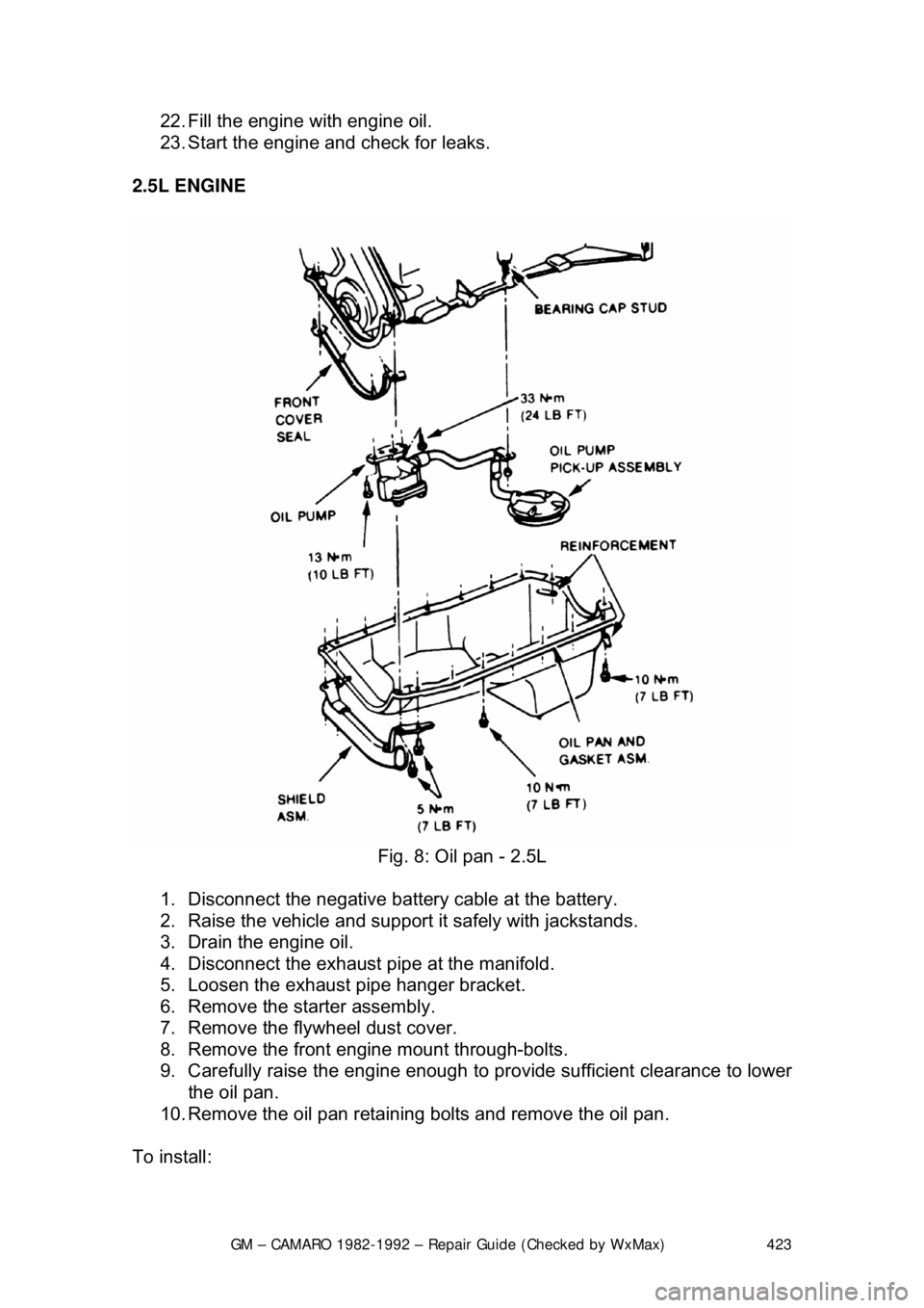
Fig. 8: Oil pan - 2.5L
1. Disconnect the negative batte ry cable at the battery.
2. Raise the vehicle and support it safely with jackstands.
3. Drain the engine oil.
4. Disconnect the exhaust pipe at the manifold.
5. Loosen the exhaust pipe hanger bracket.
6. Remove the starter assembly.
7. Remove the flywheel dust cover.
8. Remove the front engine mount through-bolts.
9. Carefully raise the engine enough to provide sufficient clearance to lower
the oil pan.
10. Remove the oil pan retaining bolts and remove the oil pan.
To install:
Page 424 of 875

GM – CAMARO 1982-1992 – Repair Guide (Checked by WxMax) 424
11. Clean all old RTV from the mating surfaces.
12. Install the rear gasket into the
rear main bearing cap and apply a small
amount of RTV where the gasket engages into the engine block.
13. Install the front gasket.
14. Install the side gaskets, using grease as a retainer. Apply a small amount
of RTV where the side gaskets meet the front gasket.
15. Install the oil pan.
Install the oil pan-to-timing cover bolts la st, as these holes will not align until the
other pan bolts are snug.
16. Torque the pan bolts to 53 inch lbs. (6 Nm) for 1982-1985 models and 90
inch lbs. (10 Nm) for 1986 models.
17. Lower the engine and install the fr ont mount through-bolts. Torque bolts
to 48 ft lbs. (65 Nm).
18. Install the flywheel dust cover.
19. Install the starter assembly.
20. Connect the exhaust pipe at the manifold.
21. Tighten the exhaust pipe hanger bracket.
22. Lower the vehicle.
23. Connect the negative battery cable at the battery.
24. Fill the engine with engine oil and start engine. Check for leaks.
OIL PUMP
REMOVAL & INSTALLATION
Fig. 1: Oil pump - V8
Page 457 of 875

GM – CAMARO 1982-1992 – Repair Guide (Checked by WxMax) 457
EXHAUST SYSTEM
INSPECTION
Safety glasses should be worn at all
times when working on or near the exhaust
system. Older exhaust systems will almost always be covered with loose rust
particles which will shower you when dist urbed. These particles are more than a
nuisance and could injure your eye.
CAUTION - Do NOT perform exhaust repairs or inspection with the engine or
exhaust hot. Allow the system to cool completely before attempting any work.
Exhaust systems are noted for sharp edges , flaking metal and rusted bolts.
Gloves and eye protection ar e required. A healthy supply of penetrating oil and
rags is highly recommended.
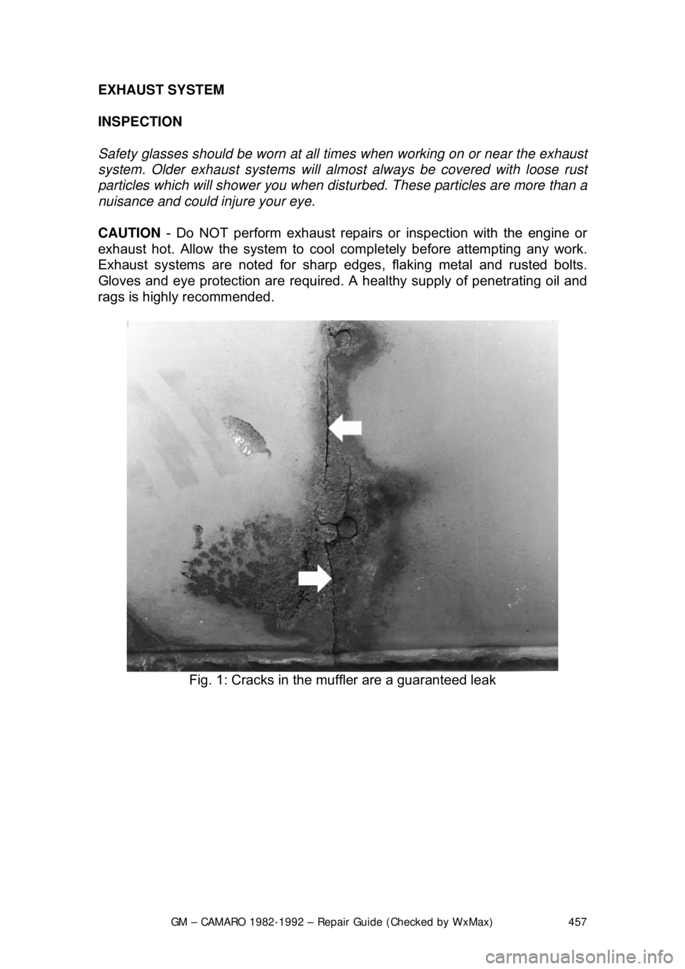
Fig. 1: Cracks in the mu ffler are a guaranteed leak
Page 458 of 875

GM – CAMARO 1982-1992 – Repair Guide (Checked by WxMax) 458
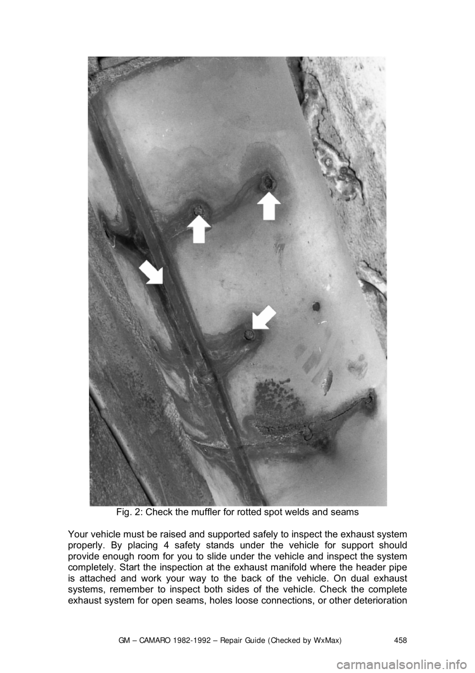
Fig. 2: Check the muffler fo r rotted spot welds and seams
Your vehicle must be rais ed and supported safely to inspect the exhaust system
properly. By placing 4 safety stands under the vehicle for support shoul\
d
provide enough room for you to slide u nder the vehicle and inspect the system
completely. Start the inspection at t he exhaust manifold where the header pipe
is attached and work your way to the back of the vehicle. On dual exhaust
systems, remember to inspect both sides of the vehicle. Check the complete
exhaust system for open seam s, holes loose connections, or other deterioration