1982 CHEVROLET CAMARO power steering fluid
[x] Cancel search: power steering fluidPage 48 of 875

GM – CAMARO 1982-1992 – Repair Guide (Checked by WxMax) 48
BRAKES
BASIC OPERATING PRINCIPLES
Hydraulic systems are used to actuate t he brakes of all modern automobiles.
The system transports the power required to force the frictional surfaces of the
braking system together from the pedal to the individual brake units at each
wheel. A hydraulic system is used for two reasons.
First, fluid under pressure can be carried to all parts of an automobile by small
pipes and flexible hoses without taking up a significant amount of room or
posing routing problems.
Second, a great mechanical advantage can be given to the brake pedal end of
the system, and the foot pressure requi red to actuate the brakes can be
reduced by making the surface area of t he master cylinder pistons smaller than
that of any of the pistons in t he wheel cylinders or calipers.
The master cylinder consists of a flui d reservoir along with a double cylinder
and piston assembly. Double type master cylinders are designed to separate
the front and rear braking systems hydraulic ally in case of a leak. The master
cylinder coverts mechanical motion from t he pedal into hydraulic pressure within
the lines. This pressure is translated back into mechanical motion at th\
e wheels
by either the wheel cylinder (drum brak es) or the caliper (disc brakes).
Steel lines carry the brake fluid to a po int on the vehicle's frame near each of
the vehicle's wheels. The fluid is then ca rried to the calipers and wheel cylinders
by flexible tubes in order to allow for suspension and steering movements.
In drum brake systems, each wheel cylinde r contains two pistons, one at either
end, which push outward in opposite direct ions and force the brake shoe into
contact with the drum.
In disc brake systems, the cylinders ar e part of the calipers. At least one
cylinder in each caliper is used to fo rce the brake pads against the disc.
All pistons employ some type of seal, us ually made of rubber, to minimize fluid
leakage. A rubber dust boot seals the outer end of the cylinder against dust and
dirt. The boot fits around the outer end of the piston on disc brake calipers, and
around the brake actuating rod on wheel cylinders.
The hydraulic system operates as follows : When at rest, the entire system, from
the piston(s) in the master cylinder to t hose in the wheel cylinders or calipers, is
full of brake fluid. Upon app lication of the brake pedal, fluid trapped in front of
the master cylinder piston(s) is forced through the lines to the wheel cylinders.
Here, it forces the pistons outward, in the case of drum brakes, and inward
toward the disc, in the case of disc brakes. The motion of the pistons is
opposed by return springs mounted outside the cylinders in drum brakes, and
by spring seals, in disc brakes.
Page 364 of 875

GM – CAMARO 1982-1992 – Repair Guide (Checked by WxMax) 364
5. Drain the radiator and remove t
he radiator hoses. Disconnect the heater
hoses and the transmission cooler lines.
6. Remove the upper half of the radi ator shroud, if equipped with a manual
transmission. Remove the radiator and fan shroud assembly, if equipped
with an automatic transmission.
7. Disconnect the throttle linkage, includi ng the cruise control detent cable.
8. Remove the air conditioning compressor and lay aside.
Do not disconnect the air conditioning lines.
9. Disconnect the power steering pump and drain the fluid into a suitable
container. Remove the vacuum brake booster line.
10. Remove the distributor cap and spark plug wires.
11. Disconnect the engine electrical connection at the bulkhead connection
and disconnect any necessary vacuum hoses.
12. Working inside the vehicle, re move the right-hand hush panel and
disconnect the ECM harness at the EC M. Raise and safely support the
vehicle. Remove the right fenderwell splash shield and feed the harness
through the fenderwell.
13. Disconnect the exhaust pipes at the exhaust manifolds and remove
exhaust system from the vehicle.
14. Remove the flywheel cover and remo ve the converter bolts, if equipped
with automatic transmission.
15. Disconnect the transmission an d starter wire connections.
16. Remove the bellhousing and t he motor mount through-bolts.
17. Disconnect the clutch fork return spring, if equipped with a manual
transmission. Lower the vehicle.
18. Relieve the fuel system pressu re. Disconnect the fuel lines.
19. Support the transmission with a suit able jack. Attach an engine lifting
device.
20. Remove the engine assembly.
To install: 21. Position the engine assembly in the vehicle.
22. Attach the motor mount to engine br ackets and lower the engine in place.
Remove the engine lifting device and the transmission jack.
23. Raise and support the vehicle safely.
24. Install the motor mount through-bolts and tighten the nuts to specification. Install t he bellhousing bolts and tight en to 35 ft. lbs. (47
Nm).
25. On vehicles with automatic transmissi on, install the converter to flywheel
attaching bolts to 46 ft. lbs. (63 Nm).
26. Install the flywheel splash shield and tighten to 89 inch lbs. (10 Nm).
Install the clutch return spring, if equipped with manual transmission.
27. Connect the starter wires and the fuel lines.
28. Install the exhaust system.
29. Lower the vehicle.
30. Install the power steering pump and the air conditioning compressor.
Page 799 of 875

GM – CAMARO 1982-1992 – Repair Guide (Checked by WxMax) 799
The master cylinder is located in
the left rear section of the engine
compartment. The brake master cylinder consists of an aluminum body and a
translucent nylon reservoir with minimum fill indicators.
1. Check the master cylinder body for cracks. Inspect the area around the
master cylinder for brake fluid. Leaks are indicated if there is at least a
drop of fluid. A damp condition is not normal.
2. Inspect the level of the brake fluid to assure it is at the correct height.
Clean the top of the reservoir cap so t hat all dirt is removed. Remove the
cap(s) or reservoir cover and the reservoir diaphragm.
3. Inspect the brake fluid level. Add clean DOT-3 brake fluid as required to
bring the fluid level to the line located inside the neck of the reservoir fill
opening.
4. Install the reservoir cap.
WARNING - Any sudden decrease in the fluid level indicates a possible leak in
the system and should be check ed out immediately. Do not allow brake fluid to
spill on the vehicle's finish; it will remove the paint. In case of a spill, flush the
area with water and mild soap.
HYDRAULIC CLUTCH SYSTEM
FLUID RECOMMENDATIONS
• 1982-1991 - Delco Supreme II Brake fl uid or an equivalent fluid that
meets DOT-3 specifications
• 1992 - Hydraulic clutch fluid, GM part number 12345347 or equivalent
LEVEL CHECK
The clutch master cylinder is normally lo cated below the brake master cylinder.
The reservoir for it is located right bes ide the brake master cylinder and is made
of translucent nylon. The fl uid level of the reservoir sh ould be kept near the top
of the observation window. Before removing the cap to the reservoir, clean all
dirt from the area. This will prevent syst em contamination due to particles falling
into the reservoir when the caps are removed.
POWER STEERING PUMP
FLUID RECOMMENDATIONS
• GM power steering fluid, or equivalent.
Page 800 of 875

GM – CAMARO 1982-1992 – Repair Guide (Checked by WxMax) 800
LEVEL CHECK
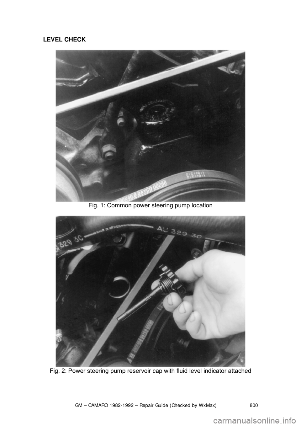
Fig. 1: Common power steering pump location
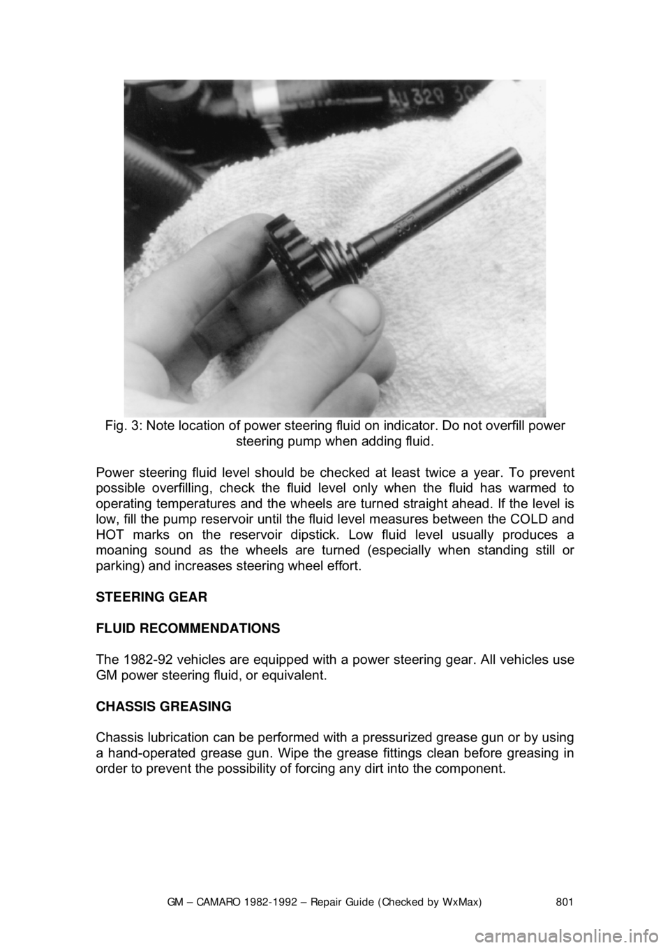
Fig. 2: Power steering pump reservoir cap with fluid level indicator attached
Page 801 of 875

GM – CAMARO 1982-1992 – Repair Guide (Checked by WxMax) 801
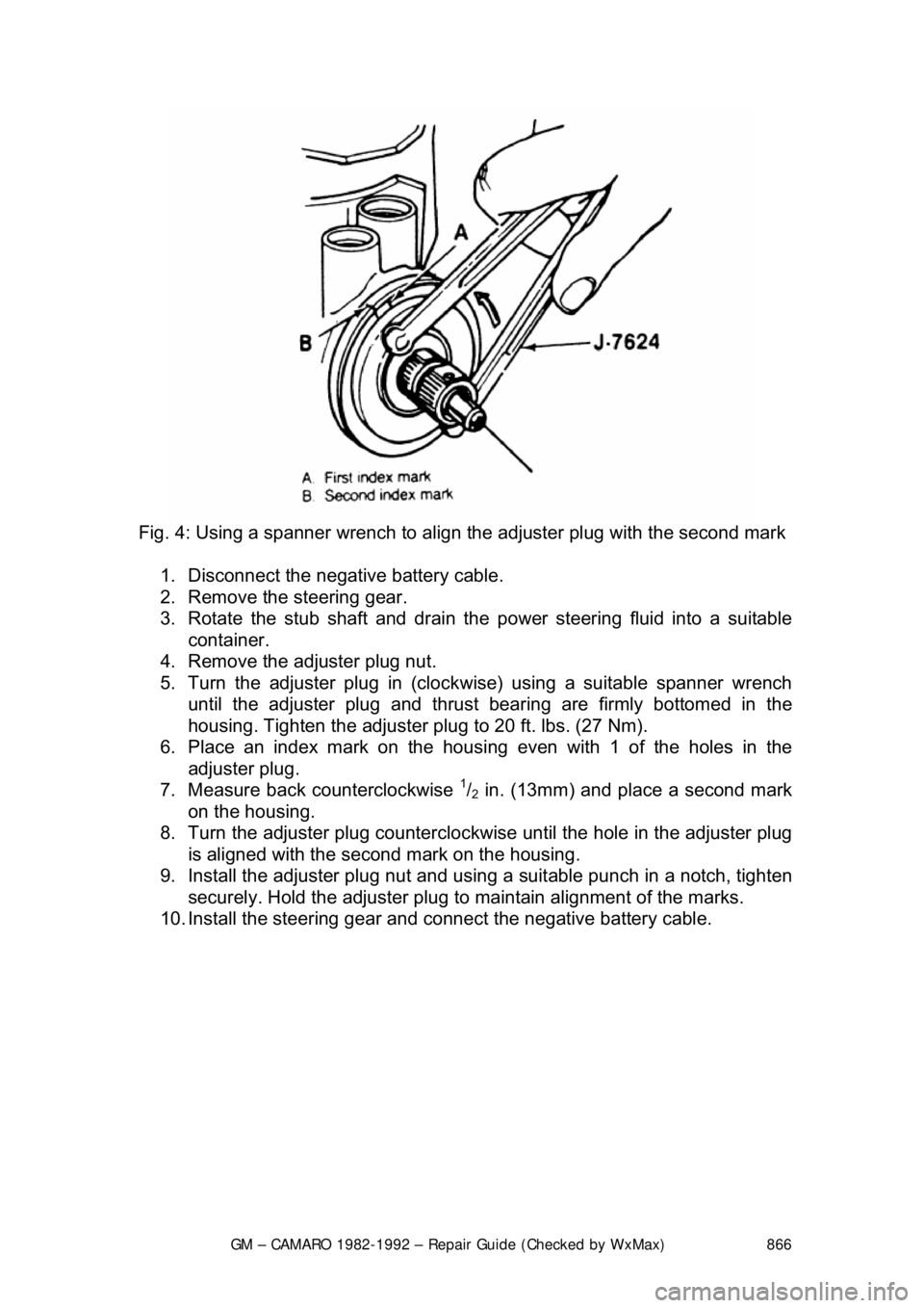
Fig. 3: Note location of power steering fluid on indicator. Do not overfill power
steering pump when adding fluid.
Power steering fluid level s hould be checked at least twice a year. To prevent
possible overfilling, check the fluid le vel only when the fluid has warmed to
operating temperatures and the wheels are turned straight ahead. If the level is
low, fill the pump reservoir until the flui d level measures between the COLD and
HOT marks on the reservoir dipstick. Low fluid level usually produces a
moaning sound as the wheels are turned (especially when standing still or
parking) and increases st eering wheel effort.
STEERING GEAR
FLUID RECOMMENDATIONS
The 1982-92 vehicles are equipped with a pow er steering gear. All vehicles use
GM power steering fluid, or equivalent.
CHASSIS GREASING
Chassis lubrication can be performed with a pressurized grease gun or by using
a hand-operated grease gun. Wipe the grease fittings clean before greasing in
order to prevent the possibility of fo rcing any dirt into the component.
Page 866 of 875

GM – CAMARO 1982-1992 – Repair Guide (Checked by WxMax) 866
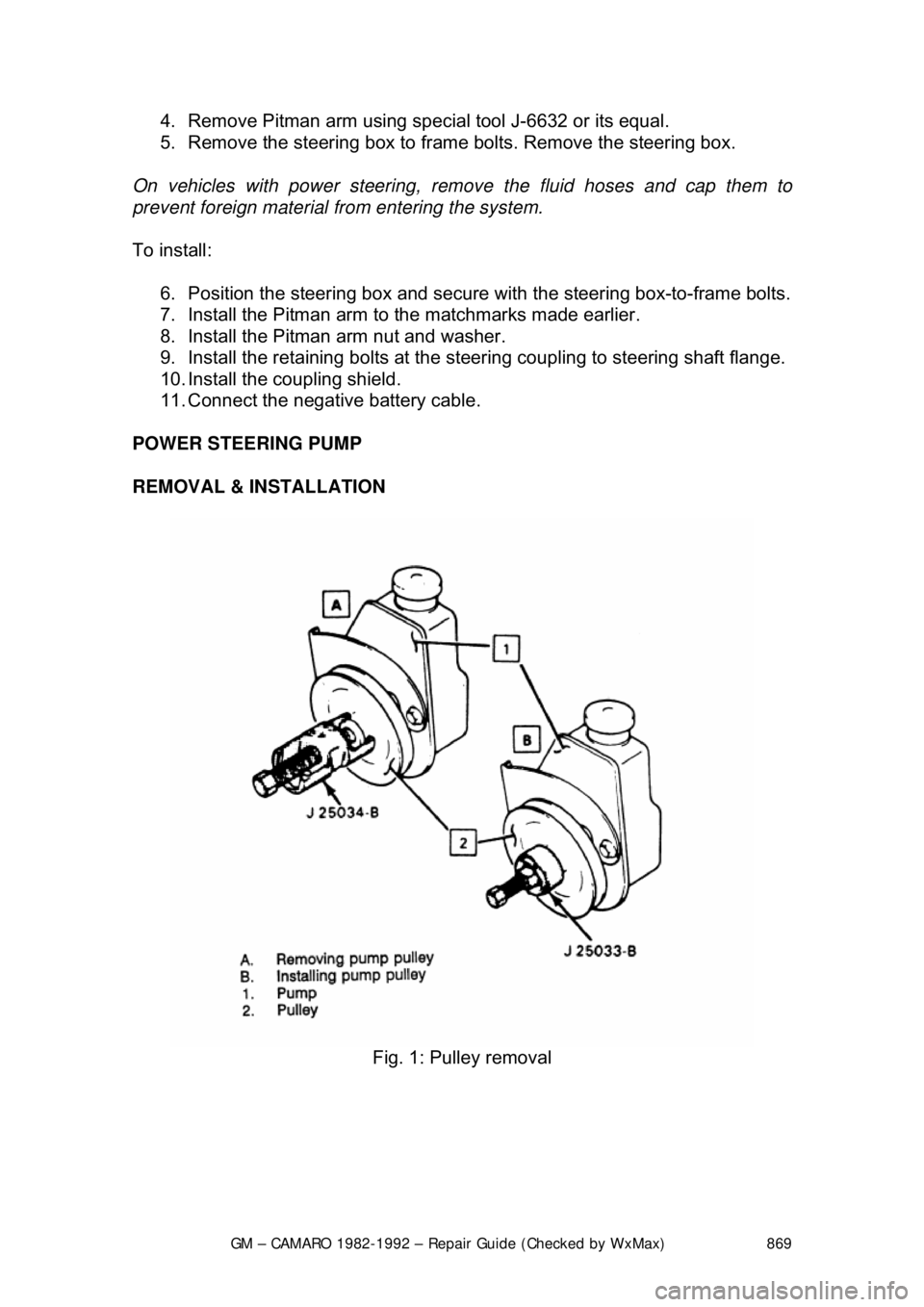
Fig. 4: Using a spanner wrench to align the adjuster plug with the second mark
1. Disconnect the negative battery cable.
2. Remove the steering gear.
3. Rotate the stub shaft and drain the power steering fluid into a suitable
container.
4. Remove the adjuster plug nut.
5. Turn the adjuster plug in (clock wise) using a suitable spanner wrench
until the adjuster plug and thrust bearing are firmly bottomed in the
housing. Tighten the adjuster plug to 20 ft. lbs. (27 Nm).
6. Place an index mark on the housi ng even with 1 of the holes in the
adjuster plug.
7. Measure back counterclockwise
1/2 in. (13mm) and place a second mark
on the housing.
8. Turn the adjuster plug counterclock wise until the hole in the adjuster plug
is aligned with the second mark on the housing.
9. Install the adjuster plug nut and using a suitable punch in a notch, tighten
securely. Hold the adjuster plug to ma intain alignment of the marks.
10. Install the steering gear and c onnect the negative battery cable.
Page 868 of 875

GM – CAMARO 1982-1992 – Repair Guide (Checked by WxMax) 868
3. Rotate the stub shaft and drain the
power steering fluid into a suitable
container.
4. Turn the Pitman shaft adjuster screw counterclockwise until fully
extended, then turn back 1 full turn.
5. Rotate the stub shaft from stop-to -stop and count the number of turns.
6. Starting at either stop, turn the stub shaft back half the total number of
turns. This is the "Center" posit ion of the gear. When the gear is
centered, the flat on the stub sha ft should face upward and be parallel
with the side cover, and the master spline on the Pitman shaft should be\
in line with the adjuster screw.
7. Rotate the stub shaft 45 degrees each side of the center using a suitable
torque wrench with the hand le in the vertical position. Record the worm
bearing preload measured on or near the center gear position.
8. Adjust the over-center drag torque by loosening the adjuster locknut and
turning the Pitman shaft adjuster screw clockwise until the correct drag
torque is obtained: Add 6-10 inch lbs. (0.7-1.1 Nm) of torque to the
previously measured wo rm bearing preload torque. Tighten the adjuster
locknut to 20 ft. lbs. (27 Nm). Prev ent the adjuster screw from turning
while tightening the adju ster screw locknut.
9. Install the steering gear and c onnect the negative battery cable.
REMOVAL & INSTALLATION
Fig. 7: Steering gear removal
1. Disconnect the negative battery cabl e. Remove the coupling shield.
2. Remove the retaining bolts at t he steering coupling to steering shaft
flange.
3. Remove the Pitman arm nut and wa sher. Mark the relation of the arm
position to the shaft.
Page 869 of 875

GM – CAMARO 1982-1992 – Repair Guide (Checked by WxMax) 869
4. Remove Pitman arm using spec
ial tool J-6632 or its equal.
5. Remove the steering box to fram e bolts. Remove the steering box.
On vehicles with power steering, remo ve the fluid hoses and cap them to
prevent foreign material from entering the system.
To install:
6. Position the steering box and secure with the steering box-to-frame bolts.
7. Install the Pitman arm to the matchmarks made earlier.
8. Install the Pitman arm nut and washer.
9. Install the retaining bolts at the st eering coupling to steering shaft flange.
10. Install the coupling shield.
11. Connect the negative battery cable.
POWER STEERING PUMP
REMOVAL & INSTALLATION
Fig. 1: Pulley removal