1982 CHEVROLET CAMARO cruise control
[x] Cancel search: cruise controlPage 168 of 875

GM – CAMARO 1982-1992 – Repair Guide (Checked by WxMax) 168
CRUISE CONTROL
CONTROL SWITCHES
REMOVAL & INSTALLATION
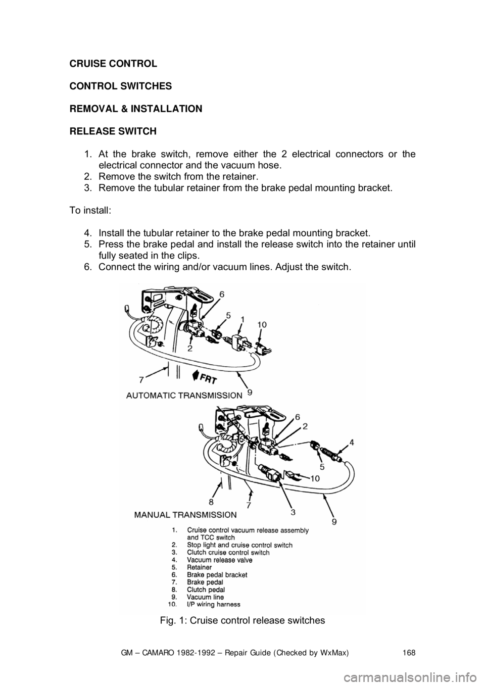
RELEASE
SWITCH
1. At the brake switch, remove either the 2 electrical connectors or the
electrical connector and the vacuum hose.
2. Remove the switch from the retainer.
3. Remove the tubular retainer fr om the brake pedal mounting bracket.
To install: 4. Install the tubular retainer to the brake pedal mounting bracket.
5. Press the brake pedal and install the release switch into the retainer until
fully seated in the clips.
6. Connect the wiring and/or vac uum lines. Adjust the switch.
Fig. 1: Cruise control release switches
Page 169 of 875

GM – CAMARO 1982-1992 – Repair Guide (Checked by WxMax) 169
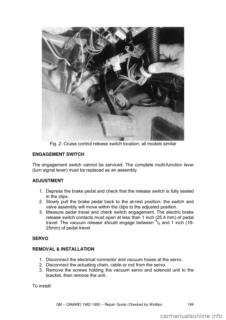
Fig. 2: Cruise control release sw itch location; all models similar
ENGAGEMENT SWITCH
The engagement switch cannot be serviced . The complete multi-function lever
(turn signal lever) must be replaced as an assembly.
ADJUSTMENT
1. Depress the brake pedal and check that the release switch is fully seated
in the clips.
2. Slowly pull the brake pedal back to the at-rest position; the switch and
valve assembly will move within the clips to the adjusted position.
3. Measure pedal travel and check s witch engagement. The electric brake
release switch contacts must open at less than 1 inch (25.4 mm) of pedal
travel. The vacuum release should engage between
5/8 and 1 inch (16-
25mm) of pedal travel.
SERVO
REMOVAL & INSTALLATION 1. Disconnect the electrical connecto r and vacuum hoses at the servo.
2. Disconnect the actuating chain, cable or rod from the servo.
3. Remove the screws holding the vac uum servo and solenoid unit to the
bracket, then remove the unit.
To install:
Page 175 of 875

GM – CAMARO 1982-1992 – Repair Guide (Checked by WxMax) 175
CHAIN AND CABLE
CHAIN AT THROTTLE
1. Check for proper installation of cabl e assembly. Inspect the throttle; it
must be in the idle position.
2. Install the chain in the swivel so that the slack does not exceed
1/2 the
diameter of the ball stud.
3. Install the retainer on the swivel and make sure the throttle has not
moved from idle.
CHAIN AT SERVO 1. Check for proper installation of cabl e assembly. Inspect the throttle; it
must be in the idle position.
2. Install the cable on the third link of the chain; adjust the jam nuts of the
servo until there is no noticeab le slack in the chain.
3. Tighten the jam nuts and check that the throttle has not moved out of the
idle position.
MODULE
REMOVAL & INSTALLATION
1984-1992 MODELS
The module is mounted next to the heater and A/C duct on most models, but is
integral with the ECM on certain late-model engines.
1. Disconnect the negative battery cable.
2. Remove the right side sound insulator.
3. Remove the module attaching screws and remove the module.
4. Disconnect the electrical connector.
To install: 5. Connect the electrical connector.
6. Install the cruise control module and the attaching screws.
7. Install the right side sound insulator.
8. Connect the negative battery cable.
Page 176 of 875

GM – CAMARO 1982-1992 – Repair Guide (Checked by WxMax) 176
Fig. 1: mounting of cruise control module
MULTI-FUNCTION LEVER
REMOVAL & INSTALLATION 1. Disconnect the negative battery terminal.
2. Disconnect cruise control switch connector at the base of steering
column. It may be necessary to re move an under dash panel or trim
piece for access.
3. Make sure the lever is in the OFF position.
4. Pull the lever straight out of the retaining clip within the steering column.
5. Attach mechanic's wire or simi lar to the connector; gently pull the
harness through the column, leaving the pull wire in place.
To install: 6. Attach the mechanic's wire to the connector. Gently pull the harness into
place, checking that the harness is completely clear of any moving or
movable components such as tilt column, telescoping column, brake
pedal linkage, etc.
7. Position the lever and push it squarely into the re tainer until it snaps in
place.
8. Remove the mechanics' wire and connect the cruise control harness
connector.
9. Reinstall any panels or insulation which were removed for access.
10. Connect the negative battery terminal.
Page 199 of 875

GM – CAMARO 1982-1992 – Repair Guide (Checked by WxMax) 199
Federal law requires that the
odometer in any replacement
speedometer/odometer must r egister the same mileage as that registered on
the removed speedometer/odometer. Service replacement
speedometer/odometers and odometer modul es with the mileage preset to
actual vehicle mileage are available through the dealer. In nearly all cases, the
mileage continues to accumu late in the odometer memory even if the odometer
does not display mileage. Th is mileage can usually be verified by the dealer.
Contact the dealer for instructi ons to receive a replacement
speedometer/odometer with pres et mileage. If the actual vehicle mileage cannot
be verified, the dealer will supply a spe edometer/odometer with a display set to
zero miles. In addition, an odometer mileage sticker is supplied with the
replacement odometer. The sticker must display the estimated vehicle mileage
and is to be affixed to the driver's door.
REMOVAL & INSTALLATION 1. The gauges can be removed from the cluster assembly by: a. Removing the cluster lens.
b. Removing the printed circuit board from the back of the cluster.
c. Removing the gauge attaching screws.
2. Installation is the reverse of removal.
SPEEDOMETER CABLE
REMOVAL & INSTALLATION 1. Disconnect the negative batte ry cable at the battery.
2. On models without cruise control, disconnect the speedometer cable
strap at the power brake booster. On models with cruise control,
disconnect the speedometer cable at the cruise control transducer.
3. Remove the instrument cluster trim plate.
4. Remove the instrument cluster a ttaching screws and pull the cluster out
far enough to gain access to the r ear of the speedometer head.
5. Reach beneath the c able connection at the speedometer head, push in
on the cable retaining spring, and disconnect the cable from the
speedometer.
6. Slide the old cable ou t of the speedometer cable casing. If the cable is
broken, remove the cable from both ends of the casing. Using a short
piece of the old cable to fit t he speedometer connection, turn the
speedometer to increase the speed i ndicated on the dial and check for
any binding during rotation. If binding is noted, the speedometer must be
removed for repair or replacement. Check the entire cable casing for
extreme bends, chafing, breaks, et c., and replace if necessary.
To install: 7. Wipe the cable clean us ing a lint free cloth.
8. If the old casing is to be reused, flush the casing with petroleum spirits
and blow dry with compressed air.
Page 200 of 875

GM – CAMARO 1982-1992 – Repair Guide (Checked by WxMax) 200
9. Lubricate the speedometer cable
with an appropriate lubricant, being
sure to cover the lower thirds of the cable.
10. Insert the cable into the casi ng, then connect the cable and casing
assembly to the speedometer.
11. Install the instrument cluster, then install the cluster attaching screws.
12. Install the instrument cluster trim plate.
13. On models without cruise control, connect the speedometer cable strap
at the power brake booste r. On models with cruise control, connect the
speedometer cable at the cr uise control transducer.
14. Connect the negative battery cable at the battery.
WIPER SWITCH
REMOVAL & INSTALLATION
The wiper switch is part of the multi-function lever, located on the steering
wheel column.
1. Disconnect the electrical connector of the multi-function lever, located
under the instrument panel.
2. Remove the protective cover from the wire.
3. Grasp the lever firmly, twist and pull (the tang on the lever must align
with the socket) the lever straight out.
4. Pull the wire through the steering column.
To install: 5. Slide a music wire tool through the steering column and connect the
lever wire to the tool wire; pull t he wire through the steering column.
6. Push the control lever into the sp ring loaded socket (be sure to align the
tang).
7. Install the protective cover to the wire.
8. Connect the electrical connector of the multi-function lever.
HEADLIGHT SWITCH
REMOVAL & INSTALLATION 1. Disconnect the negative batte ry cable at the battery.
2. Remove the four screws from insi de the defroster duct (instrument panel
pad securing screws).
3. Remove the screws which are under the lip of the instrument panel pad.
4. Remove the instrument panel pad.
5. On models equipped with air condition ing, remove the instrument panel
cluster bezel and the cluster.
6. Remove the radio speaker bracket.
7. Pull the headlamp switch knob to the ON position, depress the locking
button for the knob and shaft (locat ed on the switch), and remove the
knob and shaft.
8. Remove the switch bezel (retainer).
Page 296 of 875

GM – CAMARO 1982-1992 – Repair Guide (Checked by WxMax) 296
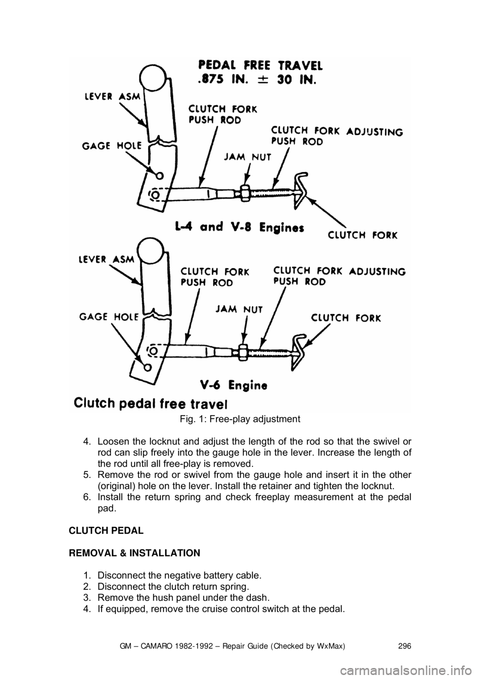
Fig. 1: Free-play adjustment
4. Loosen the locknut and adjust the length of the rod so that the swivel or
rod can slip freely into the gauge hole in the lever. Increase the length of
the rod until all free-play is removed.
5. Remove the rod or swivel from the gauge hole and insert it in the other
(original) hole on the lever. Install the retainer and tighten the loc\
knut.
6. Install the return spring and che ck freeplay measurement at the pedal
pad.
CLUTCH PEDAL
REMOVAL & INSTALLATION 1. Disconnect the negative battery cable.
2. Disconnect the clutch return spring.
3. Remove the hush panel under the dash.
4. If equipped, remove the cruise control switch at the pedal.
Page 364 of 875

GM – CAMARO 1982-1992 – Repair Guide (Checked by WxMax) 364
5. Drain the radiator and remove t
he radiator hoses. Disconnect the heater
hoses and the transmission cooler lines.
6. Remove the upper half of the radi ator shroud, if equipped with a manual
transmission. Remove the radiator and fan shroud assembly, if equipped
with an automatic transmission.
7. Disconnect the throttle linkage, includi ng the cruise control detent cable.
8. Remove the air conditioning compressor and lay aside.
Do not disconnect the air conditioning lines.
9. Disconnect the power steering pump and drain the fluid into a suitable
container. Remove the vacuum brake booster line.
10. Remove the distributor cap and spark plug wires.
11. Disconnect the engine electrical connection at the bulkhead connection
and disconnect any necessary vacuum hoses.
12. Working inside the vehicle, re move the right-hand hush panel and
disconnect the ECM harness at the EC M. Raise and safely support the
vehicle. Remove the right fenderwell splash shield and feed the harness
through the fenderwell.
13. Disconnect the exhaust pipes at the exhaust manifolds and remove
exhaust system from the vehicle.
14. Remove the flywheel cover and remo ve the converter bolts, if equipped
with automatic transmission.
15. Disconnect the transmission an d starter wire connections.
16. Remove the bellhousing and t he motor mount through-bolts.
17. Disconnect the clutch fork return spring, if equipped with a manual
transmission. Lower the vehicle.
18. Relieve the fuel system pressu re. Disconnect the fuel lines.
19. Support the transmission with a suit able jack. Attach an engine lifting
device.
20. Remove the engine assembly.
To install: 21. Position the engine assembly in the vehicle.
22. Attach the motor mount to engine br ackets and lower the engine in place.
Remove the engine lifting device and the transmission jack.
23. Raise and support the vehicle safely.
24. Install the motor mount through-bolts and tighten the nuts to specification. Install t he bellhousing bolts and tight en to 35 ft. lbs. (47
Nm).
25. On vehicles with automatic transmissi on, install the converter to flywheel
attaching bolts to 46 ft. lbs. (63 Nm).
26. Install the flywheel splash shield and tighten to 89 inch lbs. (10 Nm).
Install the clutch return spring, if equipped with manual transmission.
27. Connect the starter wires and the fuel lines.
28. Install the exhaust system.
29. Lower the vehicle.
30. Install the power steering pump and the air conditioning compressor.