1980 CHEVROLET CITATION low oil pressure
[x] Cancel search: low oil pressurePage 8 of 95
Downloaded from www.Manualslib.com manuals search engine SEAT CONTROLS
ADJUSTMENT OF SEAT POSITION
Manually Operated Front Seats
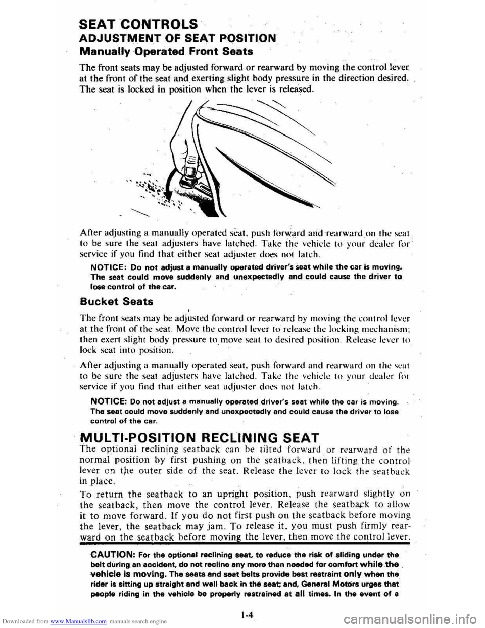
The front seats may be adjusted forward or rearward by moving the control lever
at the front of the seat and exerting slight body pressure in the direction desired.
The seat
is locked in position when the lever is released.
After adjusting a manually operated seat. push forward and rearwardon the scal
to be sure the seat adjusters have latched. Take the vehicle 10 Y(lur dealer for
service if you find that either seat adjuster does IIi)! lakh.
NOTICE: Do not adjust a manually operated driver's seat while the car is moving. The seat could move suddenly and unexpectedly and could cause the driver to lose control of thecaf.
Bucket Seats , The front seats may be adjusted forward or rearward by moving the control lever at the front of the seat. Move the control lever to release the locking mechanism;
then exert slight body pressure to. move seat to desired position. Release lever to lock seat into position.
After adjusting a manually operated seat. push forward and rearward Oil the scat to be sure the seat adjusters have latched. Take the vehicle to your dealer fo!
service if you find that either seat adjuster docs not latch.
NOTICE: Do not adjust a manually operated driver's seat while the car is moving. The seat could move suddenly and unexpectedly and could cause the driver to lose control of the car.
MULTI-POSITION RECLINING SEAT The optional reclining seat back can be tilted forward or rearward of the
normal position by first pushing on the seatback. then lifting the control
lever O!l the outer side of the seat. Release the lever to lock the seat back
in place.
To return the seatback to an upright position. push rearward slightly on
the seatback, then move the control lever. Release the seatba.:k to allow
it to move forward. If you do not first push on the seat back before moving
the lever, the seat back may jam. To release it. you must push firmly rear
ward on the seat back before moving the lever, then move the control lever.
CAUTION: For the optional reclining seat. to reduce the risk of sliding under the belt during an accident, do not recline any more than needed for comfort while the vehicle is moving. The seats and seat belts provide best restraint only when the rider is Sitting up straight and well back in the seat and, General .Motors urges that people riding in the vahicle be properly restrained at all times. In the event of a
1-4
Page 16 of 95
Downloaded from www.Manualslib.com manuals search engine Tir,s
When lowing trailers using a dead-weight hitch, inflate tires to the "Cold Tire
Pressure" for ·'Max . Load" show n on the Tire Placard on the left front door.
The allowable passenger and cargo load for this car,
also sh o wn on· the Tire
Placard, is reduced by the trailer tongue weight whenever the trailer is attached
t o the car.
Maintenance
More frequen.t servic e is requi red when using your car to pull a trailer. See Section
A of the Maint enance Schedule folder for Tran saxle Fluid and Engine Oil chang e
requirement~ for traitering.
Now and then. check that all trailer hitch bolts an d nuts are tight. Also see
"the Maintenance Schedule rol_def, and the Index in this manual , for important facts
o n
belts, coo ling system care and brake adjustment.
Break-In Schedule
See the new car break~in instru ctions in this manual. Also,. we recommend you
drive your new car for
500 mil es (800 kilometer s) before trailer tOwing. At the
" end
of this 500 mile (800 kilome te r) break-in period, avoid speeds over 50 mph (80 km/h) and full throttl e start s during the first 500 miles (800 kilometers) of
trailer towing.
If a new engine or transaxle is ins talled in you r car, observe the
same
care.
CAUTIONS:
Brakes -To help avoid personal injury due to poor braking action:
• Trailer brakes of adequate size are required on trailer s over 450 kilograms
(1,000 pounds) loaded weight.
• If you use trailer brakes with this car, follow the installation and balan ce
instructi ons
of the trailer brake maker.
• Do nol lap into the car's brake system if the trailer brake system uses more than 0.3 cubic centimeter (0.02 cubic inch) of nuid from the ca r's master
cylinder. In this case, the car's brake fluid capacity will not be enough to
operate
both the car and trailer brakes under all kind s, of use.
• All brak e fluid parts must be able to stand 20 685 kPa (3,000 psi). The brake
fluid tap must be made al th e upper rear master cylinder port. Copper tubing is subject to fatigue failure and must no t be used.
• Before going down a sleep or long grade , reduce speed and shift the tran saxle
into a lower gear to control your car's speed.
Try not to hold the brake pedal
down too long or too often. This could cause the brake s to get hot and not
work
as well.
Hitches -To help avoid personal injury due to sway caused by such things as
c rosswind
s, big trucks passing or road roughn ess, or due to sepa ration of the
trailer :
• Keep the trailer tongue load at 10% of the loaded trailer weight for
dead-w eight hitches. Tongue loads can be adjusted by proper distribution of the load in the trailer. This can be checked by weighing separately the loaded
trailer and then the tongue,
• When you remove a frailer hitch, be sure to seal any mountin g h'oles in the
body . This will help prevent entry of exhaust fumes, dirt or water. (See
"Engine Exhaust Gas Caution (Carbon Monoxide) " at the beginning of "Starting and Operating," Section 2 of this manual.)
1-12
Page 34 of 95
Downloaded from www.Manualslib.com manuals search engine Oil/Choke Indicator Light
This light will c0!TIe on to provide a "bulb check", w hen the igni tion is turned on, but sh Qu19 go out after the _ engine is started. If tight fails to
come on wit h ignitio~ turned on, it could indicate a burned out bulb , a
defective electric choke hea ter circuit (on L4 and V6 engines), or a blown
instrument lamp fuse. Have system repaired if light does not come on d min g ch eck .
Occa sionally. this light may flicker momentarily while the engine is running. Should this occur, CHECK EN GINE OIL LEVEL as outlined in Section 5,
"Checking Oil Level." If the light comes on continuously, pull over toa safe place and STOP THE ENGINE until the source of trouble can be loca ted and corrected.
The source of tro uble could be any of the following:
• Loss of engine oil press ure (cbec k eng ine oil level).
• Blown choke heater fuse.
• Loss. of electric choke heate r voltage.
Continuing to run the engine with an illuminated oil pressure light can cause
serious engine damage or unusu ally high exhaust system temperature which can
r esult in serio us damage to the
vehicle. Pull over to a safe place and STOP THE
VEHICLE IMMEDIATELY AND SHUT OFF ENGINE. If the light flashe s
momentarily , ch
eck engine oil leve l as outlined in Sectio n 5 of thi s manu al
Choke Warning Indicator Light
On some vehicles equipped with the optiona l oil pressure gage, an amber choke
warning indicator light replaces the red oil pressure indicator light in the
instrument cluste
r. If this light comes on, indicating loss of electric choke heater
volta
ge, have your authoriz ed Dea ler .locate and correct th e tro uble as soon as
p ossib l
e.
Generator Indicator Light The red ligh t GEN will go on when the ignition key is in the "run" _posit ion, but
before the engi ne
is started. After the engine s tarts, the light should 'go out and
r e m ain out .
If th e light remains on when en gine is running , have your Authorized
D eale r loca te and correct the troubl e as soo n as possibl
e.
Engine Temperature .Indicator Light This indicator light is provided in th e instrument cluster to quickly warn of an
overh eated en gi ne. With the igniti on switch in the START position, the red
TEMP indicator (hot light) will light to let you know that it is operati ng prope rly.
When the engi ne is started ;-th e re d light will go out imm ediate ly. It wilUight up
a t n o other time unleSS for some reason the engine reaches a dangerously high ope ra tin g temperature . 1f the light comes on during extreme driving condition s,
such as an exte nded idle, see "E ngine Cooling
System" on page 3-3. Glance at
th e instrument cluster frequently as you drive to see if this
ligh t is on.
Brake System Warning Light
The regular braking system is a dual system designed so that one part will provide
some braking action if there is a loss of hydraulic pressure in the other part of
the system. The system has a "Brake" warning light loca ted in the instrum ent
pane\.
• To serve as a reminder , the "Bra ke" lig ht is designed to come on while the
park ing brake is se t and the ignition key
is on.
• The light is also designed to come on briefly during engine starting so you
can chec k that the bulb is okay.
• Have the system repaired if the light does not come on during engine starting
o r when the parking brake
is set. 2-17
Page 36 of 95
Downloaded from www.Manualslib.com manuals search engine Engine Temperature Gage
This gage indicat~cCX?lant temperature which will vary with air temperature and
operating condition~, The ignition must be on for accurate readings. Hard driving
or prolonged idling In very hot weather will cause the pointer to move beyond the center of the band; Should pointer move to the Red Zone, see "Engine Cooling
System" on page 3-3.
Oil Pressure Gage
The oil pressure gage indicates the pn;ssure at which oil is being delivered 10 the various parts of the engine requiring lubrication. Pressures registered by the gage
I11.!lY vary according to outside air temperatures or weight of oil being used. Oil
pressure of a cold engine ~ing operated at a given speed will be somewhat higher
than when the engine is at normal operating temperature at the same speed .
. Prolonged high speed operation on a hot day at the given speed will result in somewhat lower oil pressure readings. Readings of 30 to 40 psi (205 to 275 kPa)
mny
be considered normal during moderate road speeds of 35 to 40 mph (55 to
60 km/h) \\lith the engine at proper operating temperature. Gage readings which
are
consistently high or Im\l under these conditions may indicate lubrication system
When the engine is operating, the voltmeter indicates the electrical system voltage.
During minimum electrical load, the pointer will read to the right of the center.
As the electrical load is increased,
or in stop-and-go driving, the pointer will rotate
to the left. A meter reading continuously in
the left or right red zone indicates
an electrical system
failure .. Cause of the failure should be determined and corrected~
Light Switch
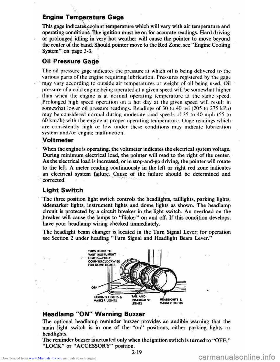
The three position light switch controls the headlights, taillights, parking lights,
sidemarker lights, instrument lights and dome lights as shown. The headlamp
circuit is protected by a circuit breaker in
the light switch. An overload on the
breaker will cause the lamps to "flicker" on and off. If this condition develops,
have your headlamp wiring checked immediately.
The headlight beam changer is located. in the
Turn Signal Lever; for operation
see Section 2 under heading "Tum Signal and Headlight Beam Lever."
TUIN KNOt TO VAr:t'INSTRUMENT lIGHTS_'UtLy COUNTERClOCKWISE RlR DOME
0"
MAltlCfIt LIGHTS , INSTRUMENT LIGHTS
Headlamp "ON" Warning Buzzer
The optional headlamp reminder buzzer provides an audible warning that the
main light switch is in one
of the "on" positions, either parking lights or
headlights.
The reminder buzzer
is actuated only when the ignition switch is turned to "OFF," "LOCK" or "ACCESSORY" position.
2-19
Page 53 of 95
Downloaded from www.Manualslib.com manuals search engine JACKING
CAUTION
To help avoid personal injury:
• Follow all jackin g and stowag e instructions.
• Use jack only fo r liftin g this venicle du -rin g wheel c h a ng e.
• Nev er ge t ben eath th e vehiCle, start or run en g in e while vehicle is supported b y jac k.
• Always securely res tow spare tire (o r flat tire ) an d all jackin g equipment.
Wheel Nut Torque
CAUTION: As soon as possible after Installing 8 wheel-and at the intervals shown on the chart-in the Maintenance Schedule foldet-han 8 m.chanic tighten whe&l nuta with II torque wrench to the specifications shown in "SpeCifications ," Section 7 of this manual. Wheel nuts should be tightened alternately and evenly to the correct torque. Never us. oil or grease on studs or nuts. Improperly tightened wheel nuts could eventually allow the wheel to come off while the vehicle is moving, possibty causing loss of control.IAlso see the Caution in "Service and Maintenance," Seetion 5 of this manual regarding the danger of mixing metric and customary fasteners.)
Stowage of Tire and Jack
CAUTION:·AlwaYs MOurely restow the spare tire assembty (or flat tire). all jacking equipment. and the cover, using the means provided. When driving the car with the compact spare installed and the reer seat folded down, stow the wheel cover flat on the rear floor behind the-right front seat. When the rear seat is up (or If It does not fold), stow the wheel cover in the trunk area. This will help keep such things from being thrown about and injuring peopla In the car in an accident.
Compact Spare
The compa ct sp are is des ig ned to save space in yo ur trunk, and its lighler weig ht
m ak es
it easi er to in stall if a flat tire occurs. The light~r weig ht als o helps improve fuel eco no my.
If you have a flat tire, follow the jack ing in struction s in this manual while keeping
t h ese point s in min d:
• Chec k inflati on press ure as soo n as practical after in sta llin g the s pa re ( use of a pocke t type: high pressure inflatio n gage is adv ised) and adjust to 415
k Pa (60 psi). The tire pressur e sh o uld be checked at least monthl y and kept at 415 kPa (60 ps i) while the tire is s tored.
• Co ntinuou s use at spe eds over 50 mph (80 km/h) is not re c omme nded .
NOTICE: Because this tire is amaUer than the standar d tire, vehicle ground clearance is reduced, Avoid driving over obstacles, and do not take your car U,rough an automatic car wash whila the spare is installed. The car may get caught possibly resulting in property damage.
• A trea d life of up to 3,000 mil es (4 800 kilomet ers) ca n b e expe cted, depe nding
on roa d condi tions and you r
driv ing habits . T o co nserve tire t read life. return the spar e to the sto rage area as soo n as the sta nd ard tir e ca n be repa ir ed -or
r
epl ac ed .
• Beca use the co mpac t spare was spec ifica lly designe d for your car, it s hould
no t be used on any other vehicle.
3-6
Page 56 of 95
Downloaded from www.Manualslib.com manuals search engine 4. If a ring forms after spot cleaning, dean the entire area IMMEDIATELY.
5. Follow specific instructions on cleaner labels.
CLEANING GENERAL SOILAGE OR WATER SPOTS FROM
FABRIC-TYPE TRIM WITH FOAM-TYPE CLEANER
GM Multi~Purpose Powdered Cleaner is excellent for this type of cleaning, and
for cleaning panel sections where
small cleaning rings may be left from spot
cleaning .
• Vacuum'~rea thoroughly to remove loose dirt.
• AL WAYS clean a fuJI trim assembly or complete trim section. Mask
surrounding trim along stitch
or well Hnes.
• Mi x Multi-Purpose Powdered Cleaner in -strict accordance with direction s
on label of container. Mix in proportion for smaller quantities.
• USE SUDS ONLY ON A CLEAN SPONGE OR SOFT BRISTLE BRUSH. DO NOT SATURATE FABRIC OR RUB HARSHLY WITH BRUSH.
•
IMMEDIATELY AFTER CLEANING, WIPE OFF EXCESS CLEANER WITH SLIGHTLY DAMP ABSORBENT TOWEL OR CLOTH.
IMPORTANT' -IMMEDIATELY AFTER WIPING, FORCE-DRY
FABRIC WITH AIR HOSE, HEAT DRYER OR HEAT LAMP. (Use
ca ution with-beat dryer
or lamp to, help prev~nt damage to fabri c.)
• When trim materials with a sheen or luster finish are dry, wipe fabric lightly with a soft. dry,c1ean cloth to restore its sheen or luster.
SPOT CLEANING FABRIC-TYPE TRIM WITH SOLVENT
TYPE CLEANER
Before trying to remove -a spot or stain from fabric , detennine as accurately as
y o u ca n wha t kind and how old the spot
or stain is. Some spots or stains can be removed with water or mild ~p solution (see "Removal of Specific Stains ").
Spots or stains should always be removed as soon as possi ble.
Some tyPes of stains or soilage, such as lipstick, . ink s and gre ase"are very difficult
(sometimes impossible) to completely reIilove~ When cleaning this type ·of stain or soilage ,' be,: sure not to en)arg e,:the soiled area. .
GM Fabric Cleaner (Solvent Type) is exceHent for spot c1ea,ning grease, oil, or
fat stains .
• Gently scrape -exceSs stain otT trim material with a clean . DULL knife or .
sc raper .
USE VERY LITTLE CLEANER, light pressure, and clean cloths
(preferably c heesecloth) . Cleaning , shquld be from outside of stain "FEATHERING" towards the center;-Keep changing to a clean section of
cloth .
• Wben stain is cleaned from ,fabric,immediately dry area with an air hose.
heat dryer, or heat lamp 'to help ,prevent a cleaning ring. (Use caution with
heat dryer or lamp to prevent damage to fabric) .
• If a ring forms . immediately repeat the deaning operation over a slightly
larger area with emphasi s on "FEA THERINO" toward s its center. If ring
still remains, mask ofT surrounding trim-sections and clean entire affected area
with
GM MUlti-Purpose Powdered Cleaner (as described under -"Cleaning
' General Soilage or Water Spots with -Foam Type Cleaner").
4-2
Page 67 of 95
Downloaded from www.Manualslib.com manuals search engine remOve tlie cap on the coolant ~ecove~y tank : Add to the tank enough of a 50 150 . mixture of w ater and a g ood quality eth)dene glycol antifreez e to bring the level
up to the .
proper mark. Put the cap bac k on the tank .
Certain
conditi ons; "Such as air trapped in the syste m, may affe ct the coolant level
in
the radiator. You sho uld ch ec k the co olant ·Ievel ·in the radiator while you
change the engine oil and the e ng ine is col d. Follow steps I , 8, 9 and 10 und er
"Coola nt Rep lacement" for the correct way to rt!move the radiator cap .an d add
. coolant.
If you have to add coola nt more than f our tim es a yea r (ei ther to th e recov ery
tank
or to the radiat or). see your dealer. for a. c oo lin g system chec k.
NOTICE: If the proper quality antifreeze is used, there is no .nee~ to add extra inhibltOf"s or additives which claim to improve the svstem .. They may be harmful to the proper operation. I)f the system.
Cooling System Service
The cooling syste m should be serviced at the intervals specifi ed inSection A of
the Maintenan ce Sch edule fold er as follows:
I. W ash the radiatqr cap .and filler neck with clean water. See step J of "Coolant
Replacement" to remove rapiator cap. .
2. C hec k the coolant level in the radiator and have it tes ted for freeze proteCtion . Add·· ethylene gly col antifreeze, if needed, to· m aintain freeze protecti on at -37'C(-34'F),
3~ Have ·the coOlin-g sys tem and radiat or cap tested fo r a press ure capacity of
105 kPa (15 psi) . If a repl acement cap is needed"Hse an AC ca'p,or an
equivalent · cap, designed fOl: coolant recovery system ·s and spe cified for your model;
4. Tighten all radiator hose clamps and heater hose clamps and inspect an hose s.
R
eplace the hose s if they are swollen, "checked" or otherwise worn .
NOTICE: Take care when tightenjng·the hose clemps at tMI radiator. Overtightening COUld. bend or collapse .the radiator fittings.
5. Clean the front. of the radiator core and air condit ioning condenser to re m ove
dirt and oth er·objects. Al so clean the auxiliary engine oil andlor transmission -fluid ' cooler if the vehicle has them.
Coolant, Replacement
At the interval s specified in Section A of the Maintenance Schedule folder, flu sh
a
nd refill the cool ing system as follows :
1. Remove the·radiat or·cap when the engin e is ·cool :
•
Turn . t he cap s lowly to the len until ·it reaches a " stop. " Do not press down while turning the cap.
• 'Wait until any rem aining press ure (indicated by a hissing sound) is
reliev ed. then press down on the cap an d continue turning it t(j the left.
CAUTION:· To help ~lVoid the danger of being ,burned, do not remove the radiator cap while the angine and radiator are still hot s.c.lding flutd and steam can be bk)wn out under pressure if the·cap is taken off.too soon.
2. Whe n the cap is re m oved, run the eng ine until the upper radiator hose is hot.
(This shows that the thermostat is open and the coola nt is flow ing through
the . system.)
5·6
•
Page 68 of 95
Downloaded from www.Manualslib.com manuals search engine 3. Stop the engine. Open the radiator drain valve to drain the coolant. (Drainage
may be speeded by removing the drain plugs in the block.)
4. Close the drain valve (install block drain plugs, if removed). Add water until
the system is filled and run the engine until the upper radiator hose is hot again.
5. Repeat steps 3 and 4 several times until the drained liquid is nearly colorless.
6. Drain the system and then close the radiator drain valve tightly. (Install block
drain plugs, if removed.)
7. Disconnect all hoses from the coolant recovery tank. Remove the tank and
pour out any fluid. Scrub and clean the inside of the tank with soap and water.
Flush it well with clean water,
then drain it. Reinstall the tank and hoses.
8. Add enough water and ethylene glycol antifreeze (meeting GM Specification
1899-M)to provide the required cooling, freezing, and corrosion protection. Use a solution that is at least 50 percent antifreeze, but no more than 70
percent antifreeze. Fill the radiator to the base of the filler neck and fill the
coolant recovery
tank to the "Full Hot" mark. Put the recovery tank cap back
on.
9. Run the engine, with the radiator cap removed, until the upper radiator hose
is hot.
10. With the engine idling, add coolant to the radiator until it reaches the bottom
of the filler neck. Install the radiator cap, making sure the arrows on the cap line up with the overflow. tube.
It is the owner's responsibility to:
• Maintain cooling system freeze protection at _37°C (_34°F) to ensure
protection against corrosion and loss of coolant from boiling. (A SO/50
mixture of water and ethylene glycol antifreeze will provide freeze protection
to ~ 37°C ore -34°P.) You should do this even if you don't expect freezing
temperatures.
• Add ethylene glycol base antifreeze that meets GM Specification 1899-M
when antifreeze
hasto be added because of coolant loss or for more protection
' against freezing at temperatures lower than _37°C (-·J4°P).
NOTICE: Do not use alcohol or methanol-base antifreeze. or plain water alone. in your vehicle at any time. They will boil at a lower pOint than that at which the hot light indicator (or temperature gage) works. and they do not provide proper protection against corrosion.
Radiator Pressure Cap
The radiator cap, a 105 kPa(15 psi) pressure type, must be installed tightly,
otherwise coolant may be lost and damage to engine may result from overheating.
Radiator pressure caps should be checked periodically for proper operation.
If
replacement is required, an AC cap is recommended.
Thermostat
The engine coolant temperature is controlled by a thermostat. It stops coolant flow
through the radiator until a preset temperature is reached. This thermostat is
installed in
the engine coolant outlet on the engine block. The same thermostat is used in both winter and summer. When a replacement is needed, AC~Delco parts
are recommended.
5-7