1980 CHEVROLET CITATION warning light
[x] Cancel search: warning lightPage 36 of 95
Downloaded from www.Manualslib.com manuals search engine Engine Temperature Gage
This gage indicat~cCX?lant temperature which will vary with air temperature and
operating condition~, The ignition must be on for accurate readings. Hard driving
or prolonged idling In very hot weather will cause the pointer to move beyond the center of the band; Should pointer move to the Red Zone, see "Engine Cooling
System" on page 3-3.
Oil Pressure Gage
The oil pressure gage indicates the pn;ssure at which oil is being delivered 10 the various parts of the engine requiring lubrication. Pressures registered by the gage
I11.!lY vary according to outside air temperatures or weight of oil being used. Oil
pressure of a cold engine ~ing operated at a given speed will be somewhat higher
than when the engine is at normal operating temperature at the same speed .
. Prolonged high speed operation on a hot day at the given speed will result in somewhat lower oil pressure readings. Readings of 30 to 40 psi (205 to 275 kPa)
mny
be considered normal during moderate road speeds of 35 to 40 mph (55 to
60 km/h) \\lith the engine at proper operating temperature. Gage readings which
are
consistently high or Im\l under these conditions may indicate lubrication system
When the engine is operating, the voltmeter indicates the electrical system voltage.
During minimum electrical load, the pointer will read to the right of the center.
As the electrical load is increased,
or in stop-and-go driving, the pointer will rotate
to the left. A meter reading continuously in
the left or right red zone indicates
an electrical system
failure .. Cause of the failure should be determined and corrected~
Light Switch
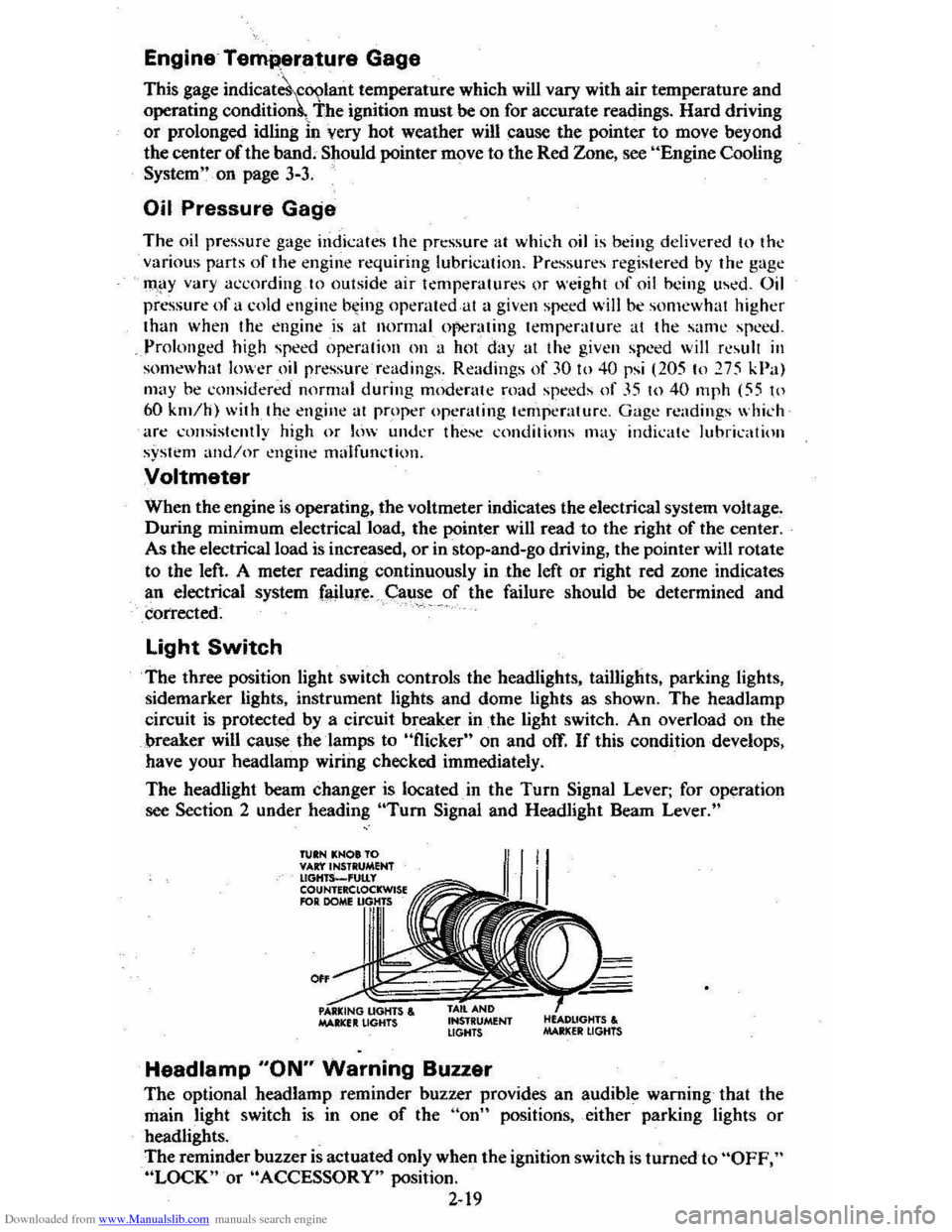
The three position light switch controls the headlights, taillights, parking lights,
sidemarker lights, instrument lights and dome lights as shown. The headlamp
circuit is protected by a circuit breaker in
the light switch. An overload on the
breaker will cause the lamps to "flicker" on and off. If this condition develops,
have your headlamp wiring checked immediately.
The headlight beam changer is located. in the
Turn Signal Lever; for operation
see Section 2 under heading "Tum Signal and Headlight Beam Lever."
TUIN KNOt TO VAr:t'INSTRUMENT lIGHTS_'UtLy COUNTERClOCKWISE RlR DOME
0"
MAltlCfIt LIGHTS , INSTRUMENT LIGHTS
Headlamp "ON" Warning Buzzer
The optional headlamp reminder buzzer provides an audible warning that the
main light switch is in one
of the "on" positions, either parking lights or
headlights.
The reminder buzzer
is actuated only when the ignition switch is turned to "OFF," "LOCK" or "ACCESSORY" position.
2-19
Page 48 of 95
Downloaded from www.Manualslib.com manuals search engine /
SECTION 3
IN CASE OF EMERGENCY
See also ",Engine Exhaust Gas Caution (Carbon Monoxide),' at the beginning of
"Starting and Operating," Section 2 of this manual.
FOUR·WAY HAZARD WARNING FLASHER
•. Use the warning flasher to warn other drivers any lime your vehicle -becomes
a traffic hazard, day or nighc.
• Avoid 'stopping on the roadway ,if possible.
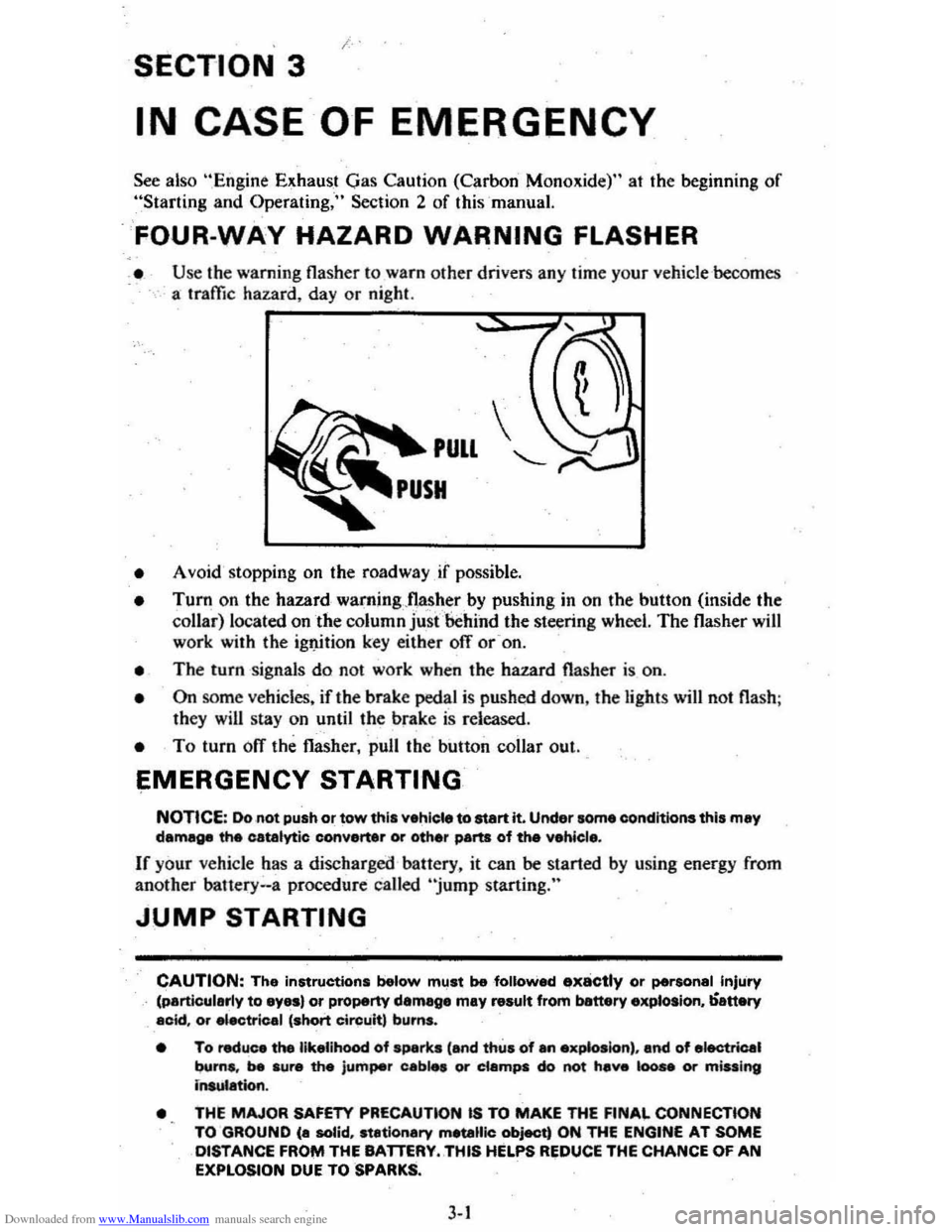
• Turn on the hazard waming"nas~,er by pushing in on the button (inside the collar) located on the column just 'behind the steering wheel. The flasher will work with the ig1J.ition key either ofT or -on.
• The turn signals do not work when the hazard flasher is on.
• On some vehicles. if the brake pedal is pushed down, the light s will not flash ;
they will stay on until the brake is released .
• To turn ofT the flasher, pull the button collar out ..
EMERGENCY STARTING
NOTICE: Do not push or tow this vehiele to start it. Under some eonditions this may damage the catalytic converter or other parts of the vehicl ••
If your vehicle has a discharged battery. it can be started by using energy from
another bauery .. a procedure called "jump starting."
JUMP STARTING
CAUTION: The instructions below mllst be followed ..,x8ctly or personal Injury (particularly to eyas) or property damege may result from banery explosion, ';-attery acid. or "ectrical 'short Circuit, burns.
• To reduce the likelihood of sparks 'and thus of an exp&oslon) , and of electrical
burns. be sure the jumper cab," or ciampa do not hev. 100 .. Of m;uing insulation.
•
THE MAJOR SAFETY PRECAUTlON IS TO MAKE THE FINAL CONNECTION
TO GROUND (a solid, stationary metallic object) ON THE ENGINE AT SOME DISTANCE FROI'II THE BATTERY .. THIS HELPS REDUCE THE CHANCE OF AN EXPLOSION DUE TO SPARKS.
3-1
Page 50 of 95
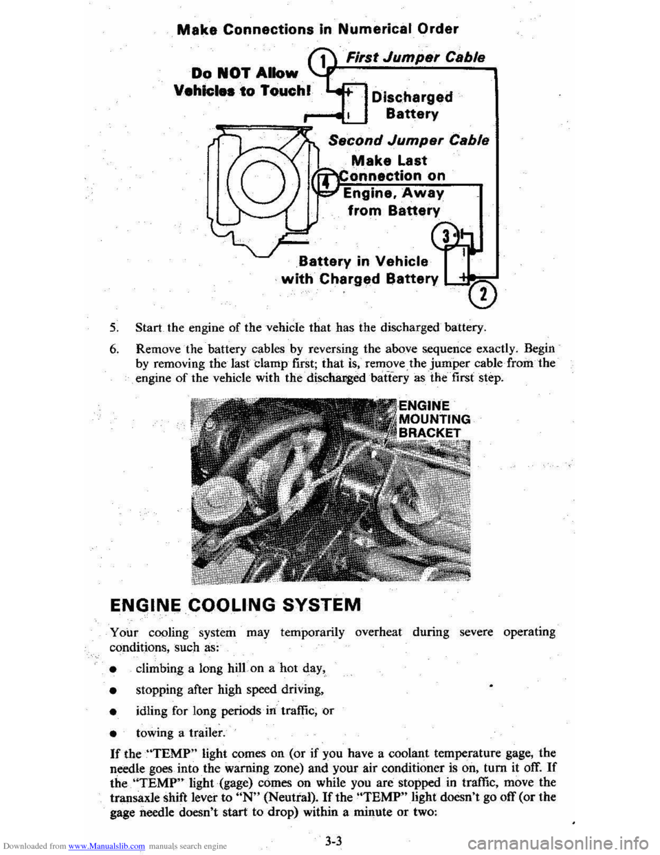
Downloaded from www.Manualslib.com manuals search engine Make Connections In Numerical Order
First Jumper Cable
Discharged
Battery
Make Last
onnectlon on
Engine. Away
from Battery
Battery in Vehicle
with Charged Battery LC"""=-
5. Start the engine of the vehicle that has the discharged battery.
6. Remove the battery cables by reversing the above sequence exactly. Begin
by removing the last clamp first; that is, remove the jumper cable· from the engine of the vehicle with the' discha:r,g:edbatTery as the' first step.
ENGINE COOLING SYSTEM
Your cooling system may temporarily overheat during severe operating
conditions, such as:
• climbing a long hilLon a hot qay,
•
stopping after high speed driving,
• idling for long periods' in' traffic, or
• towing a trailer.
If theUTEMP" light comes on (or if you have a coolant temperature gage, the
needle goes
into the warning zone) and your air conditioner is on, tum it off. If
the. 'ITEMP" light (gage) comes on while you are stopped in traffic, move the
transaxle shift lever to UN" (Neutral). If the "TBMP" light doesn't go off (or the
gage
needle doesn't start to drop) within a minute or two:
3-3
Page 51 of 95
Downloaded from www.Manualslib.com manuals search engine • pull over-to a 'safe p'late and stop (he car:-=Set the parking brake and shift to "P"(Park) (with a manual transaxle. shift to Neutral first, then set the parking
brake).
• DON'T TURN OFF THE ENGINE AND DON'T INCREASE THE ENGINE SPEED~ Let the engin e run at normal idle speed for two or three
minutes.
If the
''TEMP'' light still doesn't go off (or the gage needle doesn't start to drop) , NOW TURN OFF THE ENGINE and proceed as follows.
CAUTION: Keep henda, tools end clothing awey from'the engine COOling fen to help prevent personal Injury. This fen ia electric end can come on whether or not the eR8ine is runnirl'jJ. The fan Cen etert eutomatically in reapon .. to a heet ~, wrth the ignitkNl in ~Run."
• Lift the engine hood. Look at the coolant level.in the "see through " coolant
recovery tank. The coolant level should be at or above the "Fun Hot" mark
o n the tank.
If it looks like the coolant is boiling, wait until it stops before
proceeding You should :not need to remove the radiator cap to check the
coolant level and it can be dangerous if the coolant is still hot. See the
following Caution.
CAUTION: To help avoid the dange, of being burned:
• cia not remove the coolent recov.ry tank cap while the coolant is boiling.. and
• cia not remove the .rad~:_c.p white the engine end radiator are atill hot.
Scelding fluid and ateam can be blow, Qut under presau,.. If either cap ia taken off too soon.
• If the coolant level is low:
• look for leak s at the radiator hoses and connectio ns, heater hoses and
connections. radiator, and water pump.
See that the water pump belts
are not
brok~ or otT the pulleys and that the fan runs when the engine is running and theUTEMP" light ison (or the gage needle is in the
warning zone).
• add coolant to the recovery tank.
If the level in the recovery tank is at the correct level and the "TEMP" light (gage) still comes on, air may be-trappedin the, cooling system . This may prevent coolant
from returning to the radiator.
In this case. you may have to add coolant directly
to th e radiator.
See "Coolant Replacement" in "Service and Maintenance," Section 5 of this manual. Follow steps I and 10 for the correct way to remove
the radiator cap and add coolant to the radiator.
After the "TEMP" light is out (or the gage needle is out of the warning zone).
resume driving
at a reduced speed. Return to normal driving after about ten
minutes if the light does not come back on (or the gage needle does not go back
into the warning
~one).
J.4
Page 52 of 95
Downloaded from www.Manualslib.com manuals search engine I COMPACT SPAul
*( ~
Y' v.
~
I ~-C( -"""-c I NO SPARE I • G@1J;"~j ((?)lie, __ ,". ::..-_~.c_
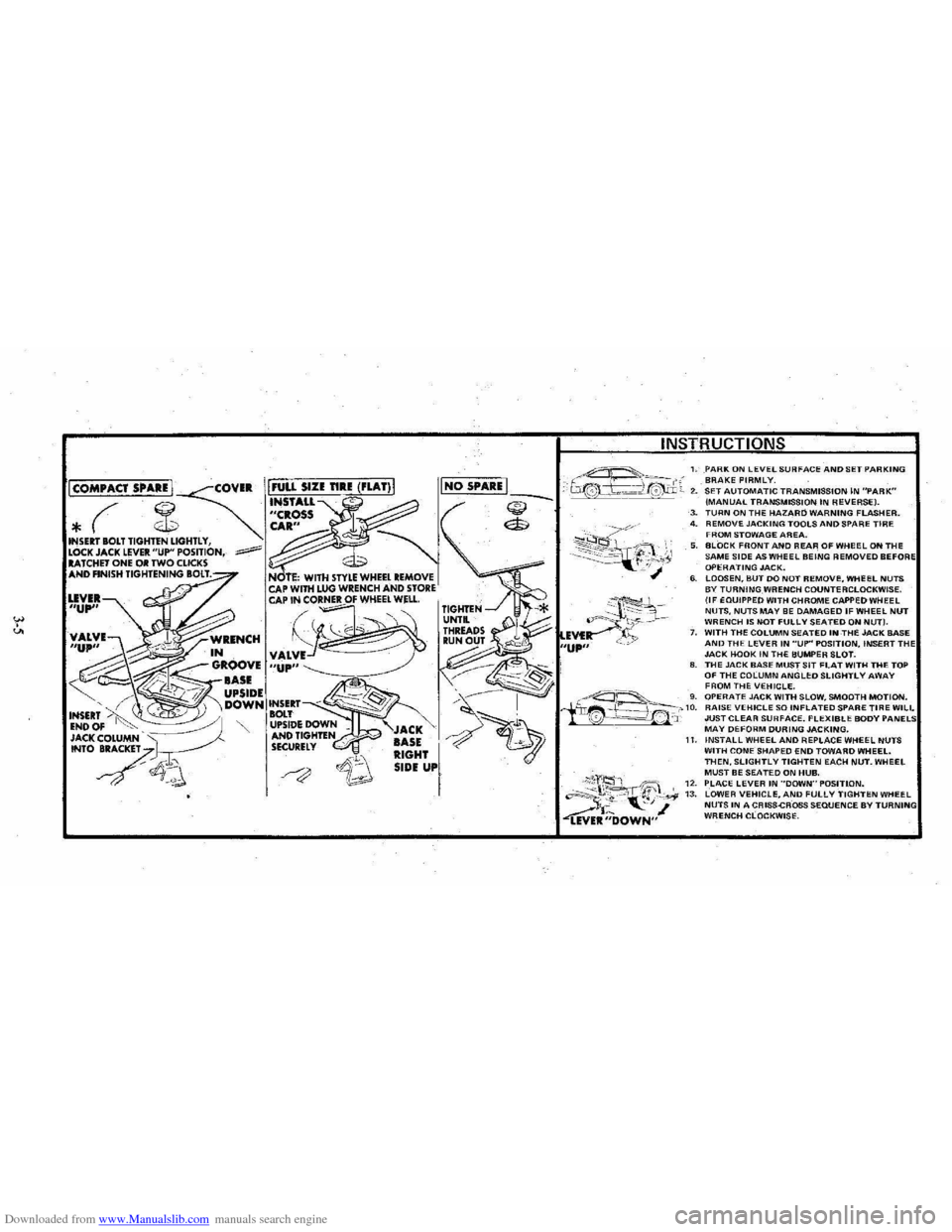
1. PARK ON lEVEL SURFACE AND SET PARKING BRAKE FIRMLY. 2. SET AUTOMATIC TRANSMISSION IN "PARK" (MANUAL TRANSMISSION IN REVERSE). ~ ($
~~~~?~;y,
3. TURN ON THE HAZARD WARNING FLASHER. 4. REMOVE JACKING TOOLS AND SPARE TIRE FROM STOWAGE AREA. 5. BLOCK FRONT AND REAR OF WHeEL ON THE SAME SIDE AS WHEEL BEING REMOVED BEFO OPERATING JACK. 6. LOOSEN, BUT DO NOT REMOVI:, WHEEL NUTS BY TURNING WRENCH COUNTERCLOCKWISE. (IF EQUIPPED WITH CHROME CAPPED WHEEL NUTS, NUTS MAY BE DAMAGED IF WHEEL NUT WRENCH IS NOT FULLY SEATED ON NUT). 7. WITH THE COLUMN SEATED INTHE JACK BASE AND THE LEVER IN "UP" POSITION, INSERT TH JACK HOOK IN THE BUMPER SLOT. 8. THE JACK BASE MUST SIT FLAT WITH THE TOP OF THE COLUMN ANGLED SLIGHTLY AWAY
I
FROM THE VEHICLE. ~---'-_ 'g. OPERATE JACK WITH SLOW, SMOOTH MOTION. iir~f~~_-'-'10. RAISE VEHICLE SO INFLATED SPARE TIRE WILL '0 --=-==!.~' 'J: JUST CLEAR SURFACE. FLEXIBLE BODY MAY DEFORM DURING JACKING.
;\;'2, 'ift;" "~~t. "-', ~ ~R;;'OWN"
11. INSTALL WHEEL AND REPLACE WHEEL NUTS WITH CONE SHAPED END TOWARD WHEEL. THEN. SLIGHTLY TIGHTEN EACH NUT. WHEEL MUST BE SEATED ON HUB. 12. PLACE LEVER IN ··DOWN"POSITlON. 13. LOWER VEHICLE. AND FULLY TIGHTEN WHEEL NUTS IN A CRISS-CROSS SEQUENCE BY WRENCH CLOCKWISE.
Page 77 of 95
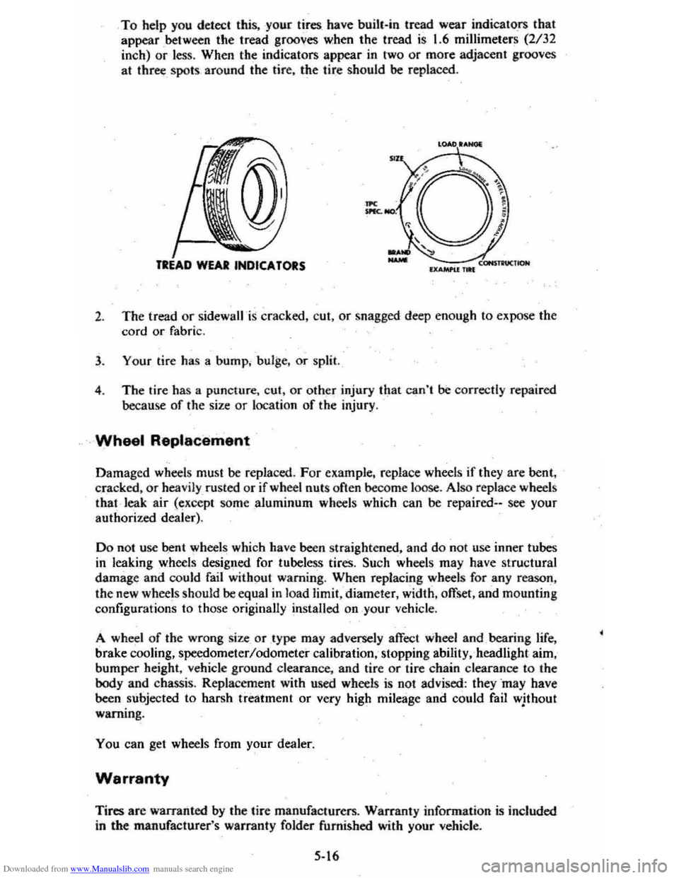
Downloaded from www.Manualslib.com manuals search engine To help you detect this, -your tires have bui1t-in tread wear indicato .fS that
appear between the tread grooves when the tread is 1.6 millimeters (2/32
inch)
or less . When the indicators appear in two or more adjacent grooves
at
three _ spots around the tire, the tire should be replaced .
LOAD lANal
''-----7.cONSTll"UCtlON IXAMI'U 1 .. 1
2. The tread or sidewall is cracked, cut, or snagged deep enough to expose the
cord
or fabric.
3 . Your tire has a bump . bulge. or split.
4 . The tire has a puncture . cut ,
or other injury that can't be correctly repaired
because of the size
or location of the injury .
. Wheel Replacement
Damaged wheels must be replaced . For example. replace wheels if they are bent .
cracked .
or heavily rusted or if wheel nuts often become -loose . Also replace wheels
that leak air (except someaJuminum wheels which can be repaired;.-see your
authorized dealer).
Do not use bent wheels which have been straightened, and do not use inner tubes
in leaking wheels designed for tubeless tires. Such wheels may have structural
damage and could fail without warning. When replacing wheels for any reason,
the new wheels should
be equal in load limit, diameter, width, offset, and mounting
configurations to those originally installed on your vehicle.
A wheel
of the wrong size. or type may adversely affect wheel and. bearing life,
brake cooling, speedometer/odometer calibration,· stopping ability, . headlight aim,
bumper height, vehicle ground clearance, and tire
or tire chain clearance to the body and chassis. Replacement with used wheels is not advised: they ·may have
been subjected to harsh treatment or very high mileage and could fail wjthout
warning .
You can get wheels from your dealer.
Warranty
Tires are warranted by the tire manufacturers. Warranty information is included
in the manufacturer's warranty folder furnished with your vehicle.
5-16
Page 86 of 95

Downloaded from www.Manualslib.com manuals search engine FUSES AND CIRCUIT BREAKERS
The wiring circuits in your vehicle are protected from short circuits by a combination of fuses, circuit breakers; and fusible thermal links in the wiring itself. This greatly reduces
the hazard of electrically caused fires in the automobile.
The fuse junction box is located under the right side of the instrument panel.
The
headlight wiring is protected by a circuit breaker in the light switch. An electrical overload will cause the lights to go on an,d off, or in some cases to remain off. If this happens , have your headlight wiring checked right away. Besides a fuse, the windshield wiper motor is also protected by a circuit breaker. If the motor overheats, due to overloading caused by heavy snow, etc., the wiper ·will remain stopped until the motor cools. Be sure to have the cause of the over· loading corrected. Circuit breakers for power windows and power door locks are located on the bulkhead in the engine
compartment.
CIRCUIT RATING
Radio ........................................... 10 Amp.
Wiper
......... ......................... ......... 25 Amp .
Stop, .Rear & Front, Hazard Lamps, I.P. Indicators .. 20 Amp.
Dir.
Sig .. B.U. Lamps .............................. 20 Amp.
Heater,
AlC .............. ........................ 25 Amp .
Inst. Lamps, Radio Dial Lamp, Heater Dial Lamp, WIS Wiper Lamp, Cigarette Lighter & Ash Tray Lamp .. 5 Amp.
Gages Warning Lamps, Cruise Control , Brake Alarm,
Oil, Rear Defogger, Fuel Gage, Headlight Buzzer, Seat Belt Warning Buzzer, Temp., Gen., Idle Stop . 20 Amp.
Glove
Box Lamp, Dome Lamp, Luggage Lamp, Clock, Hood, Cigarette Lighter, Courtesy Lamps,
Key Warning .................................... 20 Amp.
Tail, Parking and
Side Marker Lamps, License Lamp 20 Am·p.
Choke Heater . . . . . . . .. .. .. . .. . . . . . . . .. . . . . 20 Amp .
Do
not use fuses of higher amperage rating than those recom· mended above.
Fusible Links are incorporated into the wiring system. These
are wires
of such a gage that they will fuse (or melt) before damage occurs to an entire wiring harness in the event of an electncal overload. See your Chevrolet Dealer if 1usible link replacement becomes necessary.
7-4
•
Page 88 of 95
Downloaded from www.Manualslib.com manuals search engine Air Cleaner ...... . Air Conditioner
Automat ic ............ . Malnt.nance Air Pre •• ur •. Tire .... A ir Vents ..... Alternator (GEN) Light .. Aluminum Car •.. AM or AM·fM R.dios ..... Antifra.z . ..... ......... .......... . App.aranc. Car ...... Ashtrays & l ighters. Assi.tance. Owner .. Autom.tic DOOf lOCks
Autom.tic: Trann.l. Malnt.mimc. Operation .. Operating Tip$ ..... Axl. , Drive .. Sabies, Reatraint of . San Joints S.ttary
5-8
2 -
22 5·10 5·11 2·21 2·17 .-. 2·24 (S •• "Coolant") '-1 2-20 0-1 1-2
5-. ,-a 2 ·10 5-8 1·10 5-8
Em.rgency SIIHting.. 3-1 Fr •• dom .... 5·9 G •• Caution... 3-1 ; GEN Light ... 2·11 T •• t Indicator... 5·9 Befortl Oriylng Your V.hicle ,., Belt •. Seat .... M. (S .. "Seat Baits",
Blower, H.at.r &. Air Cond.... 2-20 Body Oamag... 4·4 Brak.s Adjustment P.dal Trav.l Traller 'Towing .. Warning Light Bre.ka,., Circuit
Break·ln Period, N.w V.hicl •... Bright Headlights .....
2-14 2·14 1 -11 2·17 7-4 2-' 2·7,2·14 4-4 1 -3.7·4 1-12 3-6 {S •• "Sound"l 2·18, 5-2
Bright Metal CI.aning ......... .. Bl,llbs lit Fu ••• Bumpe ... lit Hitch ••.. 81,1mper Jack Operetion Bun.r •.. C·4 Syst.m .. C •• Coolant RaeoV.ry Tenk .. FI,I.I. Powar St •• ring .... R.diator ..... . Cap.city. Cargo W.ight ... .•. Cap3Cme •. Fluid .. C.r Br.ak·ln Period , N.w ..... . C.r Chemic. I ......... .. C.rbon Monoxid. Caution
'-5 Inside Back Cover .-a '-7 6-12 7-1 2-' '-7 '-1 C.r. &. CI.aning, Appear.nce 4-1 C.rgo Capacity. 5-10 Cargo on Roof, C.rrying.. ......... ............... 1·3 CargoR.ck, Roof ..... 2·29 Cargo Coyer .. ................ ........... 2-27 CATALYST Indic.tor..... 2 ·18 C.t.lytic Conv.n.r C ·4 System ......... . Chains, Tir • ..... Ch.nging Whe.'s • Tiras .. Ch.rging Systam Indicator .... CHECK ENGINE light..
2·18,5--2 5·14 3-6 3-2 2-18, 5-2
7-6
Checklist. Driver ....... . Child Seats lit Ra.traint •.. Chrome Protection .. Cigarette lightar .... Circuit Breakars . Citizens Band Radio ... " .... " .... " .. M ••••••• Cleening .. Clock
Cloth Trim Car." .. Clutch Pedal Adjl,lstment.. .. Cold Welther Stlrting ..... Compla int Procedure ..
1-1 1-10 .-. 2·20 7-' 2·2 ~ 4-1 2·20 .-, 5-8 '-a 6-1
Conditionar, Air ....... (See "Air Conditi on.r") Con.umer Relations... 6-1
Cony.)! Mirror ... C ooling System Antifraet. ICoolant, .. Overheating .. Recovary Tank .. S.rvice .. Thermostat .. CorrOSion Protection Countries. Oper.ting in Foraign ..... Cruise Control .. Cu.tomer Sarvice .. Oamage. Sheet M.tal...-. D.fogger. Rear Window. Defro.hlT , Windshiflld .. Oalay Wipers .. Descend .ing a Grade Trail.ring .. Dimen.ion. Dimmer Switch, H.adlight Dipsticks
Engine Oil .. Power Staering .. Diractional Sign." .... . Oi.c Br~ ••.. Door lock ......
Drrve lOOe
1-3
'-5 3-3 5-S '-5 5-7 .-. 2 -3 2·12 6-1 '-5 2-21 2 -20, 2·23 '-7 '-8 1-11 7-1 2-14
'-3 .-a ,-u 2·1S 1-2 5-8 Driver Checklist.... 1·1 Driving Down Steep Gr.de........ 2·9 In Ou.ty Ar......... 5·3 on Slippery Surfaces ....... .......... ,.... 2·9 Ec;Gnomy Tips , Fu" 2·4 Electric-Powered Option...... (See "Power")
Ele<:tricel System 8IttMY ... ... .
Bulbs ...... .
Circuit Brlak.rs. , .... GEN (Glnerator) light ...... Jump Scarting .. .. Sparil Plugs .. Voltm.ter ... Erne:rg.ncy , In Ca •• of Brak. Warning Light Engine Hot light .. Freeing Vahicle When Stuck ... Hazard Warning Fla.h.r .... J.cking ..... Jump 51anlng._. Towing Clr. Emission Caution .................................. . Emi .. ion Control CAT AL YST Indicator
5-S 7-3 7-. 7-' 2·17 3-1
7-2
2·19
2·17 2·17 3-7
3-1
3 ·4 .3·5 3-1
3-7
'-1
2·19
,