1980 CHEVROLET CITATION cooling
[x] Cancel search: coolingPage 51 of 95
Downloaded from www.Manualslib.com manuals search engine • pull over-to a 'safe p'late and stop (he car:-=Set the parking brake and shift to "P"(Park) (with a manual transaxle. shift to Neutral first, then set the parking
brake).
• DON'T TURN OFF THE ENGINE AND DON'T INCREASE THE ENGINE SPEED~ Let the engin e run at normal idle speed for two or three
minutes.
If the
''TEMP'' light still doesn't go off (or the gage needle doesn't start to drop) , NOW TURN OFF THE ENGINE and proceed as follows.
CAUTION: Keep henda, tools end clothing awey from'the engine COOling fen to help prevent personal Injury. This fen ia electric end can come on whether or not the eR8ine is runnirl'jJ. The fan Cen etert eutomatically in reapon .. to a heet ~, wrth the ignitkNl in ~Run."
• Lift the engine hood. Look at the coolant level.in the "see through " coolant
recovery tank. The coolant level should be at or above the "Fun Hot" mark
o n the tank.
If it looks like the coolant is boiling, wait until it stops before
proceeding You should :not need to remove the radiator cap to check the
coolant level and it can be dangerous if the coolant is still hot. See the
following Caution.
CAUTION: To help avoid the dange, of being burned:
• cia not remove the coolent recov.ry tank cap while the coolant is boiling.. and
• cia not remove the .rad~:_c.p white the engine end radiator are atill hot.
Scelding fluid and ateam can be blow, Qut under presau,.. If either cap ia taken off too soon.
• If the coolant level is low:
• look for leak s at the radiator hoses and connectio ns, heater hoses and
connections. radiator, and water pump.
See that the water pump belts
are not
brok~ or otT the pulleys and that the fan runs when the engine is running and theUTEMP" light ison (or the gage needle is in the
warning zone).
• add coolant to the recovery tank.
If the level in the recovery tank is at the correct level and the "TEMP" light (gage) still comes on, air may be-trappedin the, cooling system . This may prevent coolant
from returning to the radiator.
In this case. you may have to add coolant directly
to th e radiator.
See "Coolant Replacement" in "Service and Maintenance," Section 5 of this manual. Follow steps I and 10 for the correct way to remove
the radiator cap and add coolant to the radiator.
After the "TEMP" light is out (or the gage needle is out of the warning zone).
resume driving
at a reduced speed. Return to normal driving after about ten
minutes if the light does not come back on (or the gage needle does not go back
into the warning
~one).
J.4
Page 66 of 95
Downloaded from www.Manualslib.com manuals search engine NOTICE: You cannot read the correct fluid level if you have just driven the car for a long time at high speed, in city traffic in hot weather, or if the car has been pulling a trailer. Wait. until the fluid has cooled down (about 30 minutes).
Remove the dipstick located on the driver's side forward of the cowl. Carefully
touch the wet end of the dipstick to find out if the fluid is cool, warm or hot. Wipe
it clean and push it back in until the cap seats. Pull
out the dipstick and read the
fluid level.
• If it felt cool or warm (about room temperature), the level should be
between the dimples above the "Full" mark.
• If it was too hot to hold. the level should be at or in the hatched area.
Add just enough DEXRON-®n fluid to fill the transaxle. It takes only 0.5 liter
(one pint)to raise the level from "Add" to "Full" with a hot transaxle.
Do not overfill the transaxle. Overfilling can cause foaming and loss of fluid, which
could result in transaxle damage.
Automatic Transaxle Drain Intervals
Change the transmission fluid and change the filter (or clean the screen) as
outlined in Section
A of the Maintenance Schedule folder.
ELECTRIC FAN
CAUTION: Keep hands, tools, and clothing away from the angine cooling fan to help prevent personal injury. This fan is electric and can come on whether or not the engine is running. The fan can start automatically in response to a heat sensor when the ignition is in the "Run" position.
ENGINE COOLING SYSTEM
The coolant recovery system is standard. The coolant in the radiator expands with
heat, and the overflow collects in the recovery tank. When the system cools down,
the coolant
is drawn back into the radiator.
The cooling system was filled at the factory with a quality coolant that meets
GM Specification 1899-M. The cooling system is designed to use coolant (a mixture
of water and ethylene glycol antifreeze) rather than plain water. The coolant
solution should be used year round. It has many advantages, such as:
• provides freezing protection down to _37°C, (-34°P)
•
provides boiling protection up to 128QC, (262°P)
•
protects against rust and corrosion in the cooling system,
• maintains the proper engine temperature for efficient operation and emission
control, and
• allows proper operation of the coolant temperature light (or gage).
See Section A of the Maintenance Schedule folder to find out when the coolant
must
be replaced.
COOLING SYSTEM CARE
Check the cooling system at regular intervals, such as during fuel stops. You
usually do not need to remove the radiator cap to check the coolant level. Lift
the engine hood and look at the "see through" coolant recovery tank. When the
engine
is cold, the coolant level -should be at or slightly above the "Full Cold"
mark on the tank. When the engine has fully warmed up, the level should be at ')r slightly below the "Full Hot" mark on the tank. If the coolant level is low,
5-5
Page 67 of 95
Downloaded from www.Manualslib.com manuals search engine remOve tlie cap on the coolant ~ecove~y tank : Add to the tank enough of a 50 150 . mixture of w ater and a g ood quality eth)dene glycol antifreez e to bring the level
up to the .
proper mark. Put the cap bac k on the tank .
Certain
conditi ons; "Such as air trapped in the syste m, may affe ct the coolant level
in
the radiator. You sho uld ch ec k the co olant ·Ievel ·in the radiator while you
change the engine oil and the e ng ine is col d. Follow steps I , 8, 9 and 10 und er
"Coola nt Rep lacement" for the correct way to rt!move the radiator cap .an d add
. coolant.
If you have to add coola nt more than f our tim es a yea r (ei ther to th e recov ery
tank
or to the radiat or). see your dealer. for a. c oo lin g system chec k.
NOTICE: If the proper quality antifreeze is used, there is no .nee~ to add extra inhibltOf"s or additives which claim to improve the svstem .. They may be harmful to the proper operation. I)f the system.
Cooling System Service
The cooling syste m should be serviced at the intervals specifi ed inSection A of
the Maintenan ce Sch edule fold er as follows:
I. W ash the radiatqr cap .and filler neck with clean water. See step J of "Coolant
Replacement" to remove rapiator cap. .
2. C hec k the coolant level in the radiator and have it tes ted for freeze proteCtion . Add·· ethylene gly col antifreeze, if needed, to· m aintain freeze protecti on at -37'C(-34'F),
3~ Have ·the coOlin-g sys tem and radiat or cap tested fo r a press ure capacity of
105 kPa (15 psi) . If a repl acement cap is needed"Hse an AC ca'p,or an
equivalent · cap, designed fOl: coolant recovery system ·s and spe cified for your model;
4. Tighten all radiator hose clamps and heater hose clamps and inspect an hose s.
R
eplace the hose s if they are swollen, "checked" or otherwise worn .
NOTICE: Take care when tightenjng·the hose clemps at tMI radiator. Overtightening COUld. bend or collapse .the radiator fittings.
5. Clean the front. of the radiator core and air condit ioning condenser to re m ove
dirt and oth er·objects. Al so clean the auxiliary engine oil andlor transmission -fluid ' cooler if the vehicle has them.
Coolant, Replacement
At the interval s specified in Section A of the Maintenance Schedule folder, flu sh
a
nd refill the cool ing system as follows :
1. Remove the·radiat or·cap when the engin e is ·cool :
•
Turn . t he cap s lowly to the len until ·it reaches a " stop. " Do not press down while turning the cap.
• 'Wait until any rem aining press ure (indicated by a hissing sound) is
reliev ed. then press down on the cap an d continue turning it t(j the left.
CAUTION:· To help ~lVoid the danger of being ,burned, do not remove the radiator cap while the angine and radiator are still hot s.c.lding flutd and steam can be bk)wn out under pressure if the·cap is taken off.too soon.
2. Whe n the cap is re m oved, run the eng ine until the upper radiator hose is hot.
(This shows that the thermostat is open and the coola nt is flow ing through
the . system.)
5·6
•
Page 68 of 95
Downloaded from www.Manualslib.com manuals search engine 3. Stop the engine. Open the radiator drain valve to drain the coolant. (Drainage
may be speeded by removing the drain plugs in the block.)
4. Close the drain valve (install block drain plugs, if removed). Add water until
the system is filled and run the engine until the upper radiator hose is hot again.
5. Repeat steps 3 and 4 several times until the drained liquid is nearly colorless.
6. Drain the system and then close the radiator drain valve tightly. (Install block
drain plugs, if removed.)
7. Disconnect all hoses from the coolant recovery tank. Remove the tank and
pour out any fluid. Scrub and clean the inside of the tank with soap and water.
Flush it well with clean water,
then drain it. Reinstall the tank and hoses.
8. Add enough water and ethylene glycol antifreeze (meeting GM Specification
1899-M)to provide the required cooling, freezing, and corrosion protection. Use a solution that is at least 50 percent antifreeze, but no more than 70
percent antifreeze. Fill the radiator to the base of the filler neck and fill the
coolant recovery
tank to the "Full Hot" mark. Put the recovery tank cap back
on.
9. Run the engine, with the radiator cap removed, until the upper radiator hose
is hot.
10. With the engine idling, add coolant to the radiator until it reaches the bottom
of the filler neck. Install the radiator cap, making sure the arrows on the cap line up with the overflow. tube.
It is the owner's responsibility to:
• Maintain cooling system freeze protection at _37°C (_34°F) to ensure
protection against corrosion and loss of coolant from boiling. (A SO/50
mixture of water and ethylene glycol antifreeze will provide freeze protection
to ~ 37°C ore -34°P.) You should do this even if you don't expect freezing
temperatures.
• Add ethylene glycol base antifreeze that meets GM Specification 1899-M
when antifreeze
hasto be added because of coolant loss or for more protection
' against freezing at temperatures lower than _37°C (-·J4°P).
NOTICE: Do not use alcohol or methanol-base antifreeze. or plain water alone. in your vehicle at any time. They will boil at a lower pOint than that at which the hot light indicator (or temperature gage) works. and they do not provide proper protection against corrosion.
Radiator Pressure Cap
The radiator cap, a 105 kPa(15 psi) pressure type, must be installed tightly,
otherwise coolant may be lost and damage to engine may result from overheating.
Radiator pressure caps should be checked periodically for proper operation.
If
replacement is required, an AC cap is recommended.
Thermostat
The engine coolant temperature is controlled by a thermostat. It stops coolant flow
through the radiator until a preset temperature is reached. This thermostat is
installed in
the engine coolant outlet on the engine block. The same thermostat is used in both winter and summer. When a replacement is needed, AC~Delco parts
are recommended.
5-7
Page 71 of 95
Downloaded from www.Manualslib.com manuals search engine 4. Lubricate hood hin 'ges.
5. Make hood -hinge and la tc h mechanism functiona l ch eck. to assure the
asse mbly
is working correctly.
Air Conditioning
Periodi cally have your Dealer check your Air Conditi oning system to be sure there
ha s been no loss in cooling output. See your Dealer immediat~ly if you suspect
the system
is not performing as it should.
Your car's air con dition ing'syste m will not operate below ambient temperatures of ~I"C (3(JF) regardless of co ntrol position.
TIRES
The tites ins tall ed on-your. vehicle are engineered to provide a proper balance of
these performa nce characteristics ~nder normal driving conditions.
• Endura nce
• Handlin g
• Noise
• Ride
• Road Hazard Resista nce
• Rolling Resistance
• Tractio n
• Tread Mileage
Thi s section contains some tips on how you can get the most benefit
from these
tire
s.
Vehicle Loading
-The tires on yo ur vehicl e -wil) perform well at aU normal loads w hen inflated
as recommended on the Tire Placa rd (located on the left front d -odr of your
vehicle) . Do not load your vehicle beyond the load limit s (total kilograms
or pounds) shown on the Tire Plac ard. The pla card tells you the design
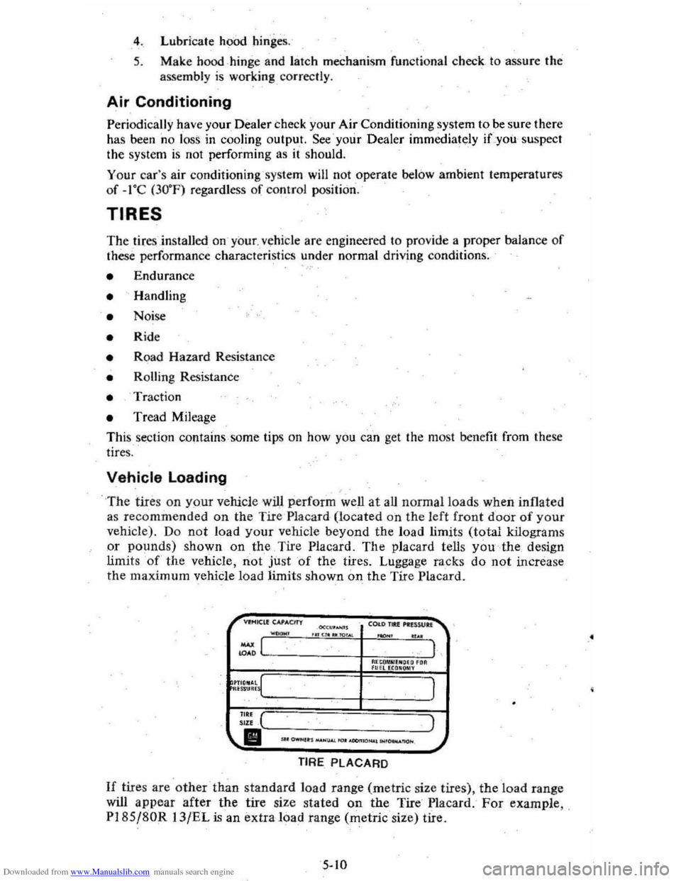
limit s 'of' the vehicle, not just 'of the tires. Luggage tacks do not increase the maxim um vehicle load limits shown on the Tire Placard.
COI.DJIU ... nWb. .n, ... ~ ... .""". .. ..
~LC-----------·--t,M.~ro""'''~,."."''~. 1 F"HEca.~Y
I
::;: ( ) "" II''--.-,----.. -,--"-~--_-_--.-_-, .-,-_--_--'...J.J
TIRE PLACARD
If tire s are other -than standard load range (metric size tires), the load range
will
appear after the tire size stated on the Tire Placard . For example , , PI8S j80R 13/EL is an extra load tange (metric size) tire.
5-10
.'
Page 77 of 95
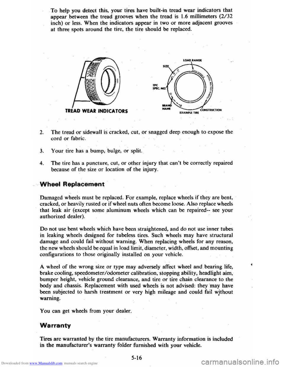
Downloaded from www.Manualslib.com manuals search engine To help you detect this, -your tires have bui1t-in tread wear indicato .fS that
appear between the tread grooves when the tread is 1.6 millimeters (2/32
inch)
or less . When the indicators appear in two or more adjacent grooves
at
three _ spots around the tire, the tire should be replaced .
LOAD lANal
''-----7.cONSTll"UCtlON IXAMI'U 1 .. 1
2. The tread or sidewall is cracked, cut, or snagged deep enough to expose the
cord
or fabric.
3 . Your tire has a bump . bulge. or split.
4 . The tire has a puncture . cut ,
or other injury that can't be correctly repaired
because of the size
or location of the injury .
. Wheel Replacement
Damaged wheels must be replaced . For example. replace wheels if they are bent .
cracked .
or heavily rusted or if wheel nuts often become -loose . Also replace wheels
that leak air (except someaJuminum wheels which can be repaired;.-see your
authorized dealer).
Do not use bent wheels which have been straightened, and do not use inner tubes
in leaking wheels designed for tubeless tires. Such wheels may have structural
damage and could fail without warning. When replacing wheels for any reason,
the new wheels should
be equal in load limit, diameter, width, offset, and mounting
configurations to those originally installed on your vehicle.
A wheel
of the wrong size. or type may adversely affect wheel and. bearing life,
brake cooling, speedometer/odometer calibration,· stopping ability, . headlight aim,
bumper height, vehicle ground clearance, and tire
or tire chain clearance to the body and chassis. Replacement with used wheels is not advised: they ·may have
been subjected to harsh treatment or very high mileage and could fail wjthout
warning .
You can get wheels from your dealer.
Warranty
Tires are warranted by the tire manufacturers. Warranty information is included
in the manufacturer's warranty folder furnished with your vehicle.
5-16
Page 83 of 95
Downloaded from www.Manualslib.com manuals search engine . SECTION 7
SPECIFICATIONS
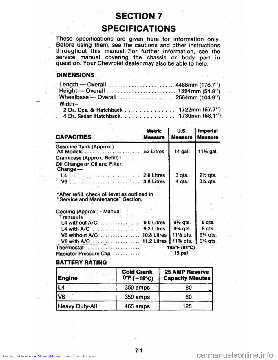
T hese specifications are given here for information on ly . B efore using them, see the cautions and other instructions
throughout this manual. For fu.rther information , see the
service manual covering the chassis or body part in question. Your Chevrol et dealer may also be abl e to help.
DIMENSIONS
Length -Overall ......... , •.... , •...... 4488mm (176 .7")
He igl;lt -Overall ......................... ':394mm (54.8 ") Wh eelbase "-Overall ................... 2664mm (104.9")
Width-2 Dr. Cpe. & Hatchback .· ............. 1722mm (67.7") 4 Dr. Sedan Hatchback.. . . . . . . . . . . . .. 1730mm (68.1 ")
Metric U .S .
CAPACITIES Mea .... .... .ur.
Gasoline rank (Approx.) All Models .................... 53 litres 14 gal.
Crankcase (Approx . Refililt Oil Change or Oil and Filter Change-
L4 ........ ........... '. ' .. ... 2.8 Litres 3 qts .
V6 . . . . . , . . . . . . . . . . . . . . . . . . . . . . 3 :8 Litres 4 qt • . .
t After refill ; check oil kwel as outlined in "Service and Mantenance " Section .
Cooling (Approx.)· Manual Tran sa x le L4 without AlC ..... . , .. .
L4 withA/C .... ... ........... .
V6 without AlC ...... ...•...... V6 with AlC ....... . Thermostaf.-.-:~-~-. -....... : ....... .
Radiator Pressure Cap
BATTERY RATING
9.0 Litre. 911 •. qls. 9.3 Litres 9¥4 qts.
to.8 Litres 1'1'12 qts.
11.2 Litres 11¥ " .c:Jts. 195"1' (91·e) 15 pal
Imperial
Me.sure
11~gal.
21f2qts .
3Ve qts.
8 qt •.
8 qts. 9V .. qts.
g¥ .. qts.
colci Crank 25 AMP Reserve
Engine .. O"F (-l8"C) Capacity Minutes
L4 350 amps 60
V6 350 amps 80
Heavy Duty "AIi 465 amps 125
7-1
Page 89 of 95
Downloaded from www.Manualslib.com manuals search engine Catalytic Converter ..................................... . 5·2 C.4S~m . CHECK ENGINE Light.. .... : ..... . 2·18,5-2 2-18,5·2 Eldla~t Gas Csution ._ .... _ ...... . Fuel Requirements IGu, ._ .... ..
SENSOR Indie.tOt' .............. . Engin.
2· 2·2 2.18 •. 5.2
e.lts .... , ........ . (See M.int.n.nce SChedule) Br •• k·ln .... . ................................. 2-2 Cod ........... . Cooling .............................. .................... . Exh.ust Ges C.ution .................... .. Flil. to St.rt ........
,.,
5·5 2· 2·0 Flooct.d ,St.rting........... 2·g Fu.1 Recommend.tion (See "Fu.1'1 I~ntification ...... _........................................ 7-5 Jump St.rting ........................... 3·1 OiL.......... ....................... (5 .. "Oil, Engine'" Overh •• ting.. ....................... . 3.3 Speclflc.tions.. ............................................ 7·1 St.rtlng. Cold Weather ........................... ".. 2·9 St.rtlng (GI,oline). 2-8 T.mp.r.ture G.g..................... ................ 2-19 T.mp.ratur. Light ..................................... 2 ·17 Th.rmostlt. ............ ..................................... 5·7 Enolne Olt.. (S .. "Oil. Enginlt '')
Ethylane Gly<:ot AntifrNZe ......... 5·6 exhauSt Gn C.U1iOfI.._ .... Exhlu.t Sy.tem Inspection .. Exterior Fini.h C.ra .............. ............... .. F.bric Care ............................................ .. F.n, Halter" Air Cond ............................ .. FASTEN SEAT BELTS Light .......... ............. . FI.tener., Repllcemant Filte~ Air CI •• n.r ... .. Fini.h C.r ... . Finilh Olm.g • .. flammable Cle.ners ................................. . FI •• ,,-,.
HI,Zlrd Wlmi"il .. Turn Signll .............................. .......... .. Flood.d Engine, St.rting .. Floor Control ....
Fluid C.p.cili ................................. ............. .. FM Radio'
2· 2· 4·4 ' ·2 2·21 \·8 5·
5 ·8 4·4
4" 4·
3 · 2-0 2·. 2·13 ,. 2·24 Folding Se.ts ........ For.lgn Countries , Operation in .. 1·5 , 2·25 2·3 Four ·W.y Hazard FI.sher ..... .. FrHdom Bett.ry ......... .......... .. FrHing C.r Wh.n Stuck. ..................... . Fue' C.p... .. ............................ ............ .. Economy Tips .. Glge .................................... .. G, •• oUne Oct.ne R.ting ................................. ........ . Ov.~e •• Oper.tion ... Tlnk C.pecity .. Fu •• Ch.ft. ......
3· 5 ·. 3·'
, . 2·' 2 ·15 2·2 2 ·2 2·3 7·
7·4 Circuit Bre ... ers ....... _................. 7-" G.ga. Engin. Temper.ture 2 ·18 Fuel ..... ...... ............ ......... 2·15 Oil Pr •• sur ... T.chometer (Engin. Sp.ed) 2·17 2·19
7·7
Volt!"etftr .............. ................................. ....... 2·19 G.soIina ......... . .......... ....... _._... (Sa. "Fu.I") GEN (G.nerator) Livht 2:17 GI ... CI •• ning ................... _ .... .... _............. '·3
Glove 8011. ............................ _....................... 2 .1 6 Gu.rd Ao-irtSt T".ft ... ~...... 2-2 Hu.rd W.rning FI.sher.. 3·1 H.adlights Circuit are.ker.. 7_. Dimm.r Switch.. 2 ·1' Instrument P.n.1 Switch.. 2 ·15 lights ON Reminder 2 -19 He.ted R .. r Window......... ................ ........ 2·2,. H.ater/Alr CondltiOfler2·20, 2·21
High·e •• m H •• dlivhts........................ 2·7
Hitches , Tr.iI.r ............................. _......... 1.12 Hood L.tcha. Iln.ide B.ck Co~r) Hood R.l"H... (Inside B.ck Cowr) Horn ............................ ......... 2.13 HOT light ........ 2 ·17
Identificltion Numbers ........................... ....... 7·5
Ignition
K.V· .... · .. · ................ . Lock In Case of Emar;ency ... Indicator L~ht •.. Infenl Se'1I " Renr.in\.. Infl.tion Pres.ure. Tires Inl.ts, Air .............................. _ .... .. Inside R •• rviaw Mirror .. Instrum.nt P.n.1 &. Controls ...
\.
2·' 3 · (SH " lightS'') 1·10 5 ·11 2·20 '·3 2·15 Int.rior ApP41.r'nce C.re . ..................... ...... ,., Interior" Instrum.nt lights.. (See "lights'" J.ck Operation&. Stowlge.. 3·5. 3.8 Jump Stlrting .......... 3~" Keys ..... 1-1 Lan. Change 8t Turn Signals 2-6 L.p-Shoulde, Baits.. {See "Seat Belts ",
Latches
Folding S •• t~c"" .. 1·5 .2 ·25 Hood ....................... .. S •• tb.c", Front.. Leather Trim Cer ...
(Ins ide Back Cover) \·5
light.r, Clgar.ne ... lights BRAKE ......... .. Brights On ..... . Bulb Ch.rt.. CHECK ENGINE ... Dimmer SwitCh , Hndlight...
Electricel Svst.m (GEN) ENGINE ( O il & /or CI\o"e) Engin. TemP41f.ture (HOT) .. FASTEN SEAT BELTS .. GEN (EI.ctric.I System) ... Hazard W.rning FI.sher ... H •• dlight Circuit br.aker H •• dlight SwitCh ... H •• dlights On Reminder HEAT (Cat.lytic Convert.r) .. High·Beam Indicator HOT: .......................................... .. Instrum.nt P.n.1 Interior .......... . OIL (Pr.ssur.) .. Parking .... Se.t B.lt Remind.r ...
4 ·3
2 -20
2·17 2· 7 '·3 2 ·18. 5·2 2·' 2 ·17 2 ·11 2 ·17 \·8
2 ·17
3 · , .. 2 ·7,2·19 2-1Q 2·18, '5-2 2·7 . 2·19 2 ·17
2 -1E1 2·19 2·17 2·" ,1 ·8