1980 CHEVROLET CITATION clock
[x] Cancel search: clockPage 33 of 95
Downloaded from www.Manualslib.com manuals search engine '" 0;
o STANDARD
o OPTIONAL
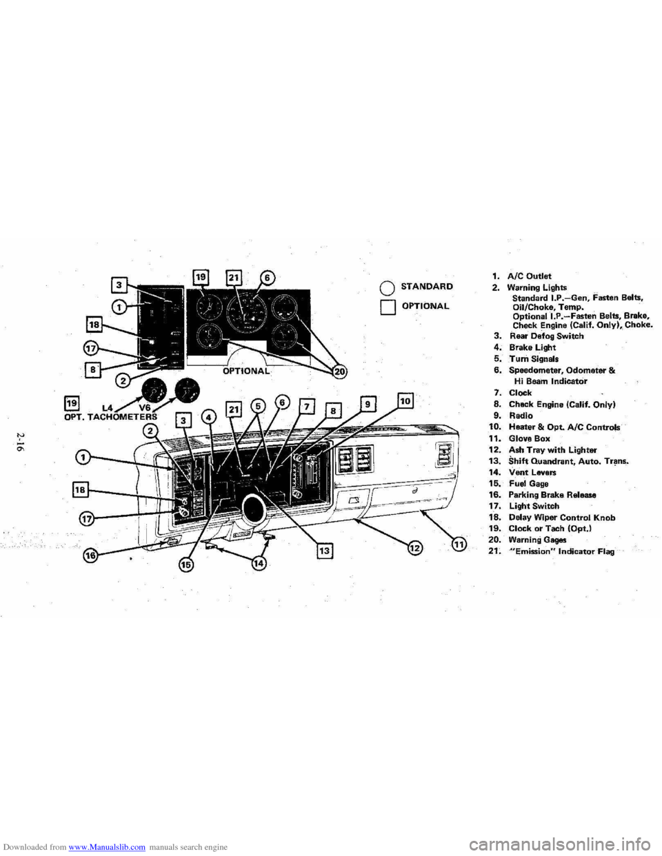
1. AIC Outlet 2. Warning Lights
Standard I.P.-Gen, Fasten Belts.
Oil/Choke, Temp.
Optionall.P.-Fasten Belts, Brake,
Check Engine (Calif. Only), Choke. 3. Rear Defog Switch
4. Brake Light
5. Turn Signals
6. Speedometer, Odometer & Hi Beam Indicator
7. Clock
8. Chack Engine (Calif. Only)
9. Radio 10. Heater & Opt. Ale Controls
11. Glove Box
12. Ash Tray with Lighter 13. Shift Quandrant, Auto. Tr~ns_.
14. Vent Levers 15. Fuel Gage
16. Parking Brake Release
17. Light Switch
18. Delay Wiper Control Knob 19. Clock or Tach (OptJ
20. Warning Gages
21. "Emission" Indicator Flag
Page 36 of 95
Downloaded from www.Manualslib.com manuals search engine Engine Temperature Gage
This gage indicat~cCX?lant temperature which will vary with air temperature and
operating condition~, The ignition must be on for accurate readings. Hard driving
or prolonged idling In very hot weather will cause the pointer to move beyond the center of the band; Should pointer move to the Red Zone, see "Engine Cooling
System" on page 3-3.
Oil Pressure Gage
The oil pressure gage indicates the pn;ssure at which oil is being delivered 10 the various parts of the engine requiring lubrication. Pressures registered by the gage
I11.!lY vary according to outside air temperatures or weight of oil being used. Oil
pressure of a cold engine ~ing operated at a given speed will be somewhat higher
than when the engine is at normal operating temperature at the same speed .
. Prolonged high speed operation on a hot day at the given speed will result in somewhat lower oil pressure readings. Readings of 30 to 40 psi (205 to 275 kPa)
mny
be considered normal during moderate road speeds of 35 to 40 mph (55 to
60 km/h) \\lith the engine at proper operating temperature. Gage readings which
are
consistently high or Im\l under these conditions may indicate lubrication system
When the engine is operating, the voltmeter indicates the electrical system voltage.
During minimum electrical load, the pointer will read to the right of the center.
As the electrical load is increased,
or in stop-and-go driving, the pointer will rotate
to the left. A meter reading continuously in
the left or right red zone indicates
an electrical system
failure .. Cause of the failure should be determined and corrected~
Light Switch
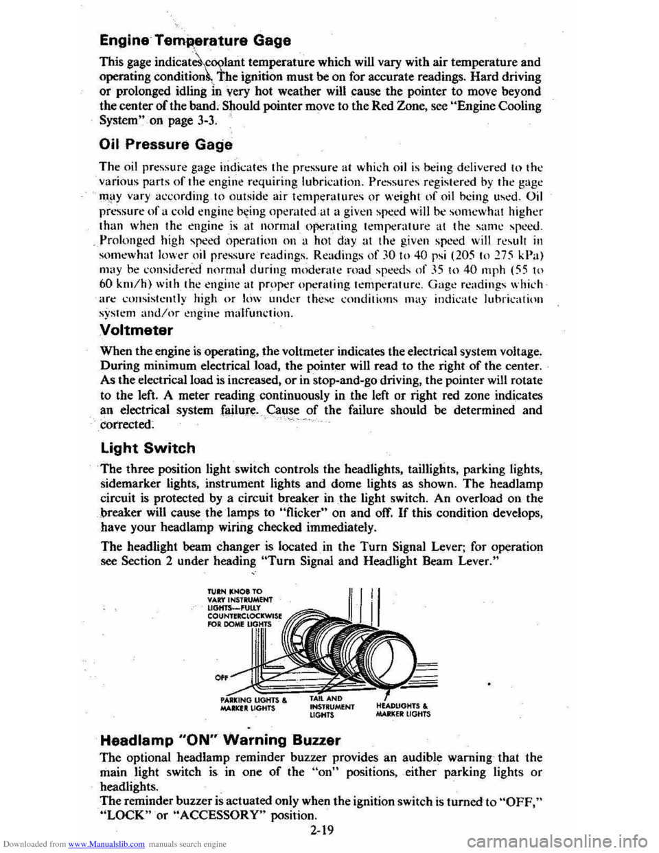
The three position light switch controls the headlights, taillights, parking lights,
sidemarker lights, instrument lights and dome lights as shown. The headlamp
circuit is protected by a circuit breaker in
the light switch. An overload on the
breaker will cause the lamps to "flicker" on and off. If this condition develops,
have your headlamp wiring checked immediately.
The headlight beam changer is located. in the
Turn Signal Lever; for operation
see Section 2 under heading "Tum Signal and Headlight Beam Lever."
TUIN KNOt TO VAr:t'INSTRUMENT lIGHTS_'UtLy COUNTERClOCKWISE RlR DOME
0"
MAltlCfIt LIGHTS , INSTRUMENT LIGHTS
Headlamp "ON" Warning Buzzer
The optional headlamp reminder buzzer provides an audible warning that the
main light switch is in one
of the "on" positions, either parking lights or
headlights.
The reminder buzzer
is actuated only when the ignition switch is turned to "OFF," "LOCK" or "ACCESSORY" position.
2-19
Page 37 of 95
Downloaded from www.Manualslib.com manuals search engine When the parking lamps or headlamps are to be operated with the key in the OFF position. the reminder buzzer can be shut off by turning the light switch knob
until the instrument cluster lights are not on.
Electric Clock
Reset the clock, . if your vehicle is so equipjled. by pulling out the knob and turning the hands clockwise if slow, counterclockwise if fast. This win, if the clock error
is five minutes or more, automatically compensate for time' gain or lag. Several
reseuings, several days apart. may be needed to properly adjust the c10ck
mechanism.
Cigarette Lighter
The optional cigarette lighter is located "in-the ash tray. To operate,- -push it in.
When it becomes heated, it automatically pops out ready for use. ,
VENTILATION. SYSTEM
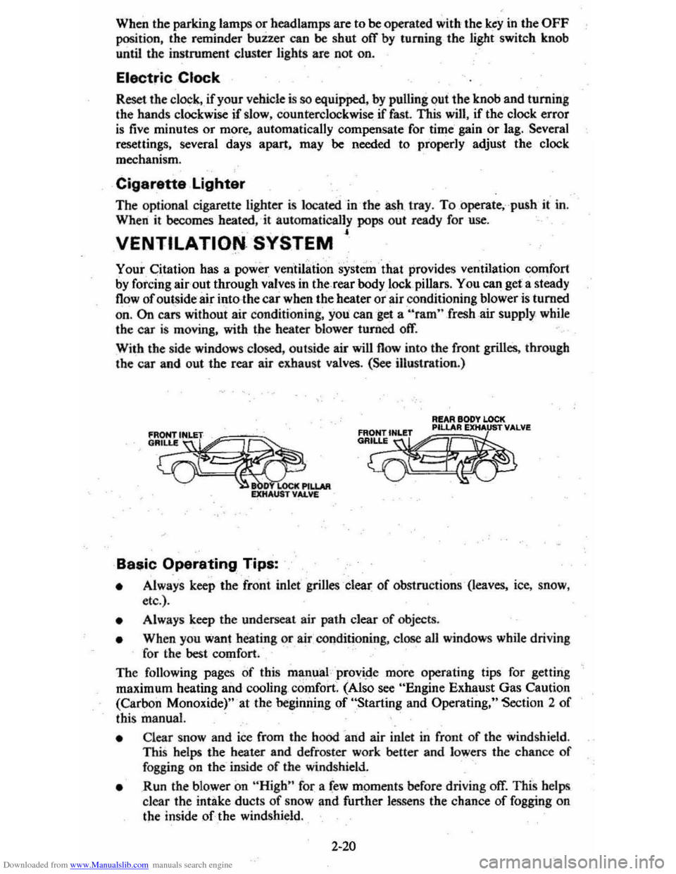
Your Citation has a power verttiI3:tion system' that provides ventilation comfort by forcing air out through valves in the rear body lock. pillars. You can get a steady
flow of outside air into the car when the heater ot air conditioning blower is turned
on, On cars without air conditioning, you can get a "'ram" fresh .air supply while
the car is moving, with the heater blower· turiled off.
With the side windows closed, outside air will flow into the front grilles. through the car and out the rear air exhaust valves. (See illustration.)
fRONrlNLET
G~.
LOCt
R!AR BODY LOCK
~~~m
• Always keep the fro'nt inlet' grilles clear of obstructions ' (leaves, ice, snow,
etc .).
• Alw.ays keep the underseat ai r path clear of objects.
• When you want heating or air COllditioning, close aU windows while driving
for
the best comfort.
The following pages of this mlin,ual provi.de more operating tips for gettina
maximum heating and cooling , comfort. (Also see "Engine Exhaust Gas Caution
(Carbon Monoxide)" 'at the begiiuling of "Starting and Operating," Section 2 of
this manual.
• Clear snow and ice from the hood 'and air inlet in front of the windshield . This helps the heater and defroster work better and lowers the chance of fogging on the' inside of the windshield.
• Run the blower on "High" for a few moments before driving off. This helps
clear the intake ducts of snow and further lessen s the chance of fogging on
the inside of the windshield.
2-20
Page 46 of 95
Downloaded from www.Manualslib.com manuals search engine Insta"ation
To install the cargo cover:
1. Insert the left hinge pin in the bracket attached to the body of the car.
2. Slide the release lever to the right to engage hinge pin in the 'bracket. See figure
B.
3. Move the lever up to lock the cover in place.
4. Reconnect the rubber 'lifting cords.
STOWING THINGS IN (OR ON) THE CAR
CAUTION: luggage or other cergo should not be piled higher than the seatbacks, When at all possible, luggage or cargo should be C8rrifHj in the trunk area. The filler panel or cargo cover, between the rear 88atback and the rear window should not be used to carry objects-even those that are small and light. All nems should be secured in place. This will help keep such things from being thrown about and Injurying people in the car during an accident. Cargo weight whether inside or on the roof, should be positioned as evenly as possible from front to rear.
ROOF LUGGAGE CARRIER
The optional roof luggage carrier is designed to allow loading of items onto the
roof
of your car. The roof luggage carrier does not increase the total load carrying
capacity of th e car , as shown opposite "Max Load" on the Tire Placard located
on the left front door. Be sure the total weight of the cargo on the roof, plus the
weight
of the cargo and passe ngers inside the car, plus the tongue load of any
trailer you are towing does
,1;10t exc_eed this "Max Load" vehicle capacity weight. See Section 5, page "5-11 for more information on Vehicle Loading . Also see the
infonnation on Trailer Towing
in Section 1 of this manual . if needed .
NOTICE:To helpayoid pOSSible damage, do not exceed 70 kilograms (1 50 pounds), cargo weight on the roof. Position the cargo in the luggage carrier as evenly as: pOssible. If carrying long items, never exceed car length and fasten such loads securely at the front and rear of the car, as well as to the luggage rack.
The roof luggage carrier consists of: five roof slats bolted to the top of the car,
two crossrails with knobs at each end th~t allow the crossrails to be adjusted or removed, and six' adjustable tie-downs.
The operation
of each item is as follows: the crossrails are easily adjusted forward
or rearward in order to help position your load. To move the crossrails , rotate
the large adjustable knob, ··No. 3" in the figure above. counterclockwise to loosen
(or remove) the crossrails and 'clockwise to tighten down the cros srails. Attached
to the top
of the crossrails are two adjustable tie-downs, "No.4" in the figure.
Ther e is also one adjustable lie-down located in the center of each outer roof slat
assembly (also called
"No.4" in the figure) . The tie-downs may be easily moved
forward and rearward within the outer slat assembly and across the top
of the
crossrails to the desired position.
To move the tie-down . rotate it countetclockwise
to loosen and clockwise to tighten down. If needed to sec ure a certain type of lead,
the tie-downs on the
crossratls may be removed and repos itioned on the outer roof
slat assemblies. While underway, periodically check to make sure that
the crossrails and the tie-downs are securely fastened to help
prevent loss of cargo, or the roof rack equipment itself.
The crossrails may be removed when not in use and stowed in the trunk or behind
the second seat on the rear load floor (with the carg o cover installed) in hatchback
style
s. When stowing the cressrails, al5..1 attach the tie-downs from the outer roof
2-29
Page 52 of 95
Downloaded from www.Manualslib.com manuals search engine I COMPACT SPAul
*( ~
Y' v.
~
I ~-C( -"""-c I NO SPARE I • G@1J;"~j ((?)lie, __ ,". ::..-_~.c_
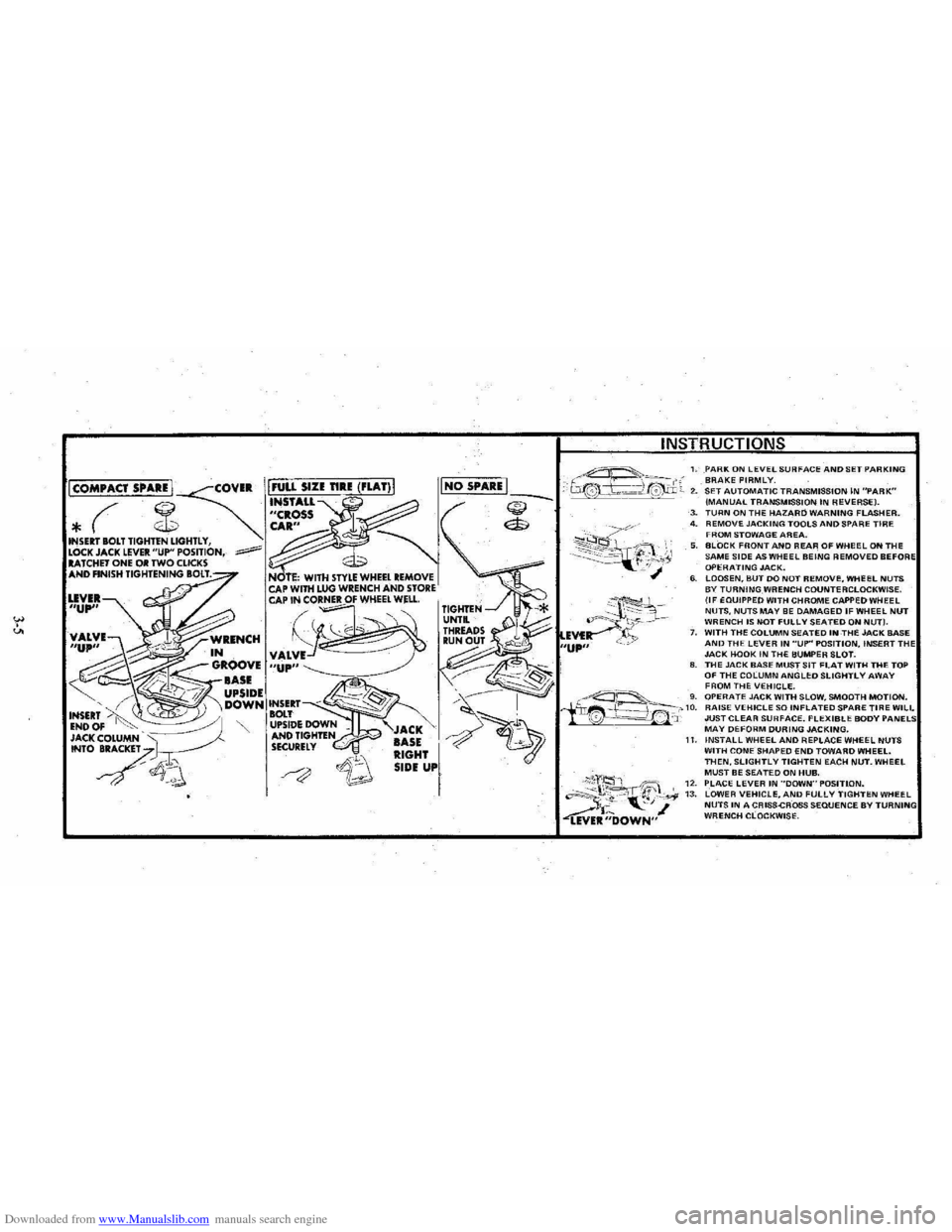
1. PARK ON lEVEL SURFACE AND SET PARKING BRAKE FIRMLY. 2. SET AUTOMATIC TRANSMISSION IN "PARK" (MANUAL TRANSMISSION IN REVERSE). ~ ($
~~~~?~;y,
3. TURN ON THE HAZARD WARNING FLASHER. 4. REMOVE JACKING TOOLS AND SPARE TIRE FROM STOWAGE AREA. 5. BLOCK FRONT AND REAR OF WHeEL ON THE SAME SIDE AS WHEEL BEING REMOVED BEFO OPERATING JACK. 6. LOOSEN, BUT DO NOT REMOVI:, WHEEL NUTS BY TURNING WRENCH COUNTERCLOCKWISE. (IF EQUIPPED WITH CHROME CAPPED WHEEL NUTS, NUTS MAY BE DAMAGED IF WHEEL NUT WRENCH IS NOT FULLY SEATED ON NUT). 7. WITH THE COLUMN SEATED INTHE JACK BASE AND THE LEVER IN "UP" POSITION, INSERT TH JACK HOOK IN THE BUMPER SLOT. 8. THE JACK BASE MUST SIT FLAT WITH THE TOP OF THE COLUMN ANGLED SLIGHTLY AWAY
I
FROM THE VEHICLE. ~---'-_ 'g. OPERATE JACK WITH SLOW, SMOOTH MOTION. iir~f~~_-'-'10. RAISE VEHICLE SO INFLATED SPARE TIRE WILL '0 --=-==!.~' 'J: JUST CLEAR SURFACE. FLEXIBLE BODY MAY DEFORM DURING JACKING.
;\;'2, 'ift;" "~~t. "-', ~ ~R;;'OWN"
11. INSTALL WHEEL AND REPLACE WHEEL NUTS WITH CONE SHAPED END TOWARD WHEEL. THEN. SLIGHTLY TIGHTEN EACH NUT. WHEEL MUST BE SEATED ON HUB. 12. PLACE LEVER IN ··DOWN"POSITlON. 13. LOWER VEHICLE. AND FULLY TIGHTEN WHEEL NUTS IN A CRISS-CROSS SEQUENCE BY WRENCH CLOCKWISE.
Page 62 of 95
Downloaded from www.Manualslib.com manuals search engine Section 5
SERVICE AND MAINTENANCE
CAUTION: As with any machine, take care when making any check, doing any maintenance. or making any repair. t6ayoid being injured. Note that some of the materials in this vehicle may be hazardous if used, serviced, or handled improperly. Improper or incomplete serVice could also lead to the vehicle itself not working properly which may result in personal injury, or damage to the vehicle or its equipment. If you have any question about carrying out some service, have the service done by 8 skilled mechanic.
REPLACEMENT FASTENERS
During car maintenance, any fasteners used to replace older ones must have the
same measurements and strength as those removed, whether metric or customary. (The numbers on the heads of metric bolts and on the surfaces of metric nuts show
their strength. Customary bolts use radial lines to show this, while most customary
nuts
do not have strength markings.) Fasteners taken from the car should be saved
for re-use in the same spot when possible. Where a fastener cannot be used again,
take care to choose a replacement that matches the old one.
For information and help, see your Chevrolet dealer.
CAUTION: This vehicle is primarily dimensioned in the metric system, Most fasteners are i'neti'icand many lire vary closein dimension to well-known customary fasteners in the inch system. Mismatched or incorrect fasteners can result in damage to the car or possibly personal injury.
MAINTENANCE SCHEDULE
For owner convenience , a separate folder has been provided with your vehicle
which contains a complete maintenance schedule. It also briefly describes the
safety, emission control, lubrication and general service your vehicle requires.
The Maintenance Schedule folder is supplemented by this section of the Owner's
Manual, as well as a Warranty Information folder also furnished with your vehicle.
Read all three publications for a full understanding
of your vehicle's maintenance
needs.
You can get a replacement Maintenance Schedule from your dealer or send the VIN(or serial) number of your vehicle to Consumer Relations, Chevrolet Central
Office, Chevrolet Motor Division, Detroit, Michigan 48202.
Fuel Cap
The fuel tank filler cap has a "screw-on ratcheting type" feature. To·remove:
•
Rotate cap counterclockwise to clear the inside of the filler neck. This
will allow any residual pressure
to escape.
• To install, reverse this procedure and tighten cap securely until a "ratcheting", clicking sound is heard indicating cap is on properly.
NOTICE: If you need to replace the fuel cap, use only a cap with these same features as specified for your model. An incorrect fuel cap can result in a serious malfunction of the fuel system or emission control system. You can get a correct replacement cap from your dealer.
5-1
Page 85 of 95
Downloaded from www.Manualslib.com manuals search engine LAMP BULB DATA
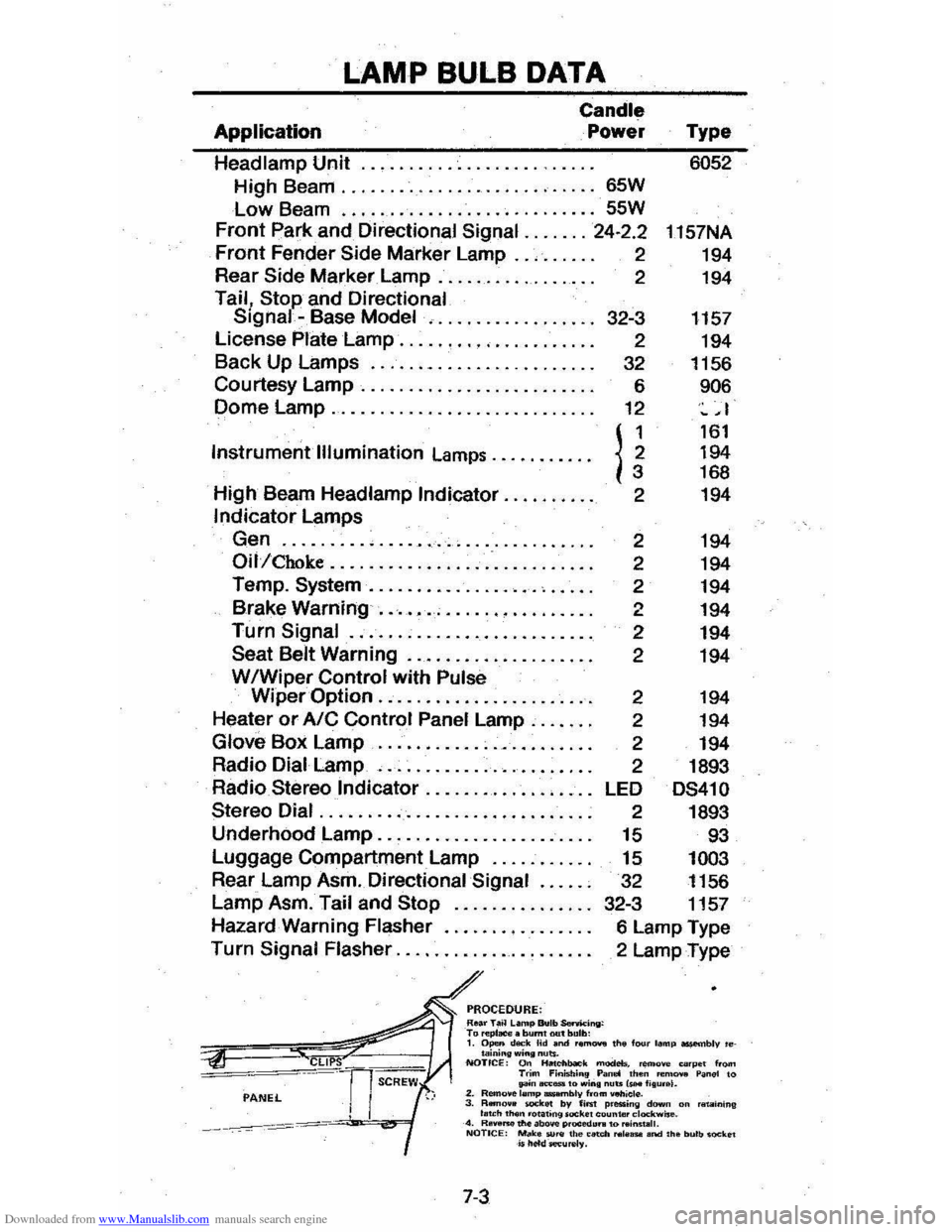
Application
Candle
Power
Headlamp Unit
.................. .
High Beam
........................... 65W
Low Beam ........................... 55W
Front park and Directional Signal ....... 24·2.2
Front Fender Side Marker Lamp .. , .. . .. . 2
Rear
Side Marker Lamp. . . . . . . . . . . . . . . . . 2
Tail, Stop and Directional Signal -Base Model , .........•....... 32-3
License
Plate Lamp ........• '" .. . . . . . . . . 2
Back Up Lamps
........................ 32
Courtesy
Lamp. . . . . . . . . . .. .. . .. . .. . .. . . 6
Dome
Lamp............................ 12
Instrument
Illumination Lamps .......... .
High Beam Headlamp
Indicator ......... .
Indicator Lamps
Gen
......... , ...................... .
Oil/Choke ......................••....
Temp. System .................. , .•...
Brake Warning ....•........•.....••..
Turn Signal ......................... .
Seat Belt Warning .................••.
WIWiper Control with Pulse
n 2
2
2
2
2
2
2
Type 6052
1157NA
194
194
1157 194
1156
906
~ ,I
161 194 168
194
194
194
194
194
194
194
Wiper
Option ....................•.. 2 194
Heater or AIC Control Panel Lamp .....• .
Glove Box Lamp ...................... .
Radio Dial Lamp
, ..................... .
Radio
Stereo Indicator ............. , ... .
Stereo Dial ............................ .
Underhood Lamp
...................... .
Luggage Compartment Lamp
.......... .
Rear Lamp Asm. Directional
Signal ..... .
Lamp Asm. Tail and
Stop .............. .
Hazard Warning Flasher
.......•........
Turn Signal Flasher .................... .
PROCEDURE: Roar T.~ L.mp Bulb SenM:ing: T., ",pI_. burnt out bulb:
2 194
2 194
2 1893
LED
DS41 0
2 1893
15 93
15 1003
32 1156
32-3 1157
6 Lamp Type
2 Lamp Type
1. Open d""k Hd and r."' ...... the f"", lamp ossembly 'etaining wing nuts. NOTICE: On lialcllbaO"k modeb. remove eo'pe t from Trim Finist.;n9 Pan.! then "'m ..... Panel to pn..,.,_.o win. nuts IsH I;Iu •• I. 2. Remo.e lemp .....,lIly from _iel". 3. RBrI.,.. _kit! by fiM p.essing dawn on 'IIt.IIining I .. ch 'h
Page 86 of 95

Downloaded from www.Manualslib.com manuals search engine FUSES AND CIRCUIT BREAKERS
The wiring circuits in your vehicle are protected from short circuits by a combination of fuses, circuit breakers; and fusible thermal links in the wiring itself. This greatly reduces
the hazard of electrically caused fires in the automobile.
The fuse junction box is located under the right side of the instrument panel.
The
headlight wiring is protected by a circuit breaker in the light switch. An electrical overload will cause the lights to go on an,d off, or in some cases to remain off. If this happens , have your headlight wiring checked right away. Besides a fuse, the windshield wiper motor is also protected by a circuit breaker. If the motor overheats, due to overloading caused by heavy snow, etc., the wiper ·will remain stopped until the motor cools. Be sure to have the cause of the over· loading corrected. Circuit breakers for power windows and power door locks are located on the bulkhead in the engine
compartment.
CIRCUIT RATING
Radio ........................................... 10 Amp.
Wiper
......... ......................... ......... 25 Amp .
Stop, .Rear & Front, Hazard Lamps, I.P. Indicators .. 20 Amp.
Dir.
Sig .. B.U. Lamps .............................. 20 Amp.
Heater,
AlC .............. ........................ 25 Amp .
Inst. Lamps, Radio Dial Lamp, Heater Dial Lamp, WIS Wiper Lamp, Cigarette Lighter & Ash Tray Lamp .. 5 Amp.
Gages Warning Lamps, Cruise Control , Brake Alarm,
Oil, Rear Defogger, Fuel Gage, Headlight Buzzer, Seat Belt Warning Buzzer, Temp., Gen., Idle Stop . 20 Amp.
Glove
Box Lamp, Dome Lamp, Luggage Lamp, Clock, Hood, Cigarette Lighter, Courtesy Lamps,
Key Warning .................................... 20 Amp.
Tail, Parking and
Side Marker Lamps, License Lamp 20 Am·p.
Choke Heater . . . . . . . .. .. .. . .. . . . . . . . .. . . . . 20 Amp .
Do
not use fuses of higher amperage rating than those recom· mended above.
Fusible Links are incorporated into the wiring system. These
are wires
of such a gage that they will fuse (or melt) before damage occurs to an entire wiring harness in the event of an electncal overload. See your Chevrolet Dealer if 1usible link replacement becomes necessary.
7-4
•