1971 CHEVROLET CAMARO window
[x] Cancel search: windowPage 12 of 88
Downloaded from www.Manualslib.com manuals search engine cushion should be as firm as
practical and just high enough
to enable the child to look
hori
zontally out of the car windows.
4. The use of the cushion should
be discontinued
as soon as the
child
is old enough to see out of
the car windows without it.
Trailer Hauling
Since passenger cars are designed
and intended to
be used primarily
as passenger conveyances, towing
a trailer will affect handling,
dura
bility and economy. Maximum
safety and· satisfaction depends
upon proper use of correct equip
ment and avoiding overloads and
other abusive operation .
The maximum loaded trailer
weight which you can pull with 5
. Do not
use shoulder belts on
children shorter than approxi
mately 4 feet 7 inches
in height.
6. General Motors recommends
that children be restrained when
riding. However, if conditions
require that a child must stand,
he should stand on the floor di-
your Camaro depends on what
special equipment has been in
stalled on your car. We do not rec
ommend pulling any trailer unless
the car
is properly equipped. In
formation on trailer hauling capa
bilities, special equipment required,
and optional equipment offered by
Chevrolet
is available from your
Chevrolet Dealer or by writing
Chevrolet Motor Division, Detroit,
9
rectly behind the front seat.
This
will minimize the possi
bility of his being thrown from
the rear
compartment during a.
sudden stop. This method
should be used only if more
complete restraint cannot be
used.
Michigan 48202.
Usage of bumper hitches
is not
recommended; however, rental
in
stallations may be made if in accord
with proper installation and usage
instructions of a reputable trailer
rental agency. Axle mounted
hitches should not be used.
To assist in attaining good
han
dling of the car-trailer combina
tion, it
is important that the trailer
Page 22 of 88
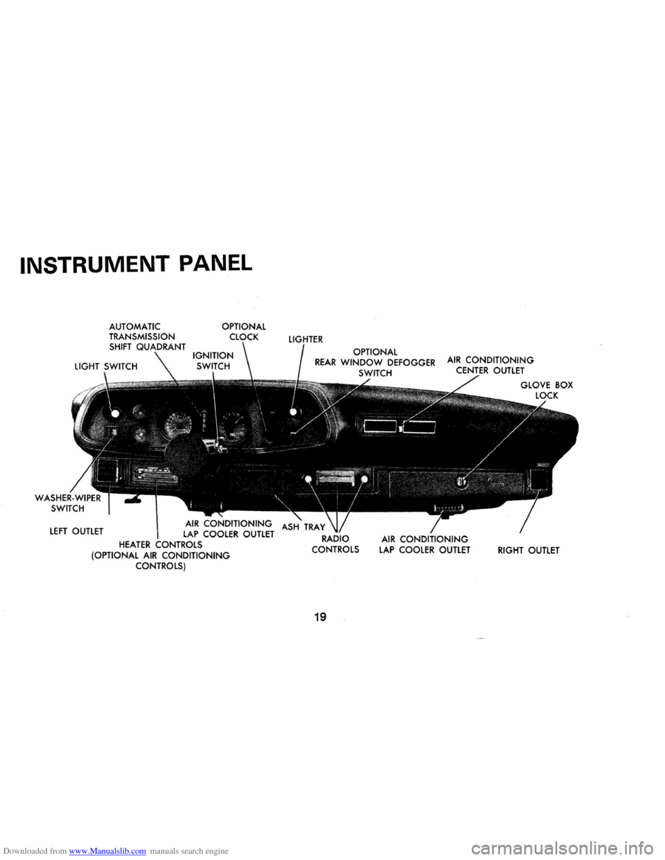
Downloaded from www.Manualslib.com manuals search engine INSTRUMENT PANEL
LEFT OUTLET
OPTIONAL
AIR CONDITIONING LAP COOLER OUTLET HEATER CONTROLS (OPTIONAL AIR CONDITIONING CONTROLS)
LIGHTER
OPTIONAL REAR WINDOW DEFOGGER SWITCH
19
AIR CONDITIONING LAP COOLER OUTLET RIGHT OUTLET
Page 28 of 88
Downloaded from www.Manualslib.com manuals search engine end vent outlet can be adjusted to
regulate or shut
off the desired
amount of conditioned air through
these outlets.
Heater
The windshield defrosting and
defogging system assists in provid
ing good visibility through desig
nated areas of the windshield under
most inclement weather conditions.
For immediate operation of the
vehicle, the windshield should be
scraped clear.
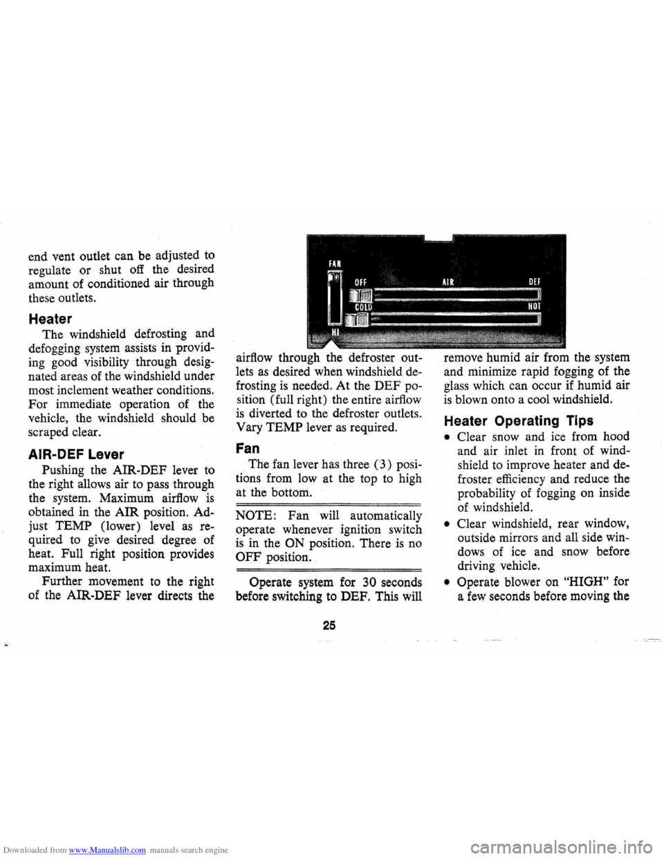
AIR-DEF Lever
Pushing the AIR-DEF lever to
the right allows air to pass through
the system. Maximum airflow
is
obtained in the AIR position. Ad
just TEMP (lower) level
as re
quired to
give desired degree of
heat. Full right position provides
maximum. heat.
Further movement to the right
of the AIR-DEF lever directs the airflow
through the defroster out
lets
as desired when windshield de
frosting is needed. At the DEF po
sition (full right) the entire airflow
is diverted to the defroster outlets.
Vary TEMP lever
as required.
Fan
The fan lever has three (3) posi
tions from low at the top
to high
at the bottom.
NOTE: Fan will automatically
operate whenever ignition switch
is in the ON position. There is no
OFF position.
Operate system for 30 seconds
before switching to DEF. This will
25
remove humid air from the system
and minimize rapid fogging of the
glass which can occur
if humid air
is blown onto a cool windshield.
Heater Operating Tips
• Clear snow and ice from hood
and air inlet in front of wind
shield to improve heater and de
froster efficiency and reduce the
probability of fogging on inside
of windshield.
• Clear windshield, rear window,
outside mirrors and all side
win
dows of ice and snow before
driving vehicle.
• Operate blower on "HIGH" for
a
few seconds before moving the
Page 29 of 88
Downloaded from www.Manualslib.com manuals search engine vehicle, to clear the intake ducts
of snow.
• Keep all windows and vents
closed to reduce dust, road and
wind noise and uncomfortable
drafts.
• For most satisfactory heater op
eration and air circulation, oper
ate fan on low or medium speeds
for normal operation and high
speed for quick warm-up and
during extremely low tempera
tures.
• For adequate rear seat heating,
the area beneath the front seat
must not be blocked by carpet
ing, rags, paper
or other mate
rial and fan should operate on
high blower.
• For additional summer ventila
tion move the
AIR lever to mid
position and the
DEFROSTER
lever to DE-ICE. If greater air
flow is desired, move the FAN
lever down to operate the three-
Rear Window Defroster
To insure clear vision through
the rear window during inclement
weather, the Rear Window De
froster has become established
as a
popular accessory. This unit draws in
air from the passenger compart
ment and directs it against the back
window to remove frost or mois
ture. Its blower has a two-speed
control switch on the instrument
panel.
Four Season Air Conditioning System
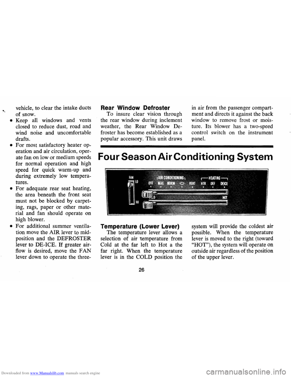
Temperature (Lower Lever)
The temperature lever allows a
selection of air temperature from
Cold at the far left to Hot a the
far right. When the temperature
lever
is in the COLD position the
26
system will provide the coldest air
possible . When the temperature
lever
is moved to the right (toward
"HOT"), the system will operate on
outside air regardless of the position
of the upper lever.
Page 30 of 88
Downloaded from www.Manualslib.com manuals search engine "
Selector (Upper Lever)
This lever provides a selection of
systems available to handle various
heating and cooling requirements
throughout the year. The positions
of the Selector lever are separated
into four (4) major operational
groups
"Off", IIAir Conditioning",
IIVent" and IIHeating". The "Air
Conditioning" and IIHeating"
groups have several positions which
improve the effectiveness of
the
system for various demands.
Fan
The fan lever has four (4) posi
tions from Lo at the top to High at
the bottom. Blower speed
is auto
matically maintained when the
ignition switch
is in the "ON" posi
tion, regardless of the position of
the selector lever. The blower re
mains
ON with the Selector lever
in the
OFF position and the igni
tion switch
ON in order to purge moisture
from the evaporator core
and distributor ducts, thereby help
ing to prevent inadvertent flash
fogging of the windows when the
system
is turned on.
Selector Lever Operation
uOFF" -Shuts the entire system off
but blower automatically remains
operative.
uMAX"-Air from the passenger
compartment is recirculated
through the system and discharged
from the upper outlets when the
temperature lever
is in "Max." cold.
(If the liTem perature" lever is
moved warmer, the system will
automatically
go on outside air.)
The
IIMax." position is used when
maximum cooling
is required under
conditions of high temperature and
humidity.
uNORMAL" -Outside air is passed
through the system and discharged
through the
Ale outlets. This posi-
27
tion is recommended for most air
conditioning situations because of
reduced blower noise and reduction
of cigarette smoke within the
ve
hicle.
uBI-LEVEL"-Outside air is passed
through the system and discharged
from both the upper and lower out
lets. This position
is recommended
for sunny cooler weather where
warm air
is required on the feet
with cooler air above to provide
comfortable breath level. Temper
ature may be adjusted
as desired.
(<> BI-Level position)
NOTE: This position will clear
fogged windows rapidly due to the
dehumidifying effect of the cooling
coils when the outside temperature
is above 30°F.
UVENT" -Air flow and tempera
ture control are the same
as "BI
Level"
except that the compressor
Page 86 of 88

Downloaded from www.Manualslib.com manuals search engine INDEX
Air Cleaner. . . . . . . . . . . . . . . . . . . . . . . . .. 55
Air Conditioning. . . . . . . . . . . . . . . . . . . .. 29
Air Pollution Control Systems ...... .... 41
Ammeter ............................ 23
Antenna ............... .............. 29
Appearance Care ..................... 47
Automatic Brake Adjusters ............ 31
Axle, Rear. . . . . . . . . . . . . . . . . . . . . . . . . .. 32
Battery .. .................... ........ 64
Bearings, Front Wheel. . . . . . . . . . . . . . . .. 58
Before Driving your Car.. . . . . . . . . . . . .. 3
Brakes
................... ........... 31 Driving Through Deep Water ........ 31
Maintenance. . . . . . . . . . . . . . . . . . . . . .. 58
Master Cylinder Level. . . . . . . . . . . . . .. 58
Parking Brake ...................... 31
Warning Light. . . . . . . . . . . . . . . . . . . .. 21
Break-In Period Cars Pulling Trailers. . . . . . . . . . . . . . . . 9
New
Car . ......................... 2
Bulbs and Fuses .
..................... 76
Bumper Jack
Operation
......... . ................ 40 Stowage ........................... 40
Carbon Monoxide Caution ......... .... 11
Circuit Breakers, Headlamps. . . . . . .. 74, 76
Cleaning ............................. 47
Clock ..
............................. 24
Clutch ..................... .......... 32
Controls ....... .... ....... ........... 31
Cooling System Care. . . . . . . . . . . . . . . . .. 60
Defogger, Rear Window
............... 26
Defroster , Defogger, Windshield ........ 25
Dimmer Switch, Headlamp . . . . . . . . . . . .. 32
Directional Signals. . . . . . . . . . . . . . . . . . .. 16
Door Locks.. . . .. . . .. . . . . . . . . . . .. .. .. 3
Emergency, In Case
Of ................ 38
Brake Warning Light. . . . . . . . . . . . . . .. 21 Generator Indicator Not
Charging. . . . . . . . . . . . . . . . . . . . . . .. 21 Hazard Warning Flasher ........... .. 38
Jacking To Change Wheels ........... 40
Jump Starting With Auxiliary
Battery .......................... 39
Overheated Radiator. . . . . . . . . . . . . . .. 39
Towing ..................... ..... .. 38
Emission Control Systems .............. 41
Engine
Cooling
........................... 60
Exhaust Gas Caution ................ 11 Flooded, Starting Procedure . . . . . . . . .. 13
Overheating. . . . . . . . . . . . . . . . . . . . . . .. 39
Specifications . . . . . . . . . . . . . . . . . . . . . .. 72
Starting . . . . . . . . . . . . . . . . . . . . . . . . . .. 13
Temperature Gauge. . . . . . . . . . . . . . . .. 23
Engine Oil
Capacity. . . . . . . . . . . . . . . . . . . . . . . . . .. 72
Change Interval. . . . . . . . . . . . . . . . . . .. 53 Dip Stick. . . . . . . . . . . . . . . . . . . . . . . . . . 52
Filter .......... .................... 53
Oil Recommendations ............... 52
Viscosity
.............. ........ . .. .. 54
Exhaust
System .................... ... 37 Filters .................... ........... 75
Flashers
Hazard Warning
.................... 38 Turn Signal. ...................... , 16
Fluid Levels
Battery
............... Inside Back Cover
Brake Master Cylinder . . . . . . . . . . . .
.. 58
Engine Oil. . . . . . . . . . . . . . . . . . . . . . . .. 52
Power Steering. . . . . . . . . . . . . . . . . . . .. 59
Radiator. . . . . . . . . . . . . . . . . . . . . . . . . .. 39
Rear Axle. . . . . . . . . . . . . . . . . . . . . . .
.. 32
Transmission. . . . . . . . . . . . . . . . . . . . . .. 56
Foreign Countries, Operation In
...... .. 65
Fuel Gauge. . . . . . . . . . . . . . . . . . . . . . . . .. 20
Full Rated Load (See Tires)
Fumes ..
........ ..... ............ .. .. 37
Fuses ............................... 76
Gasoline Filler Cap
......... 51, Inside Back Cover
Low-Lead .
........................ 42
Recommendations. . . . . . . . . . . . . . . . ..
42
Generator Indicator Light. ............. 21