1971 CHEVROLET CAMARO oil temperature
[x] Cancel search: oil temperaturePage 26 of 88
Downloaded from www.Manualslib.com manuals search engine kJ
2530 35404550
15 55
10 60
5 65 RPM/IOO 70 llllD
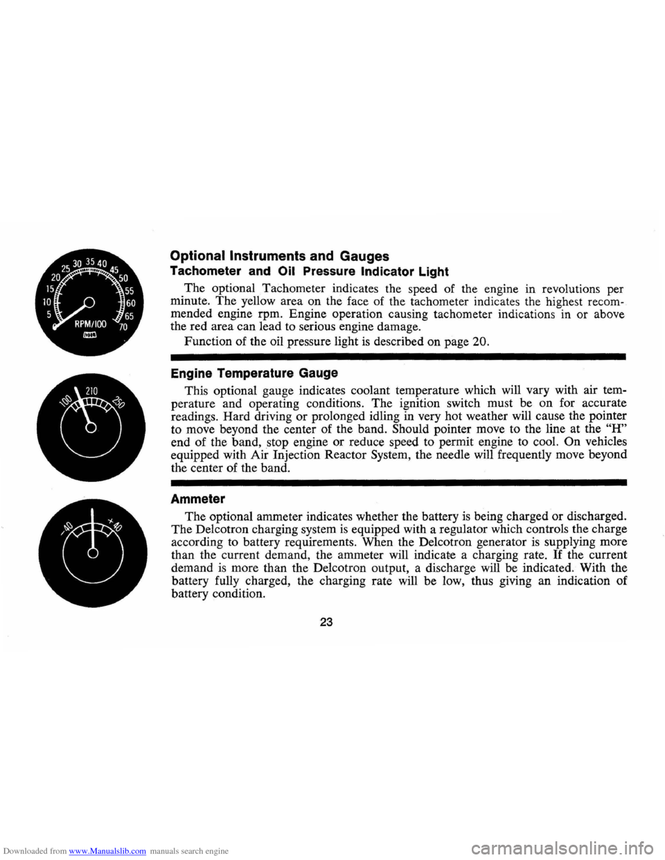
Optional Instruments and Gauges
Tachometer and Oil Pressure Indicator Light
The optional Tachometer indicates the speed of the engine in revolutions per
minute.
The yellow area on the face of the tachometer indicates the highest recom
mended engine rpm. Engine operation causing tachometer indications in or above
the red area can lead to serious engine damage.
Function of the oil pressure light is described on page
20.
Engine Temperature Gauge
This optional gauge indicates coolant temperature which will vary with air tem
perature and operating conditions. The ignition switch must be on for accurate
readings. Hard driving
or prolonged idling in very hot weather will cause the pointer
to move beyond the center of the band.
Should pointer move to the line at the "H"
end of the band, stop engine or reduce speed to permit engine to cool. On vehicles
equipped with Air Injection Reactor System, the needle will frequently move beyond
the center of the band.
Ammeter
The optional ammeter indicates whether the battery is being charged or discharged.
The Delcotron charging system is equipped with a regulator which controls the charge
according to battery requirements. When the Delcotron generator
is supplying more
than the current demand, the ammeter will indicate a charging rate.
If the current
demand
is more than the Delcotron output, a discharge will be indicated. With the
battery fully charged, the charging rate will be low, thus giving an indication of
battery condition.
23
Page 27 of 88

Downloaded from www.Manualslib.com manuals search engine Clock
Reset the clock, if your car is so
equipped, by pulling out the knob
and turning the hands clockwise
if
slow, counterclockwise if fast. This
will, if the clock error
is five min
utes
or more, automatically com
pensate for time gain or lag.
Sev
eral resettings, several days apart,
may be needed to properly adjust
the clock mechanism. Have your
clock cleaned and oiled by a com
petent clock serviceman at least
every two years.
Cigarette Lighter
The accessory cigarette lighter is
located on the instrument panel
face. To operate, push it in. When
it becomes heated, it automatically
pops out ready for
use.
Windshield Wiper
and Washer
The windshield wiping system
operates at two speeds and
is de
signed to wipe clear designated areas
of the windshield under most
inclement weather conditions. The
windshield wipers work electrically
and are not affected by engine op
eration.
Push the control lever to the
right
to start the electric windshield
wiper. The two-speed electric wiper
has both a
"low" and a "high" speed
position.
Pressing the control will send a
measured amount of water or other
cleaning agent onto the windshield
and will also cause the wiper lever
to move, thus starting the wiper
motor. The wiper will then con
tinue to operate until manually
turned off at the wiper lever.
Fill the washer jar only
% full
during the winter to allow for ex
pansion if the temperature should
fall low enough to freeze the
so
lution.
• Check washer fluid level regu
larly-do it frequently when the
24
weather is bad.
• Use GM OPTIKLEEN to pre
vent freezing damage, and to
provide better cleaning.
• Do not use radiator anti-freeze in
windshield washer; it could
cause paint damage.
• In cold weather, warm the wind
shield with defrosters before
us
ing washer-to help prevent ic
ing that may seriously obscure
vision.
Air Vents
The air vents in each kick panel
admit air from the vent grille just
ahead of the windshield. Control
knobs open and close the vents .
The amount of air entering the
car through this system
is depend
ent upon vehicle speed.
Four Season Air Conditioning
equipped cars have no kick panel
vents since the vents are a part of
the air conditioning system. The
lever beside each instrument panel
Page 30 of 88
Downloaded from www.Manualslib.com manuals search engine "
Selector (Upper Lever)
This lever provides a selection of
systems available to handle various
heating and cooling requirements
throughout the year. The positions
of the Selector lever are separated
into four (4) major operational
groups
"Off", IIAir Conditioning",
IIVent" and IIHeating". The "Air
Conditioning" and IIHeating"
groups have several positions which
improve the effectiveness of
the
system for various demands.
Fan
The fan lever has four (4) posi
tions from Lo at the top to High at
the bottom. Blower speed
is auto
matically maintained when the
ignition switch
is in the "ON" posi
tion, regardless of the position of
the selector lever. The blower re
mains
ON with the Selector lever
in the
OFF position and the igni
tion switch
ON in order to purge moisture
from the evaporator core
and distributor ducts, thereby help
ing to prevent inadvertent flash
fogging of the windows when the
system
is turned on.
Selector Lever Operation
uOFF" -Shuts the entire system off
but blower automatically remains
operative.
uMAX"-Air from the passenger
compartment is recirculated
through the system and discharged
from the upper outlets when the
temperature lever
is in "Max." cold.
(If the liTem perature" lever is
moved warmer, the system will
automatically
go on outside air.)
The
IIMax." position is used when
maximum cooling
is required under
conditions of high temperature and
humidity.
uNORMAL" -Outside air is passed
through the system and discharged
through the
Ale outlets. This posi-
27
tion is recommended for most air
conditioning situations because of
reduced blower noise and reduction
of cigarette smoke within the
ve
hicle.
uBI-LEVEL"-Outside air is passed
through the system and discharged
from both the upper and lower out
lets. This position
is recommended
for sunny cooler weather where
warm air
is required on the feet
with cooler air above to provide
comfortable breath level. Temper
ature may be adjusted
as desired.
(<> BI-Level position)
NOTE: This position will clear
fogged windows rapidly due to the
dehumidifying effect of the cooling
coils when the outside temperature
is above 30°F.
UVENT" -Air flow and tempera
ture control are the same
as "BI
Level"
except that the compressor
Page 56 of 88
Downloaded from www.Manualslib.com manuals search engine Engine Oil Change Interval
Change oil each 4 months. If
more than 6,000 miles are driven
in a 4-month period, change oil
each
6,000 miles.
In certain types of service in
cluding:
• operation under dusty condi
tions,
• trailer pulling,
• extensive idling, or
• short trip operation at freezing
temperatures (engine not
thor
oughly warmed up),
the oil change interval should not
exceed 2 months, or
3,000 miles,
whichever occurs
first. Operation
in dust storms may require an im
mediate change of oil. See your
Chevrolet dealer for advice on the
frequency of oil and filter changes under
unusual driving conditions.
The above recommendations
apply to the first change
as well as
subsequent oil changes. The oil
change interval for your Camaro
engine
is based on the use of oils
that
meet. the requirements indi
cated in the section on "Engine Oil
Recommendations." Oil change in
tervals longer than those listed
above will result in serious
reduc
tion in engine life and may affect
Chevrolet's obligation under the
provisions of the
New Vehicle War
ranty.
A high quality
MS oil meeting
General Motors Standard GM
6041-M was installed in your en
gine at the factory. It is not neces
sary to change this factory-installed
oil prior to the recommended
nor
mal change period. However, the
oil level should
be checked more
frequently during the break-in pe
riod since somewhat higher oil con-
53
sumption is normal until the piston
rings become seated.
Manifold Heat
Control Valve
Every 6,000 miles or 4 months,
check heat control valve for free
dom of operation.
If shaft is stick
ing free it up with GM Manifold
Heat Control Solvent or its equiva
lent.
Engine
Oil Filter
Replacement
The engine oil filter should be
replaced at the first oil change and
every second oil change thereafter.
This recommendation
is based on
the use of engine oils that meet the
requirements indicated in the
sec
tion on "Engine Oil Recommenda
tions," and the use of a quality oil
filter. AC
Oil Filters provide maxi
mum engine protection.
Page 57 of 88
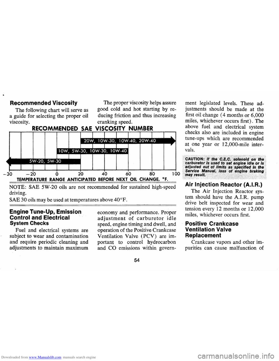
Downloaded from www.Manualslib.com manuals search engine Recommended Viscosity
The following chart will serve as
a guide for selecting the proper oil
viscosity. The
proper viscosity helps assure
good cold and hot starting by re
ducing friction and thus increasing
cranking speed.
OSITY NUMBER
-20 0 20 60 0
TEMPERATURE RANGE ANTICIPATED BEFORE NEXT OIL CHANGE. OF.
NOTE: SAE 5W-20 oils are not recommended for sustained high-speed
driving.
SAE 30 oils may be used at temperatures above 40°F.
Engine Tune-Up, Emission
Control and Electrical
System Checks
Fuel and electrical systems are
subject to wear and contamination
and require periodic cleaning and
adjustments to maintain maximum economy
and performance. Proper
adjustment of carburetor idle
speed, engine timing and dwell, and
operation of the Positive Crankcase
Ventilation Valve
(PCV) are im
portant to control hydrocarbon
and
CO emissions within govern-
54
ment legislated levels. These ad
justments should be made at the
first oil change
(4 months or 6,000
miles, whichever occurs first). The
above fuel and electrical system
checks also are included in engine
tune-ups which are recommended
at one year or 12,000-mile inter
vals.
Air Injection Reactor (A.I.R.)
The Air Injection Reactor sys
tem should have the A.I.R. pump
drive belt inspected for wear and
tension every 12 months or
12,000
miles, whichever occurs first.
Positive Crankcase
Ventilation
Valve
Replacement
Crankcase vapors and other im
purities can cause malfunction of
Page 59 of 88
Downloaded from www.Manualslib.com manuals search engine Distributor Cam Lubricator
6 Cylinder Engine -Rotate cam
lubricator
1800 at 12,000 mile in
tervals -Replace at
24,000 mile
intervals.
8 Cylinder Engine-Change cam
lubricator end for end at
12,000
mile intervals-Replace at 24,000
mile intervals.
Rear Axle
Standard -Every 4 months or
6,000 miles, whichever occurs
first, check lubricant level and add
lubricant, if necessary, to
fill to
level of filler plug hole.
Use SAE
80 or SAE 90 GL-5 Gear Lubri
cant.
Positraction -Same as standard
axle
but use only the special posi
traction lubricant available from
your Chevrolet Dealer.
Manual Transmissions
3-Speed and 4-Speed -Every
6,000 miles or 4 months-Check
at operating temperature and fill
as necessary to level of filler plug
hole with SAE
80 or SAE 90 GL-
5 Gear Lubricant.
Clutch Cross-Shaft -Every
36,000 miles or sooner if neces
sary -Remove the plug, install a
lubrication fitting
and lubricate
with water resistant
EP Chassis
Lubricant which meets
GM Speci
fication 6031M.
Automatic Transmission
Fluid Recommendations
General Motors DEXRON®
Automatic Transmission Fluid,
part no. 1050568 and United
Delco DEXRON® Automatic
Transmission Fluid, part no. 301-
RD, which have been especially
formulated and tested for use in
your automatic transmission are
recommended.
Other automatic
transmission fluids identified with
the
mark DEXRON@ are also
recommended.
56
Check the fluid level at each
engine oil change period.
To make
an accurate fluid level check:
1. Drive car several miles, making
frequent starts and stops, to
bring transmission up to normal
operating temperature (ap
proximately 180-190 OF) .
2.
Park car on a level surface.
3. Place selector lever
in "Park"
and leave engine running.
4. Remove dipstick and
WIpe
clean.
5. Reinsert dipstick until cap seats.
6. Remove dipstick and note read
ing.
If oil level is at or below the
"ADD" mark on the dipstick, oil
should be added as necessary.
One pint raises the level from ADD
to FULL.
Do not overfill.
Under normal driving condi
tions, the transmission fluid should
Page 62 of 88
Downloaded from www.Manualslib.com manuals search engine Standard Steering Gear
The steering gear is factory
filled with steering gear lubricant.
Seasonal change of this lubricant
should not be performed
and the
housing should
not be drained-no
lubrication
is required for the life
of the steering gear.
Every 36,000 miles, the gear
should be inspected for seal leak
age (actual solid
grease-not just
oily film).
If a seal is replaced or
the gear is overhauled, the gear
housing should be refilled with
Part No. 1051052 (13 oz. con
tainer)
Steering ' Gear Lubricant
which meets
GM Specification GM
4673M, or its equivalent.
NOTE: Do not use EP Chassis
Lube, meeting
GM Specification
GM 6031 M, to lubricate the gear.
DO NOT OVER-FILL the gear
housing.
Power Steering Pump
Every 6,000 miles or 4 months
Check level in pump reservoir. Fill
pump reservoir
as required with
GM Power Steering Fluid or, if
this
is not available, DEXRON®
Automatic Transmission fluid.
Oil
should be at operating tempera
ture
and wheels in straight ahead
position when checking
or filling
operation is performed to ensure
against over-filling.
Hood Latches
Every 4 months or 6,000 miles,
whichever occurs first, lubricate
hood latch assembly
and hood
hinge assembly as follows:
1. Wipe off any accumulation of
dirt
or contamination on latch
parts.
2. Apply Lubriplate
or equivalent
to latch pilot bolts
and latch
locking plate.
3. Apply light engine oil to
all
59
pivot points in release mecha
nism, as well as primary
and sec
ondary latch mechanisms.
4. Lubricate hood hinges.
5. Make hood hinge
and latch
mechanism functional check to
assure the assembly is working
correctly.
Air Conditioning
Have your Chevrolet Dealer
check your Air Conditioning sys
tem at some time during the winter
months to
be sure there has been
no loss in cooling output. During
the summer, see your Chevrolet
Dealer immediately if you suspect
the system is
not performing as it
should.
NOTE: On vehicles equipped with
a
Four Season Air Conditioning
System, the system will not operate
below ambient temperatures of
30oP. regardless of control posi
tion.
Page 63 of 88

Downloaded from www.Manualslib.com manuals search engine Cooling System Care
Checking the coolant level at
each engine oil change. Level
should be
3" below bottom of filler
neck when cold.
Coolant Recommendations
The inhibited year-around cool
ant, used to
fill the cooling system
at the factory,
is a high quality so
lution that meets General Motors
Specifications 1899-M. This fac
tory-fill coolant solution
is formu
lated to withstand two full calendar
years of normal operation without
draining, provided the same con
centration of coolant
is added if the
system needs additional fluid be
tween drain periods. The original
factory-fill coolant provides freez
ing protection to
-20°F (-32°F
in Canada).
Every two years, the cooling sys
tem should be serviced as follows:
1. Drain coolant, when hot,
through the radiator drain valve.
2. Close valve and add sufficient
plain· water to
fill system.
3. Run engine until normal operat
ing temperature
is reached.
4. Drain and refill the system as
described in steps 1, 2, and 3 a
sufficient number of times until
the drained liquid
is colorless.
5. Allow system to drain com
pletely and then close radiator
drain valve tightly.
6.
Add the necessary amount of
high quality inhibited glycol
base coolant meeting GM
Speci
fication 1899-M to provide the
required freezing and corrosion
protection
(at least to O°F.)
7. Run engine until normal oper
ating temperature
is reached.
8. Check and adjust level of cool
ant after system has cooled
suffi
ciently to remove radiator cap.
60
NOTE: Addition of supplemental
additives and other available ma
terials which have not been specifi
cally approved by GM are not nor
mally required in your car. Use of
these materials will result in un
warranted operating expense.
It is the owner's responsibility to
keep the freeze protection at a level
commensurate with the tempera
tures which may occur in the area
in which the vehicle will be oper
ated. Regardless of whether freez
ing temperatures are
or are not ex
pected, cooling system protection
should be maintained at least to
OaF to provide adequate corrosion
protection. When coolant addi
tions are required because of cool
ant loss or to provide additional
protection against freezing at tem
peratures lower than
-20°F,
(-32°F in Canada), a sufficient
amount of an ethylene glycol base