1969 FORD MUSTANG wheels
[x] Cancel search: wheelsPage 111 of 413
03-04-02
Automatic Air Leveling System — Lincoln Continental
03-04-02
REMOVAL AND INSTALLATION
COMPRESSOR
REMOVAL
1.
Raise the front of the vehicle and
place jack stands under frame side
rails.
2.
Turn the front wheels all the way
to the right. Working from the und-
erside of the left front fender, remove
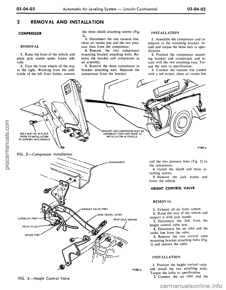
the three shield attaching screws (Fig.
2).
3.
Disconnect the one vacuum line,
clean air intake line and the two pres-
sure lines from the compressor.
4.
Remove the two compressor
mounting bracket attaching bolts. Re-
move the bracket and compressor as
an assembly.
5.
Remove the three compressor to
bracket attaching nuts. Separate the
compressor from the bracket.
INSTALLATION
1.
Assemble the compressor and in-
sulators to the mounting bracket. In-
stall and torque the three nuts to spec-
ification.
2.
Position the compressor mount-
ing bracket and compressor and se-
cure with the two attaching nuts. Tor-
que the nuts to specification.
3.
Connect the vacuum line (coded
with a red stripe), clean air intake line
BRACKET
AND
COMPRESSOR
MUST
BE
ASSEMBLED
TOGETHER
PRIOR
TO
INSTALLATION
IN
VEHICLE
BOLT MUST
BE IN
PLACE
PRIOR
TO
INSTALLATION
OF
SUPPORT
INTO
VEHICLE
FIG. 2—Compressor Installation
CROSSMEMBER
EXHAUST
VALVE PORT
OVER
TRAVEL
LEVER
REAR AXLE
HOUSING
F1400-A
3—Height Control Valve
F1420-A
and the two pressure lines (Fig. 2) to
the compressor.
4.
Install the shield and three at-
taching screws.
5.
Remove the jack stands and
lower the vehicle.
HEIGHT CONTROL VALVE
REMOVAL
1.
Exhaust all air from system.
2.
Raise the rear of the vehicle and
support it with jack stands.
3.
Disconnect the link from the
height control valve arm.
4.
Disconnect the air inlet and the
outlet line from the valve.
5.
Remove the two control valve
mounting bracket attaching bolts (Fig.
3) and remove the valve.
INSTALLATION
1.
Position the height control valve
and install the two attaching bolts.
Torque the bolts to specification.
2.
Connect the air inlet and theprocarmanuals.com
Page 115 of 413
03-05-02
Steering Columns
And
Linkage
03-05-02
which also will shear away during
im-
pact.
TILT STEERING COLUMNS
The steering column
is of the col-
lapsible type
to
lessen
the
possibility
of injury
to the
driver
of the
vehicle
should
he
become involved
in an
acci-
dent.
The
lower
end of the
steering
column tube
at the
bellows area will
collapse approximately
six
inches
upon
a
hard impact.
The shift tube
and the
steering shaft
are provided with plastic dowels
and
will shear
and
allow them
to
collapse
in proportion
to the
outer tube upon
impact.
Once
the
steering column
has
been
collapsed,
a
complete
new
column
must
be
installed.
The tilt column features nine driv-
ing positions (four
up and
four down
from
a
center position).
The
.column
also features
a
turn signal switch with
a lane-changer position turn indicating
position
and
emergency warning flash-
er control.
TILT-AWAY STEERING COLUMNS
The tilt-away steering column
fea-
tures nine driving positions (four
up
and four down from
a
center position)
and
a
tilt-away position that
is
auto-
matically accomplished
on
Mustang
and Cougar models when
the
ignition
key
is
turned
to the
OFF
position
and
the left door
is
opened.
On
Thunder-
bird models,
the
tilt-away occurs when
the shift lever
is
placed
in
PARK
and
the driverns door
is
opened.
The steering column
is of the col-
lapsible type
to
lessen
the
possibility
of injury
to the
driver
of the
vehicle
should
he
become involved
in an
acci-
dent.
The
lower
end of the
steering
column tube
at the
bellows area will
collapse approximately
six
inches
upon
a
hard impact.
The shift tube
and the
steering shaft
are provided with plastic dowels
and
will shear
and
allow them
to
collapse
in proportion
to the
outer tube upon
impact.
Once
the
steering column
has
been
collapsed,
a
complete
new
column
must
be
installed along with mounting
brackets which will also shear away
during impact.
IN-VEHICLE ADJUSTMENTS
AND
REPAIRS
STEERING WHEEL SPOKE
POSITION ADJUSTMENT
When
the
steering gear
is on the
high point,
the
front wheels should
be
in
the
straight-ahead position
and the
steering wheel spokes should
be in
their normal position with
the
Pitman
arm pointing directly forward.
If the
spokes
are not in
their normal posi-
tion, they
can be
adjusted without
dis-
turbing
the
toe-in adjustment (Part
3-1).
STEERING WHEEL
REPLACEMENT
1.
Disconnect
the
negative cable
from
the
battery.
2.
Working from
the
underside
of
the steering wheel spoke, remove
the
crash
pad
attaching screws. Lift
the
crash
pad
from
the
wheel.
(On
Conti-
nental Mark
III
models,
pry out the
crash
pad
insert
and
remove
the two
screws that secure
the
crash
pad. Re-
move
the
crash
pad. On
models
equipped with steering wheel mounted
speed controls, refer
to
Group
16 for
removal instructions). Remove
the
horn ring
(if so
equipped)
by
turning
it counterclockwise.
3.
Remove
the
steering wheel
nut,
and then remove
the
steering wheel
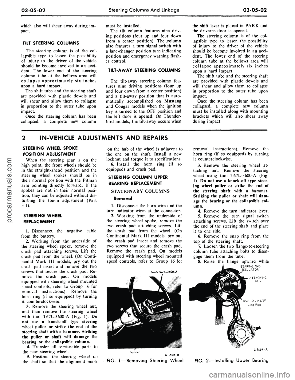
with tool T67L-3600-A
(Fig. 1). Do
not
use a
knock-off type steering
wheel puller
or
strike
the end of the
steering shaft with
a
hammer. Striking
the puller
or
shaft will damage
the
bearing
or the
collapsible column.
4.
Transfer
all
serviceable parts
to
the
new
steering wheel.
5.
Position
the
steering wheel
on
the shaft
so
that
the
alignment mark
on
the hub of the
wheel
is
adjacent
to
the
one on the
shaft. Install
a new
locknut
and
torque
it to
specifications.
6. Install
the
horn ring
(if so
equipped)
and
crash
pad.
STEERING COLUMN UPPER
BEARING REPLACEMENT
STATIONARY COLUMNS
Removal
1. Disconnect
the
horn wire
and the
turn indicator wires
at the
connector.
2.
Working from
the
underside
of
the steering wheel spoke, remove
the
two crash
pad
attaching screws. Lift
the crash
pad
from
the
wheel.
(On
Continental Mark
III
models,
pry out
the crash
pad
insert
and
remove
the
two screws that secure
the
crash
pad.
Remove
the
crash
pad. On
models
equipped with steering wheel mounted
speed controls, refer
to
Group
16 for
7oo/-T67L-3600-A
removal instructions). Remove
the
horn ring
(if so
equipped)
by
turning
it counterclockwise.
3.
Remove
the
steering wheel
at-
taching
nut.
Remove
the
steering
wheel using tool T67L-3600-A
(Fig.
1).
Do not use a
knock-off type steer-
ing wheel puller
or
strike
the end of
the steering shaft with
a
hammer.
Striking
the
puller
or
shaft will
dam-
age
the
bearing
or the
collapsible
col-
umn.
4.
Remove
the
turn indicator lever.
5.
Remove
the
turn signal switch
attaching screws. Lift
the
switch over
the
end of the
steering shaft
and
place
it
to one
side.
6. Remove
the
snap ring from
the
top
of the
steering shaft.
7.
Loosen
the two
flange-to-steering
column tube attaching bolts
to
disen-
gage them from
the
tube.
8. Raise
the
flange upward while
BEARING
AND
INSULATOR
Spacer
G 1502 -B
FIG.
1—Removing
Steering Wheel
G 1497-A
FIG. 2—Installing Upper Bearingprocarmanuals.com
Page 116 of 413
03-05-03
Steering Columns And Linkage
03-05-03
tapping the steering shaft lightly with
a plastic hammer to free the bearing
and flange from the shaft.
9. Remove the bearing and insula-
tor from the flange.
Installation
1.
Install flange bolts (square head)
in flange if they were removed. Turn
the nuts onto the bolts one complete
turn only.
2.
Position the flange onto the
steering column tube.
3.
Engage the two flange bolt heads
with the square holes in the column
tube,
then tighten the two attaching
nuts to specification.
4.
Position the bearing and insula-
tor on the shaft. Work it down onto
the shaft as far as possible, then place
a piece of 3/4 ID x 2 1/8 inch pipe
over the end of the shaft and install
the steering wheel attaching nut (Fig.
2).
5.
Tighten the nut until the bearing
is seated in the flange, then remove
the nut and pipe from the shaft.
6. Position the turn signal switch
on the flange and install the three at-
taching screws.
7.
Make certain that the wheels are
in the straight ahead position. Place
the steering wheel on the steering
shaft with the spokes in the horizontal
position. Install and torque the attach-
ing nut to specification.
8. Secure the crash pad to the
steering wheel with the two attaching
screws.
9. Connect the horn and turn signal
wires.
10.
Install the turn signal lever.
TILT WHEEL COLUMNS
Removal
1.
Disconnect the negative cable
from the battery.
2.
Remove the steering wheel with
tool T67L-3600-A (Fig. 1). Install the
spring, shipping spacer (3/4 x 1 1/8-
inch pipe) and a steering wheel attach-
ing nut on the shaft. Do not use a
knock-off type steering wheel puller or
strike the end of the steering shaft
with a hammer. Striking the puller or
shaft will damage the bearing or the
collapsible column.
3.
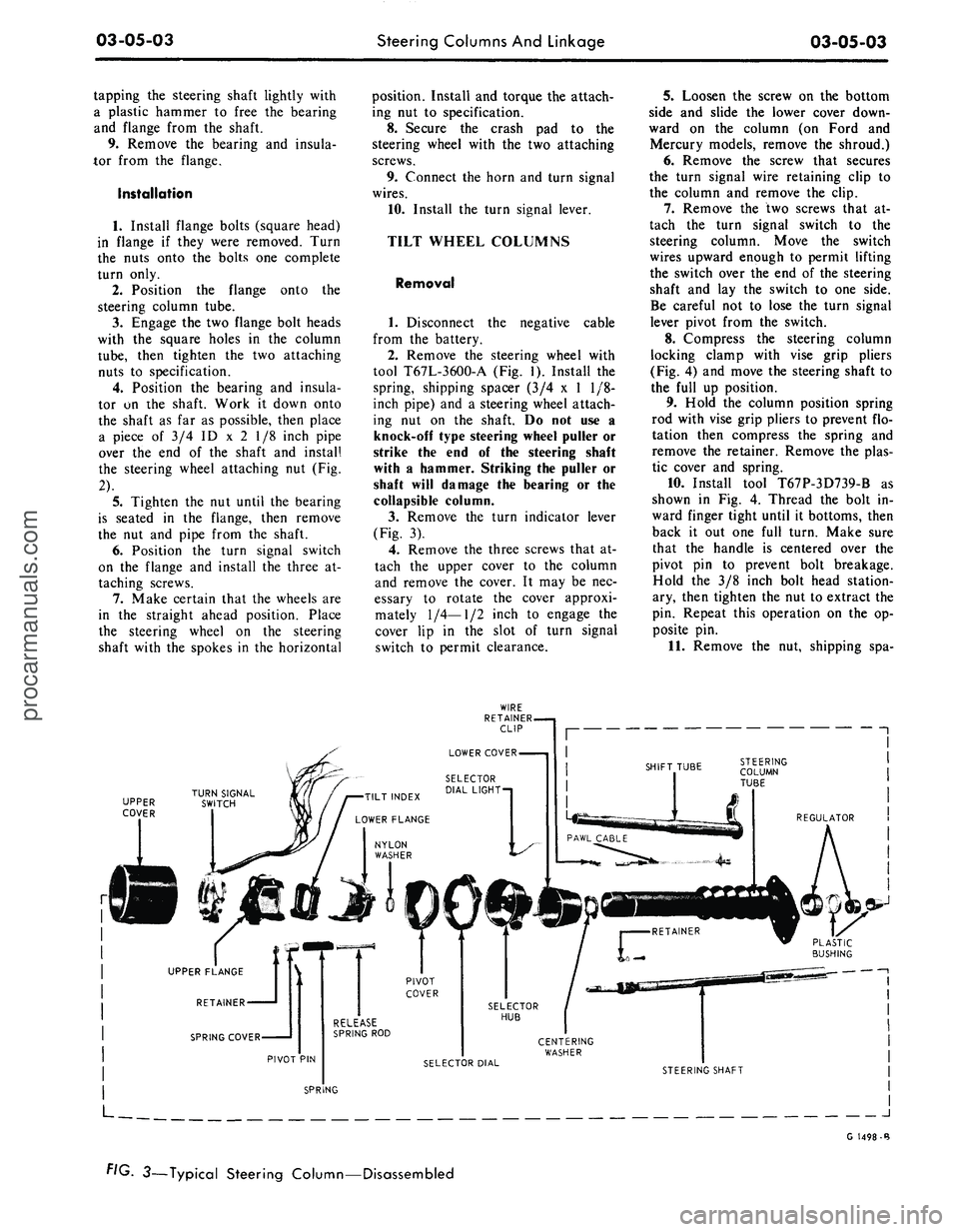
Remove the turn indicator lever
(Fig. 3).
4.
Remove the three screws that at-
tach the upper cover to the column
and remove the cover. It may be nec-
essary to rotate the cover approxi-
mately
1/4—1/2
inch to engage the
cover lip in the slot of turn signal
switch to permit clearance.
5.
Loosen the screw on the bottom
side and slide the lower cover down-
ward on the column (on Ford and
Mercury models, remove the shroud.)
6. Remove the screw that secures
the turn signal wire retaining clip to
the column and remove the clip.
7.
Remove the two screws that at-
tach the turn signal switch to the
steering column. Move the switch
wires upward enough to permit lifting
the switch over the end of the steering
shaft and lay the switch to one side.
Be careful not to lose the turn signal
lever pivot from the switch.
8. Compress the steering column
locking clamp with vise grip pliers
(Fig. 4) and move the steering shaft to
the full up position.
9. Hold the column position spring
rod with vise grip pliers to prevent flo-
tation then compress the spring and
remove the retainer. Remove the plas-
tic cover and spring.
10.
Install tool T67P-3D739-B as
shown in Fig. 4. Thread the bolt in-
ward finger tight until it bottoms, then
back it out one full turn. Make sure
that the handle is centered over the
pivot pin to prevent bolt breakage.
Hold the 3/8 inch bolt head station-
ary, then tighten the nut to extract the
pin. Repeat this operation on the op-
posite pin.
11.
Remove the nut, shipping spa-
UPPER
COVER
J
G 1498-B
FIG. 3—Typical Steering Column—Disassembledprocarmanuals.com
Page 122 of 413
03-05-09
Steering Columns And Linkage
03-05-09
FAIRLANE, FALCON
AND MONTEGO
Removal
1.
Disconnect the battery cable
from the negative post.
2.
Disconnect the turn signal switch
wires at the connector.
3.
Disconnect the neutral start
siwtch (with automatic transmission)
and back-up light switch wires from
the switches.
4.
Disconnect the transmission con-
trol rod(s) from the lever(s) at the
lower end of the column.
5.
Remove the bolt that secures the
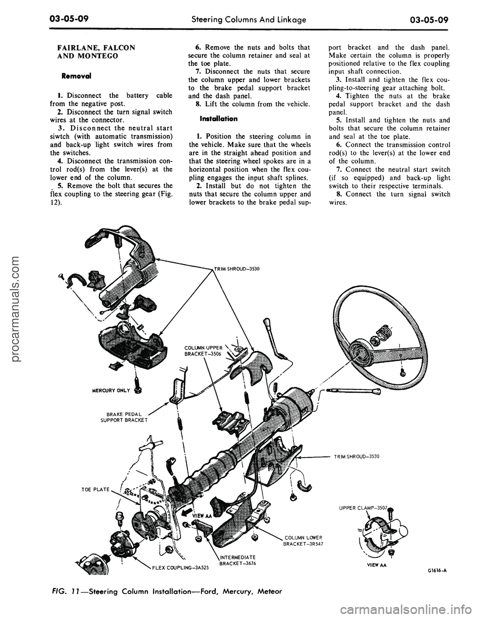
flex coupling to the steering gear (Fig.
12).
6. Remove the nuts and bolts that
secure the column retainer and seal at
the toe plate.
7.
Disconnect the nuts that secure
the column upper and lower brackets
to the brake pedal support bracket
and the dash panel.
8. Lift the column from the vehicle.
Installation
1.
Position the steering column in
the vehicle. Make sure that the wheels
are in the straight ahead position and
that the steering wheel spokes are in a
horizontal position when the flex cou-
pling engages the input shaft splines.
2.
Install but do not tighten the
nuts that secure the column upper and
lower brackets to the brake pedal sup-
port bracket and the dash panel.
Make certain the column is properly
positioned relative to the flex coupling
inpui shaft connection.
3.
Install and tighten the flex cou-
pling-to-steering gear attaching bolt.
4.
Tighten the nuts at the brake
pedal support bracket and the dash
panel.
5.
Install and tighten the nuts and
bolts that secure the column retainer
and seal at the toe plate.
6. Connect the transmission control
rod(s) to the lever(s) at the lower end
of the column.
7.
Connect the neutral start switch
(if so equipped) and back-up light
switch to their respective terminals.
8. Connect the turn signal switch
wires.
COLUMN UPPER \
BRACKET-3506 V
BRAKE PEDAL
SUPPORT BRACKET
TRIMSHROUD-3530
UPPER CLAMP-3507,
COLUMN LOWER
BRACKET-3R547
•
FLEXCOUPLING-3A525
^INTERMEDIATE
BRACKET-3676
VIEW AA
G1616-A
FIG. 11—Steering Column Installation—Ford, Mercury, Meteorprocarmanuals.com
Page 123 of 413
03-05-10
Steering Columns And Linkage
03-05-10
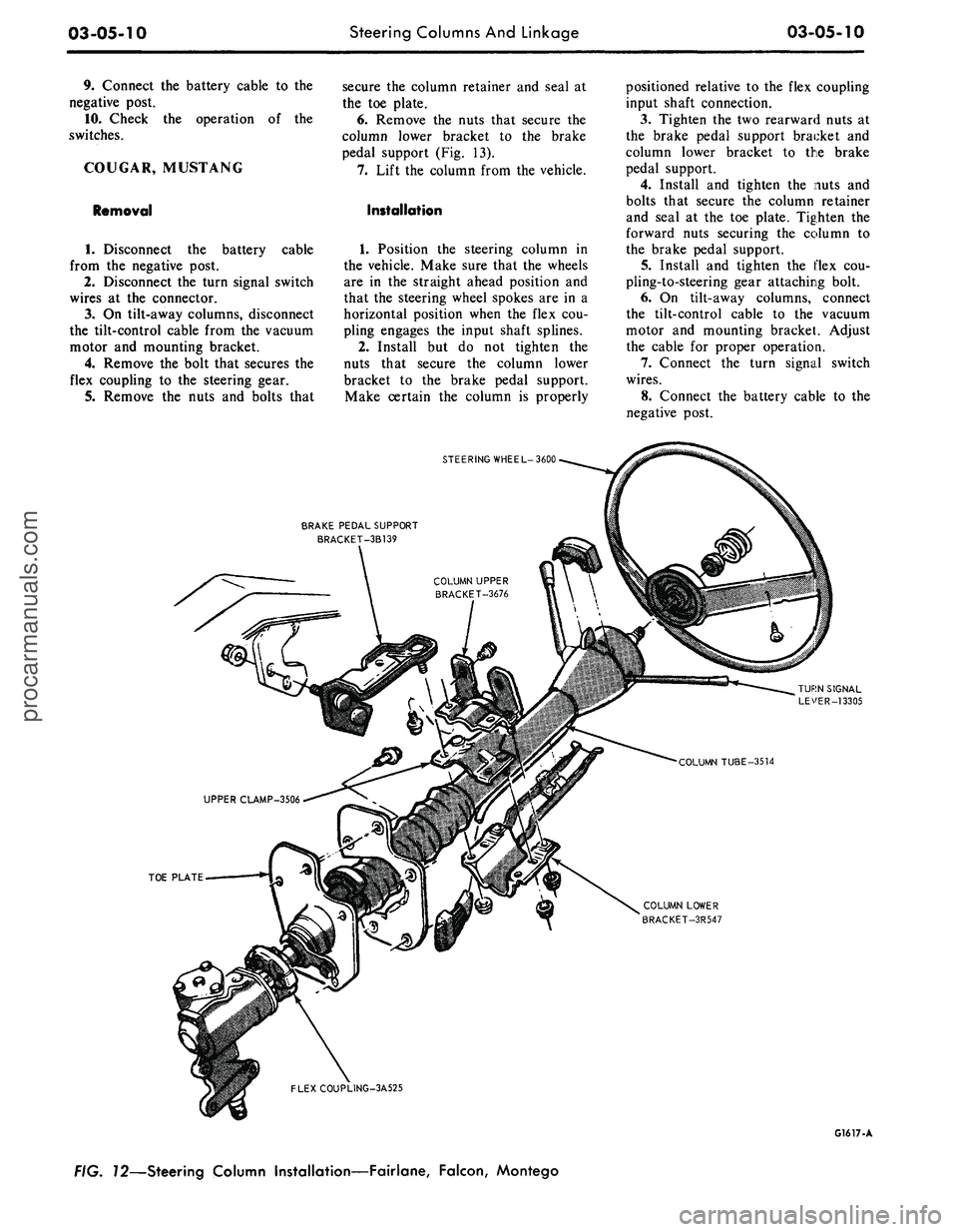
9. Connect the battery cable to the
negative post.
10.
Check the operation of the
switches.
COUGAR, MUSTANG
Removal
cable
1.
Disconnect the battery
from the negative post.
2.
Disconnect the turn signal switch
wires at the connector.
3.
On tilt-away columns, disconnect
the tilt-control cable from the vacuum
motor and mounting bracket.
4.
Remove the bolt that secures the
flex coupling to the steering gear.
5.
Remove the nuts and bolts that
secure the column retainer and seal at
the toe plate.
6. Remove the nuts that secure the
column lower bracket to the brake
pedal support (Fig. 13).
7.
Lift the column from the vehicle.
Installation
1.
Position the steering column in
the vehicle. Make sure that the wheels
are in the straight ahead position and
that the steering wheel spokes are in a
horizontal position when the flex cou-
pling engages the input shaft splines.
2.
Install but do not tighten the
nuts that secure the column lower
bracket to the brake pedal support.
Make certain the column is properly
positioned relative to the flex coupling
input shaft connection.
3.
Tighten the two rearward nuts at
the brake pedal support bracket and
column lower bracket to the brake
pedal support.
4.
Install and tighten the nuts and
bolts that secure the column retainer
and seal at the toe plate. Tighten the
forward nuts securing the column to
the brake pedal support.
5.
Install and tighten the flex cou-
pling-to-steering gear attaching bolt.
6. On tilt-away columns, connect
the tilt-control cable to the vacuum
motor and mounting bracket. Adjust
the cable for proper operation.
7.
Connect the turn signal switch
wires.
8. Connect the battery cable to the
negative post.
STEERING WHEEL-3600
BRAKE PEDAL SUPPORT
BRACKET-3B139
TOE PLATE
COLUMN LOWER
BRACKET-3R547
FLEXCOUPLING-3A525
G1617-A
FIG. 72—Steering Column Installation—Fairlane, Falcon, Montegoprocarmanuals.com
Page 133 of 413
03-05-20
Steering Columns And Linkage
03-05-20
placed if it becomes worn or damaged
(Figs.
18 through 21). Do not attempt
to straighten the sleeve if damaged.
1.
Remove the spindle connecting
rod end assemblies as described in the
previous sub-section.
2.
Screw the spindle rod end assem-
blies into the new sleeve the same
number of turns as the ends that were
removed. Do not tighten the clamp
bolts at this time.
3.
Position the sleeve and end as-
sembly on the center link and the
spindle arm. Install the attaching nut,
torque it to specification, and install
the cotter pin.
4.
Check and, if necessary, adjust
toe-in (Part 3-1). After toe-in is
checked and adjusted, oil the sleeve
clamp bolts then torque them to speci-
fication. The sleeve clamp must be in-
stalled as shown in Figs. 18 through
21.
CENTER LINK
REPLACEMENT
The center link connecting the Pit-
man arm and the idler arm is non-
adjustable and is provided with ta-
pered holes to accommodate the ball
studs (Figs. 18 through 21). The link
should be replaced when damaged or
when worn at the ball studs. On Lin-
coln Continental models, the link
should be replaced if excessive loose-
ness is noticed in either ball stud sock-
et.
REMOVAL
1.
Raise the vehicle on a hoist and
position safety stands.
2.
Remove the cotter pins and nuts
that attach both inner connecting rod
ends to the center link (Figs. 18
through 21).
3.
Disconnect the inner connecting
rod ends from the center link using
Tool 3290-C (Fig. 22).
4.
Remove the cotter pin and nut
attaching the idler arm to the center
link. Disconnect the idler arm from
the center link using Tool 3290-C for
Lincoln Continental models only.
5.
Remove the cotter pin and nut
attaching the Pitman arm to the cen-
ter link. Disconnect the Pitman arm
from the center link (use Tool 3290-C)
and remove the center link. On ve-
hicles equipped with the non-integral
power steering system, remove the
center link from the control valve as
detailed in Part 3-7.
INSTALLATION
1.
Replace the rubber seals on the
spindle connecting rod ends, if re-
quired.
2.
Position the center link to the
Pitman arm and idler arm and install
the attaching nuts loosely. On all ve-
hicles except Lincoln Continental
models, place the idler arm and the
front wheels in the straight ahead po-
sition to insure keeping the steering
wheel aligned and to prevent bushing
damage after the attaching nuts have
been torqued. On Lincoln Continental
models, insure that the seal is properly
installed on the center link. Torque
the nuts to the low end of the specifi-
cation. Continue to tighten each nut
until the slots in the nut align with the
hole in the stud. Then install a new
cotter pin.
3.
Position the spindle connecting
rod ends to the center link and install
the attaching nuts. Torque the nuts to
the low end of the specification. Con-
tinue to tighten each nut until the
slots in the nut align with the hole in
the stud. Then, install a new cotter
pin.
4.
Remove the safety stands, lower
the vehicle, check and adjust toe-in to
specification (Part 3-1).
STEERING IDLER ARM
AND BRACKET ASSEMBLY
REPLACEMENT
REMOVAL
If the idler arm bushings are worn
the complete idler arm assembly must
be replaced. In Lincoln Continental
models, if the socket at the idler
bracket is excessively loose, replace
the complet assembly.
1.
Remove the cotter pin and nut
attaching the steering center link at
the idler arm (Figs. 18 through 21).
2.
Disconnect the center link from
the idler arm (on Lincoln Continental
models, use Tool 3290-C).
3.
Remove the two bolts that attach
the idler arm and bracket assembly to
the frame.
INSTALLATION
1.
Secure the new idler arm and
bracket assembly to the frame with
the two attaching bolts (nuts and flat
washers as shown in Figs. 18, 19 and
21).
2.
On all vehicles except Lincoln
Continental models, place the idler
arm and the front wheels in the
straight ahead position to insure keep-
ing the steering wheel aligned and to
prevent bushing damage after the at-
taching nut has been torqued. Insert
the center link stud through the hole
in the end of the idler arm and install
the nut and washer.
On Lincoln Continental models, in-
sert the center link stud through the
hole in the end of the idler arm insur-
ing that the seal is properly installed
on the center link.
3.
Torque the idler arm rod nut to
specification and install a new cotter
pin.
PITMAN ARM
REPLACEMENT
REMOVAL
1.
Remove the cotter pin from the
castellated nut that attaches the steer-
ing center link to the Pitman arm.
Remove the castellated nut.
2.
Disconnect the steering center
link from the Pitman arm with tool
3290-C.
3.
Remove the Pitman arm attaching
nut and lock washer.
4.
Position the front wheels in the
straight ahead position. Remove the
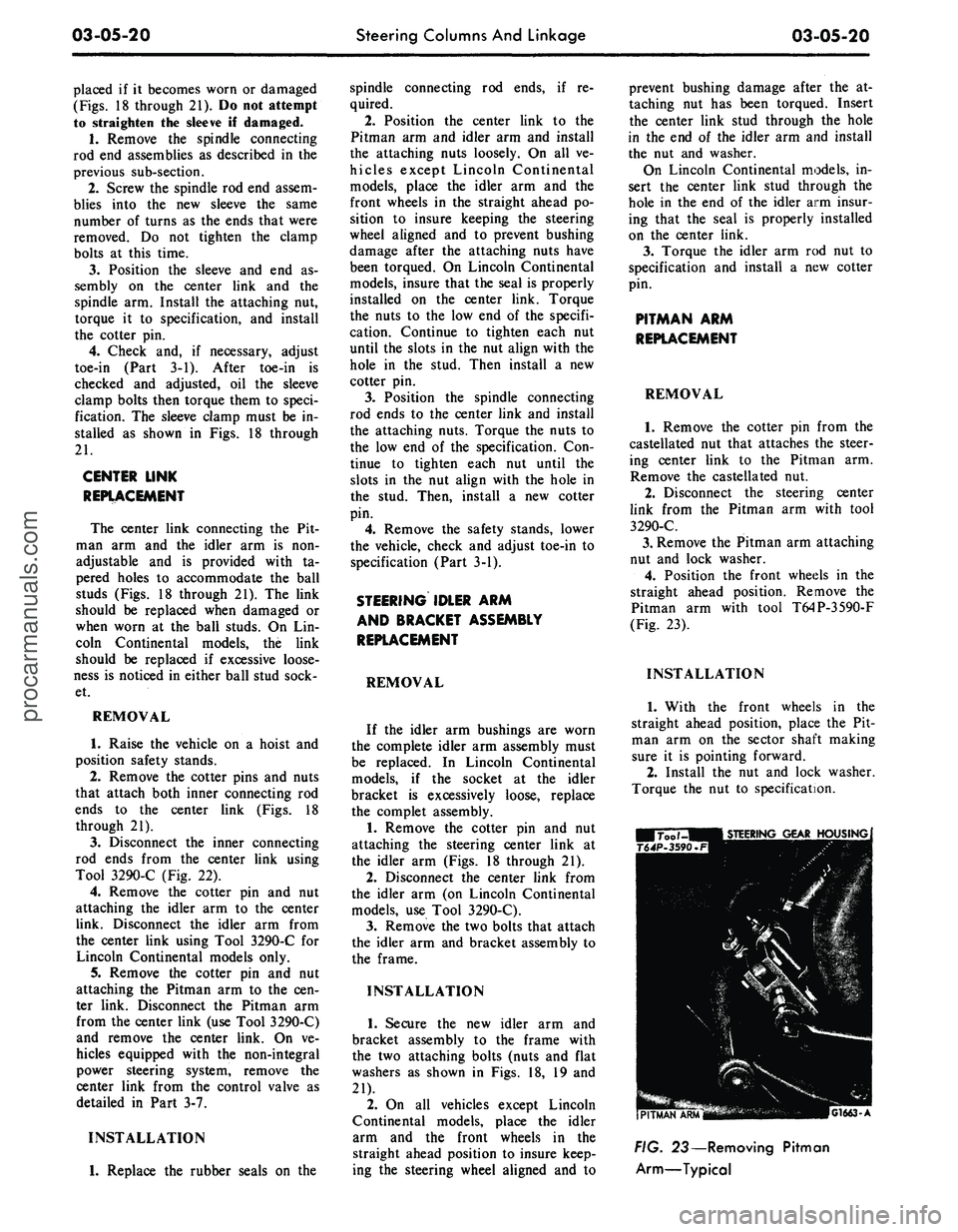
Pitman arm with tool T64P-3590-F
(Fig. 23).
INSTALLATION
1.
With the front wheels in the
straight ahead position, place the Pit-
man arm on the sector shaft making
sure it is pointing forward.
2.
Install the nut and lock washer.
Torque the nut to specification.
G1663-A
FIG. 23— Removing Pitman
Arm—Typicalprocarmanuals.com
Page 141 of 413
03-07-03
Ford Design Non-Integral Power Steering System
03-07-03
5.
Lower the vehicle and disconnect
the fluid return hose from the reser-
voir.
6. Disconnect the fluid pressure
hose from the pump outlet fitting.
7.
Remove 1 bolt attaching the
hoses,
insulator, and the retainer to
the frame side rail and remove the
hoses,
and the insulator and retainer
as an assembly from the vehicle.
8. Remove the pressure and return
hoses from the retainer and insulator.
INSTALLATION
1.
Install the pressure and return
hoses in the insulator and retainer.
Paint stripe on pressure hose must be
aligned with slot in insulator. Paint or
tape band on return hose must be cen-
tered in insulator. Position the assem-
bly to the frame side rail and install
the attaching bolt.
2.
Place a hose clamp on the fluid
return hose and install the hose on the
power steering pump reservoir return
fitting.
3.
Torque the pump outlet fitting to
specification (Part 3-13). Then, con-
nect the pressure hose to the outlet fit-
ting and torque the fitting to specifica-
tion.
4.
Raise the vehicle and connect the
pressure and return lines to the con-
trol valve.
5.
Install the clamp to retain the
hose tubes to the control valve.
6. Lower the vehicle and fill the
power steering pump reservoir with
fluid, C1AZ-19582-A, to the proper
level (Part 3-1).
7.
Start the engine and turn the
steering wheel to each end of its travel
several times to cycle the system.
Then, check for fluid leaks.
8. Stop the engine and again check
the power steering fluid level (Part
3-1). Add fluid as required.
REMOVAL AND INSTALLATION
HOISTING INSTRUCTIONS
Damage to suspension and/or steer-
ing linkage components may occur if
care is not exercised when positioning
the hoist adapters of 2 post hoists
prior to lifting the vehicle.
If a 2 post hoist is used to lift the
vehicle, place the adapters under the
front suspension lower arms. Do not
allow the adapters to contact the
steering linkage.
STEERING GEAR
Refer to Group 3-6, Section 3 for
detailed instructions.
POWER STEERING PUMP
Refer to Group 3-10, Section 3 for
detailed instructions.
POWER STEERING CONTROL
VALVE
REMOVAL
1.
Disconnect the 4 fluid line fit-
tings at the control valve, and drain
the fluid from the lines. Turn the front
wheels to the left and right several
times to force all the fluid from the
system.
2.
Loosen the clamping nut and
bolt at the right end of the sleeve.
3.
Remove the roll pin from the
steering arm-to-idler arm rod -through
the slot in the sleeve.
4.
Remove the control valve ball
stud nut.
5.
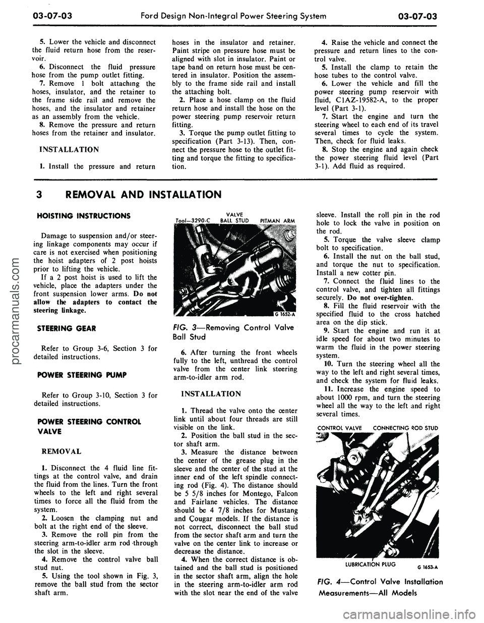
Using the tool shown in Fig. 3,
remove the ball stud from the sector
shaft arm.
VALVE
Too/-3290-C BALL STUD PITMAN ARM
FIG. 3—Removing Control Valve
Ball Stud
6. After turning the front wheels
fully to the left, unthread the control
valve from the center link steering
arm-to-idler arm rod.
INSTALLATION
1.
Thread the valve onto the center
link until about four threads are still
visible on the link.
2.
Position the ball stud in the sec-
tor shaft arm.
3.
Measure the distance between
the center of the grease plug in the
sleeve and the center of the stud at the
inner end of the left spindle connect-
ing rod (Fig. 4). The distance should
be 5 5/8 inches for Montego, Falcon
and Fairlane vehicles. The distance
should be 4 7/8 inches for Mustang
and Cougar models. If the distance is
not correct, disconnect the ball stud
from the sector shaft arm and turn the
valve on the center link to increase or
decrease the distance.
4.
When the correct distance is ob-
tained and the ball stud is positioned
in the sector shaft arm, align the hole
in the steering arm-to-idler arm rod
with the slot near the end of the valve
sleeve. Install the roll pin in the rod
hole to lock the valve in position on
the rod.
5.
Torque the valve sleeve clamp
bolt to specification.
6. Install the nut on the ball stud,
and torque the nut to specification.
Install a new cotter pin.
7.
Connect the fluid lines to the
control valve, and tighten all fittings
securely. Do not over-tighten.
8. Fill the fluid reservoir with the
specified fluid to the cross hatched
area on the dip stick.
9. Start the engine and run it at
idle speed for about two minutes to
warm the fluid in the power steering
system.
10.
Turn the steering wheel all the
way to the left and right several times,
and check the system for fluid leaks.
11.
Increase the engine speed to
about 1000 rpm, and turn the steering
wheel all the way to the left and right
several times.
CONTROL VALVE CONNECTING ROD STUD
LUBRICATION PLUG
G1653-A
FIG. 4—Control Valve Installation
Measurements—All Modelsprocarmanuals.com
Page 142 of 413
03-07-04
Ford Design Non-Integral Power Steering System
03-07-04
12.
Stop the engine, and check the
control valve and hose connections for
fluid leaks. Correct the cause of any
leaks.
13.
Check the fluid level, and refill
the reservoir if necessary.
14.
With the engine running check
the position of the steering wheel
when the front wheels are in the
straight-ahead position.Do not make
any adjustments until toe-in is
checked.
15.
Keep the engine running, and
check toe-in. If either toe-in or steer-
ing wheel position is not correct make
all necessary adjustments (Part 3-1) at
the spindle connecting rod sleeves.
16.
Check the effort to turn the
wheels in both directions. The effort
should be about equal in both direc-
tions.
POWER CYLINDER
REMOVAL
1.
Disconnect the two fluid lines
from the power cylinder and allow
them to drain into a container.
CENTER LINK
POWER CYLINDER
Tool- T64P-3590-F
G 1654-A
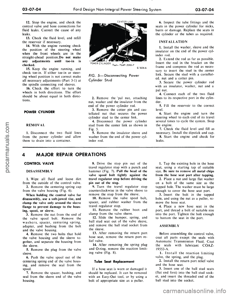
FIG. 5—Disconnecting Power
Cylinder Stud
2.
Remove the 'pal nut, attaching
nut, washer and the insulator from the
end of the power cylinder rod.
3.
Remove the cotter pin and cas-
tellated nut that secures the power
cylinder stud to the center link.
4.
Disconnect the power cylinder
stud from the center link as shown in
Fig. 5.
5.
Remove the insulator sleeve and
washer from the end of the power cyl-
inder rod.
6. Inspect the tube fittings and the
seats in the power cylinder for nicks,
burrs or damage. Replace the seats in
the cylinder or the tubes as required.
INSTALLATION
1.
Install the washer, sleeve and the
insulator on the end of the power cyl-
inder rod.
2.
Extend the rod as far as possible.
Insert the rod in the bracket on the
frame and compress the rod as neces-
sary to insert the stud in the -center
link. Secure the stud with a castellat-
ed, nut and a cotter pin.
3.
Secure the power cylinder rod
with an insulator, washer, nut and a
pal nut.
4.
Connect each of the two fluid
lines to its respective port in the cylin-
der.
5.
Fill the reservoir to the correct
level.
6. Start the engine and turn the
steering wheel to each end of its travel
several times to cycle the system. Stop
the engine.
7.
Check the fluid level and fill as
necessary. Install the dipstick and cap.
8. Start the engine and check for
leaks.
MAJOR REPAIR OPERATIONS
CONTROL VALVE
DISASSEMBLY
1.
Wipe all fluid and loose dirt
from the outside of the control valve.
2.
Remove the centering spring cap
from the valve housing (Fig. 6).
When holding the control valve for
disassembly, use a soft-jawed vise, and
clamp the valve only around the sleeve
flange to prevent damage to the hous-
ing, spool, or sleeve.
3.
Remove the nut from the end of
the valve spool bolt. Remove the
washers, spacer, centering spring,
adapter, and bushing from the bolt
and the valve housing.
4.
Remove the two bolts that hold
the valve housing and the sleeve to-
gether, and separate the housing from
the sleeve.
5.
Remove the plug from the valve
sleeve.
6. Push the valve spool out of the
centering spring end of the valve hous-
ing, and remove the seal from the
spool.
7.
Remove the spacer, bushing, and
seal from the sleeve end of the valve
housing.
8. Drive the stop pin out of the
travel regulator stop with a punch and
hammer (Fig. 7). Pull the head of the
valve spool bolt tightly against the
travel regulator stop before driving the
pin out of the stop.
9. Turn the travel regulator stop
counterclockwise in the valve sleeve to
remove the stop from the sleeve.
10.
Remove the valve spool bolt,
spacer, and rubber washer from the
travel regulator stop.
11.
Remove the rubber boot and
clamp from the valve sleeve.
12.
Slide the bumper, spring, and
ball stud seat out of the valve sleeve,
and remove the ball stud socket from
the sleeve.
13.
After removing the return port
hose seat, remove the return port re-
lief valve.
14.
After removing the spring plug
and O-ring, remove the reaction limit-
ing valve (Fig. 8).
Tube Seat Replacement
If a hose seat is worn or damaged it
should be replaced. It can be removed
with an Easy-Out tool, or by using a
bolt of appropriate size as a puller.
1.
Tap the existing hole in the hose
seat, using a starting tap of suitable
size.
Be sure to remove all metal chips
from the hose seat port after tapping.
2.
Place a nut and large flat washer
on a bolt of the same size as the
tapped hole. The washer must be large
enough to cover the hose seat port.
3.
Insert the bolt in the tapped
hole,
and using the nut as a puller, re-
move the hose seat.
4.
Place a new hose seat in the
port, and thread a bolt of suitable size
into the port. Tighten the bolt enough
to bottom the seat in the port.
ASSEMBLY
Before assembling the control valve,
coat all parts except the seals with
Automatic Transmission Fluid. Coat
the seals with lubricant COAZ-
19553-A.
1.
Install the reaction limiting
valve, the spring, and the plug.
2.
Install the return port relief valve
and the hose seat.
3.
Insert one of the ball stud seats
(flat end first) into the ball stud sock-
et, and insert the threaded end of the
ball stud into the socket.procarmanuals.com