Page 103 of 136
Bod
Work
Adjusting
Hood
Lock
Control
Lever
Operating
Force
When
the
control
lever
operatmg
force
IS
ex
ceSSlve
loosen
the
dove
tail
bolt
retammg
nut
2
Increase
dove
tall
bolt
1
mstalled
length
and
reduce
tensIOn
of
the
spring
Tightening
torque
Dove
tall
bolt
retaining
nut
108
to
18
1
ft
lb
Fig
166
Removing
male
Side
of
the
hood
lock
DovetaIl
bolt
lock
nut
Ttghtenlllg
torque
1
5
to
2
5
kg
m
1108
to
18
1
It
Ib
FIg
167
Removing
female
Side
ofthe
hood
lock
FIg
169
Section
view
of
hood
lock
2
10
6
mm
0079
10
0
236
on
Fig
168
Removing
hood
lock
control
lever
Fig
170
Checking
free
play
of
hood
panel
U3
Page 104 of 136

Bod
Work
J
G
3
1
7
iJ
0
t
Fig
171
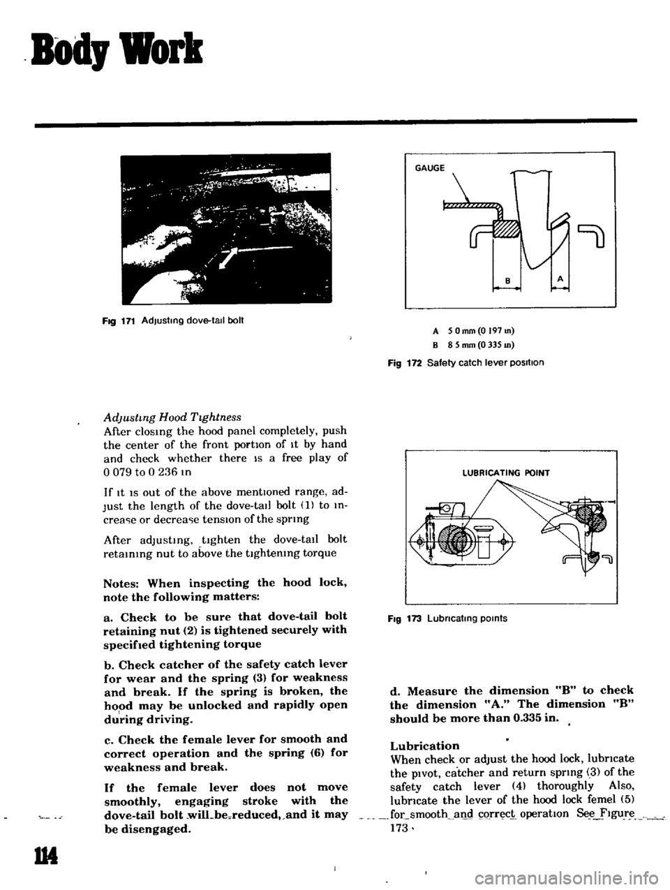
Adjusting
dove
tall
boll
AdJustmg
Hood
TIghtness
After
clOSIng
the
hood
panel
completely
push
the
center
of
the
front
portIon
of
It
by
hand
and
check
whether
there
IS
a
free
play
of
o
079
to
0
236
In
If
It
IS
out
of
the
above
mentIOned
range
ad
Just
the
length
of
the
dove
tall
bolt
1
to
In
crea
ie
or
decrea
ie
tensIOn
of
the
sprIng
After
adJustIng
tighten
the
dove
tall
bolt
retaInIng
nut
to
above
the
tIghtenIng
torque
Notes
When
inspecting
the
hood
lock
note
the
following
matters
a
Check
to
be
sure
that
dove
tail
bolt
retaining
nut
2
is
tightened
securely
with
specifIed
tightening
torque
b
Check
catcher
of
the
safety
catch
lever
for
wear
and
the
spring
3
for
weakness
and
break
If
the
spring
is
broken
the
hood
may
be
unlocked
and
rapidly
open
du
ring
driving
c
Check
the
female
lever
for
smooth
and
correct
operation
and
the
spring
6
for
weakness
and
break
If
the
female
lever
does
not
move
smoothly
engaging
stroke
with
the
dove
tail
bolt
wilLbeoreduced
and
it
may
be
disengaged
1M
9
A
5
Omm
O
197
m
B
8
5
mm
0
335
m
Fig
172
Safety
catch
lever
positIOn
LUBRICATING
POINT
Fig
173
Lubncatlng
POints
d
Measure
the
dimension
8
to
check
the
dimension
A
The
dimension
8
should
be
more
than
0
335
in
Lubrication
When
check
or
adjust
the
hood
lock
lubricate
the
pIvOt
catcher
and
return
sprIng
3
of
the
safety
catch
lever
4
thoroughly
Also
lubricate
the
lever
of
the
hood
lock
femel
5
focsmooth
all
c1
orr
i
operatIon
Se
ylgur
173
Page 106 of 136

Bod
Work
TRUNK
LID
LOCK
Removal
Loosen
m
tallatlOn
bolts
and
remove
the
tl
Iker
and
lock
from
the
body
Remove
the
leaf
chp
lu
ed
to
secure
the
trunk
hd
lock
cylmder
on
the
body
and
remove
the
trunk
lId
lock
cylIndCl
Adjustment
Sedan
When
adjustmg
engagement
between
the
lock
and
tnker
set
the
lock
statlOnanly
and
properly
adjust
stnker
poSitIOn
Adjustmg
stroke
toward
left
and
nght
SIdes
dIrectIOn
IS
0
890
m
and
03150
m
toward
vertical
dIrectIOn
VAN
j
1
II
U8
Coupe
When
adju
tmg
engagement
between
the
lock
and
stnker
adjust
stnker
poSitIOn
toward
left
and
right
Sides
adju
tmg
stroke
02362
m
and
lock
pOSitIOn
for
vertical
directIOn
ad
justmg
stroke
03
50
m
Tlghtemng
torque
Lock
and
stnker
fixmg
bolt
o
87
to
45
ft
lb
TRUNK
LID
TORSION
BAR
The
procedures
of
m
tallIng
torsIOn
bar
are
mdlcated
as
follows
Note
When
installing
the
torsion
bar
u
te
a
torsIOn
bar
wrench
J
tl
l
11
4
i
0
t
b
f
I
Back
door
hUlle
tomon
bOT
2
BlCk
door
hmge
3
Back
door
4
Back
door
lock
rod
l
Lock
6
Stnker
7
Stnker
shun
8
Back
door
side
dovetad
9
Side
dovetl1l
tllm
10
Back
door
bumper
II
Back
door
bumper
plate
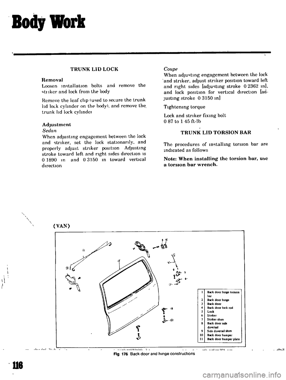
Ag
176
Back
door
and
hinge
constructions
Page 120 of 136

Specifications
SERVICE
DATA
AND
SPECIFICATIONS
1
vpc
RCl
n
ulatlllg
bdll
type
ClrrJtm
Ieertng
wheel
dldl1lCler
Od
JpJuty
iteenng
angle
IImer
wheel
outer
heel
PIdY
Ieermg
wheel
tJJ
d
ud
thl
kness
of
worm
beaTIng
shulls
hllttal
turnmg
torque
of
column
assembly
le
Hance
uf
ddJustmg
SLrew
to
sedor
shaft
Length
of
side
rod
TlghteolOg
torque
Steenng
wheellol
k
nul
Steenng
po
t
d
unp
to
steermg
pO
1
hr
H
lct
holts
llIlJp
ihlc
C
lrtng
llImn
hole
over
hnlt
IllImn
10
L
If
hOUI
IIl
holts
tdt
t
f
III
ge
lf
hou
lIl
holh
dlu
m
l
rew
m
nut
edM
h
If
I
10
plllllJIl
drill
nut
If
hOll
lI1g
In
Side
I1MIIl
bar
holt
Jlld
nut
Idler
dflll
nul
Idler
arm
to
stde
l1lJlO
bar
bolts
Jnd
nuts
B
III
stud
nuts
51dc
rod
hJf
IOl
k
nuts
mm
m
15
I
400
7
024
1
211
L
US
pI
Imp
pt
43
1
16
111111
111
20
to
2
10
7X7
to
0
JX4
mm
m
OS
0
0197
kg
cm
lIl
oz
2
0
to
5
0
27
X
10
69
4
mm
m
005
0
0020
296
8
1169
nun
Ill
kg
Ill
ft
Ihl
3
0
10
3
5
I
7
10
2
S
1
kg
m
ft
Ih
kg
Ill
ft
Ih
kg
Ill
I
ft
Ih
kg
Ill
ft
Ib
kg
Ill
ft
Ih
kg
m
ft
Ih
kg
m
ft
Ih
08
to
I
0
5
8
107
15
to
18
108
to
13
I
o
8
10
I
0
S
X
to
7
I
1
5
to
2
5
10810
18
I
7
10
2
8
12
3
10
20
2
201030
14510217
14
101
kg
Ill
ft
Ib
kg
mltt
Ih
I
9
to
2
6
13
7
to
18
8
5
7
106
3
4
2
1045
6
kg
m
ft
Ib
kg
m
ft
Ib
kg
Ill
ft
Ih
191026
13710188
30
to
0
21
7
to
36
2
XOlo
100
57810723
I3l
Page 121 of 136
Specifications
SERVICE
DATA
Valve
clearJnce
IHot
mm
In
mm
In
mm
In
kg
Ib
Intdke
exhaust
Fan
belt
tensIOn
Tlghtemng
torque
Cold
Cyhnder
head
bolts
kg
m
ft
Ib
1st
turn
2nd
turn
Re
l1ghtemng
torque
Hot
Mamfold
nuts
Carburetor
nuts
Spark
plugs
ad
capacIty
of
engine
including
od
filter
Maximum
L
US
gal
Imp
gal
L
US
gal
Imp
gal
Mmlmum
Water
capacity
of
coohng
system
Wllhout
heater
L
US
gal
Imp
gal
W
th
heater
L
US
gal
Imp
gal
CompressIOn
pressure
at
rpm
kg
cm2
PSI
Battery
specific
gravity
FrigId
climates
Tropical
clImates
Other
climates
132
Permlsslble
value
rlver
I
22
Over
118
Over
I
20
035
0014
035
0014
10
to
15
0
394
to
0
591
10
22
40
to
4
5
29
to
33
5
5
to
6
0
40
to
43
60
to
6
5
43
to
47
09toI4
65toI0
o
5
to
I
0
3
6
to
7
2
I
5
to
2
0
II
to
14
33
l
2
3
10
42
Ji
49
1
4
IJi
125
to
145
78
to
206
350
Fully
charged
value
at
20
C
68
F
128
123
126
Page 123 of 136
Specifications
ENGINE
GENERAL
SPECIFICATION
Cylinder
Jrrangement
4mlme
Displacement
ce
eu
m
71
71
5
Bore
and
stroke
mm
m
73
x
70
2
874
x
2
756
Valve
arrangement
Over
head
vdlve
Fmng
order
I
3
42
Engine
Idle
rpm
800
Manual
transmiSSIOn
650m
D
Automatic
transrmsslon
Compresc
lon
ratio
85
011
pressure
Hol
al
2
000
rpm
kg
em
Ib
sq
m
3
0
to
3
5
43
10
50
TIGHTENING
TORQUE
Uml
kg
m
ft
Ib
Cyhnder
head
bolts
5
5
10
6
0
40
10
43
3
2
to
3
8
2310
28
CQnnedmg
rod
nuts
Flywheel
bolls
651075
471054
Main
bearing
cap
bolts
5
0
10
6
0
36
to
43
4
0
10
4
8
29
10
35
o
4
to
0
6
2
9
1043
Camshaft
gear
bolts
011
pan
bolts
Ot
pump
bolts
1
I
to
I
7
8
0
10
12
o
9
to
I
4
65
to
lO
J5
to
16
108
to
116
011
stramer
bolts
Crank
pulley
bolts
134
Page 129 of 136
Specifications
SPECIFICATIONS
AND
SERVICE
DATA
Make
NGK
Model
BP5ES
HITACHI
l46PW
S
ze
Screw
dla
x
Reach
mm
m
14
x
19
0
55
x
0
75
o
8
to
0
9
0
031
10
0
035
15t025
11
Oto
150
Plug
gap
mm
10
Tlghtemng
torque
kg
m
ft
lb
FUEL
SYSTEM
Carburetor
model
DCH3064
for
ManuallransrnlSSlon
DCH306
5
for
Automalle
transmisSIon
Downdraft
Apphed
englOe
Type
Primary
Secondary
Outlet
dIameter
10m
10
10m
10
26
J
024
30
1
181
20
0
787
26
I
024
95
140
fI
80
fI
80
fI
43
fI
50
Venturi
diameter
MamJet
MalO
air
bleed
Slow
let
Slow
alf
bleed
215
100
Power
Jet
Float
level
H
mm
lO
60
18
to
20
0
709
to
0
748
HO
Page 131 of 136
Specifications
STARTER
Make
and
type
Nommal
output
System
voltage
Weight
KW
V
J
Mdnual
Au
tOP1allc
T
ransmJ
lJSJon
TransmJsslon
HITACHI
S114
87M
HITACHI
S
114
I
S6
10
10
12
12
46
10
I
S
4
119
12
12
less
than
60
less
than
60
more
than
7
000
more
than
6
000
63
63
less
than
420
less
than
420
more
than
0
9
6
S
mare
than
1
0
7
2
MagnetiC
shift
MagnetiC
shift
9
9
kg
Ib
No
load
Tennmal
voltage
V
Current
A
RevolutIon
rpm
Load
Tennmal
voltage
Current
Torque
V
A
kg
m
ft
Ib
Sluftmg
type
of
pmlOn
gear
Number
of
teeth
on
pinion
gear
142
Page:
< prev 1-8 9-16 17-24