1969 DATSUN B110 torque
[x] Cancel search: torquePage 31 of 136
BDgiDe
TIghtening
torque
40
to
43
ft
Ib
Install
the
push
rod
Install
the
rocker
haft
assembly
and
tighten
the
I
ocker
haft
bracket
bolts
to
the
specIfied
torque
Tightening
torque
15
to
18
ft
lb
Note
TIghtening
operation
should
be
made
gradually
10
separating
two
or
three
stages
and
outwardly
from
the
center
bracket
In
tall
the
Intake
and
exhaust
mamfolds
TIghtening
torque
65
to
10
ft
lb
AdJu
t
valve
clemance
wIth
the
specIfied
dlmenblOn
Install
the
rocker
cover
and
carburetor
assem
bly
I
n
tdll
the
watel
pump
and
thermostat
Tlghtemng
tOl
que
65
to
10
ft
lb
I
nstall
the
crankshaft
pulley
Tighten
the
crank
pulley
bolt
to
the
specIfied
torque
TIghtenIng
torque
109
to
116
ft
lb
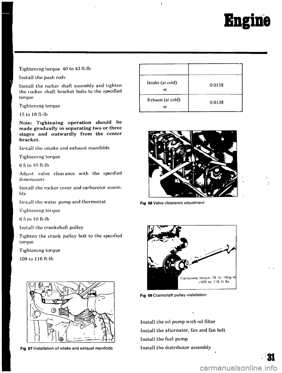
Fig
67
Installation
of
Intake
and
exhaust
manifolds
Intake
at
cold
00138
In
Exhaust
at
cold
00138
In
Fig
68
Valve
clearance
adjustment
TlqhtCnlnq
torque
15
to
16kg
m
109
to
116ltlb
Fig
69
Crankshaft
pulley
installation
Install
the
at
pump
with
011
filter
Install
the
alternator
fan
and
fan
belt
Install
the
fuel
pump
Install
the
dlstnbutor
assembly
31
Page 45 of 136
Icnition
Sptem
Ovcrhc
Jtmg
Norm
Jl
i
r
rJ
I
ttr
I
i
V
Carbon
fould
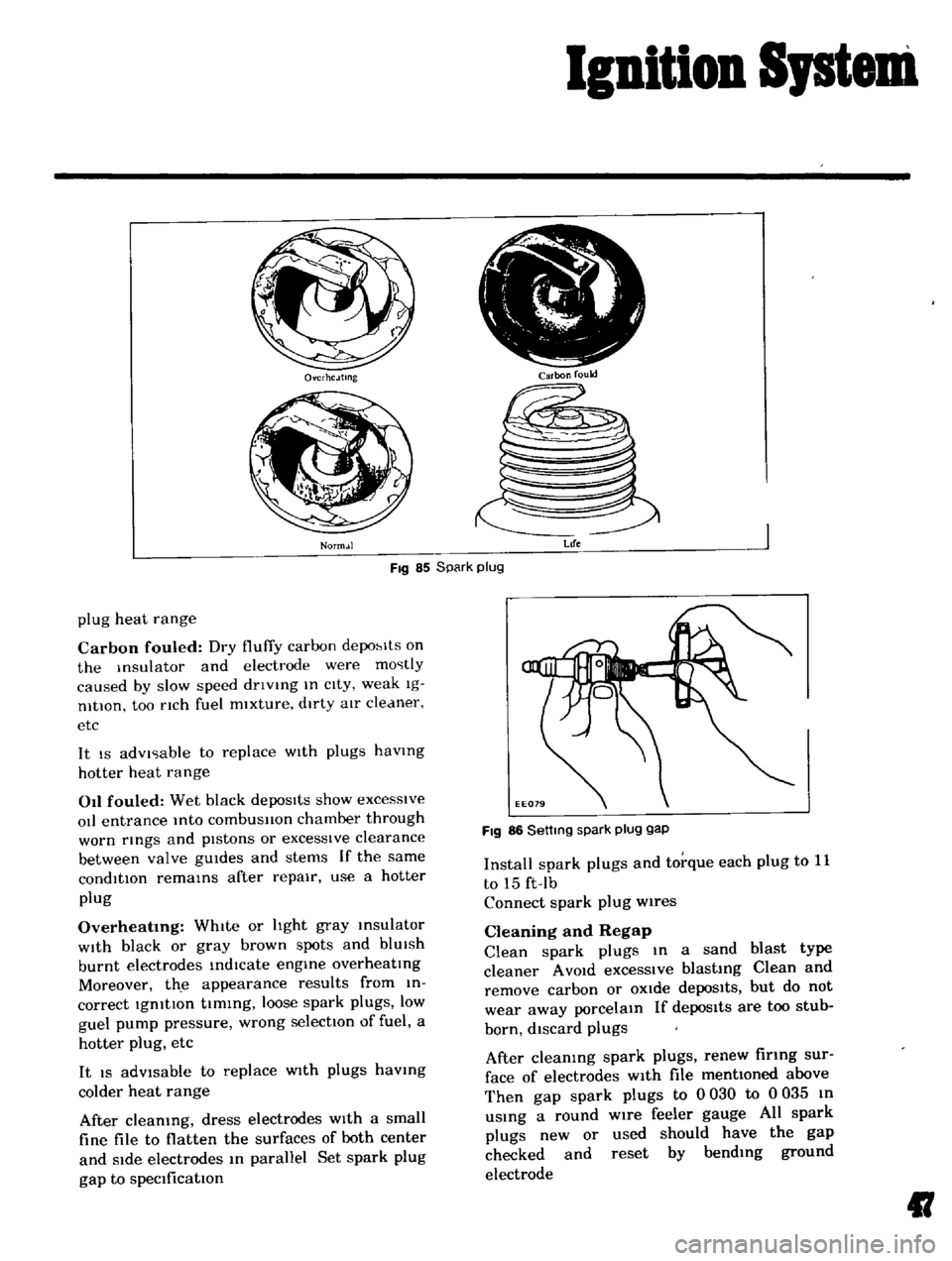
Fig
85
Spark
plug
Life
plug
heat
range
Carbon
fouled
Dry
fluffy
carbon
depo
lts
on
the
Insulator
and
electrode
were
mostly
caused
by
slow
speed
dnvlng
In
cIty
weak
Ig
nltlOn
too
nch
fuel
mixture
dirty
aIr
cleaner
etc
It
IS
advIsable
to
replace
WIth
plugs
havmg
hotter
heat
range
011
fouled
Wet
black
depoSits
show
excesSive
oIl
entrance
Into
combusllon
chamber
through
worn
rmgs
and
pIstons
or
excessIve
clearance
between
valve
gUIdes
and
stems
If
the
same
condition
remams
after
repair
use
a
hotter
plug
Overheatmg
WhIte
or
hght
gray
msulator
WIth
black
or
gray
brown
spots
and
blUIsh
burnt
electrodes
indIcate
engme
overheatIng
Moreover
th
e
appearance
results
from
in
correct
IgnitIon
tIming
loose
spark
plugs
low
guel
pump
pressure
wrong
selectIOn
of
fuel
a
hotter
plug
etc
It
IS
adVisable
to
replace
WIth
plugs
havmg
colder
heat
range
After
cleaning
dress
electrodes
With
a
small
fine
file
to
flatten
the
surfaces
of
both
center
and
Side
electrodes
In
parallel
Set
spark
plug
gap
to
specification
FIg
86
Settmg
spark
plug
gap
Install
spark
plugs
and
torque
each
plug
to
11
to
15
ft
Ib
Connect
spark
plug
wires
Cleaning
and
Regap
Clean
spark
plugs
In
a
sand
blast
type
cleaner
A
VOId
excessIve
blasting
Clean
and
remove
carbon
or
OXide
depoSits
but
do
not
wear
away
porcelain
If
depos1ts
are
too
stub
born
discard
plugs
After
cleaning
spark
plugs
renew
firing
sur
face
of
electrodes
With
file
mentioned
above
Then
gap
spark
plugs
to
0
030
to
0
035
In
uSing
a
round
wire
feeler
gauge
All
spark
plugs
new
or
used
should
have
the
gap
checked
and
reset
by
bending
ground
electrode
II
Page 68 of 136
Brakes
Note
Be
careful
not
to
confuse
the
piston
A
with
B
Apply
rubber
grease
hghtly
to
the
shdlng
par
tlon
of
p1ston
and
Insert
the
piston
Into
the
cyhnder
Note
When
insertmg
the
piston
be
careful
not
to
insert
too
far
Install
the
boot
and
retaining
nng
Install
so
that
the
yoke
groove
of
bIas
nng
of
piston
A
COinCide
wIth
the
yoke
groove
of
cyhnder
YOKE
SPRING
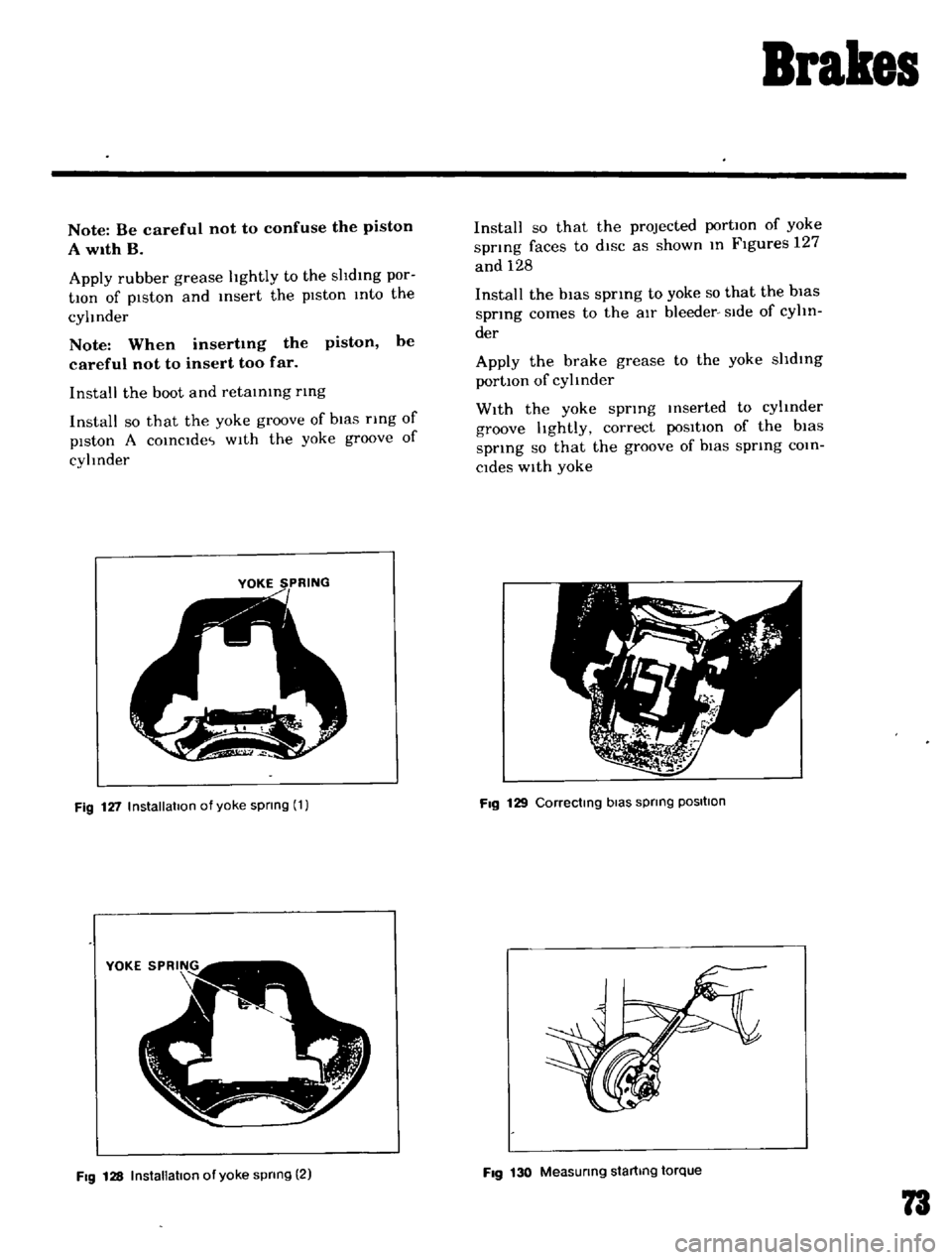
Fig
127
Installation
of
yoke
spnng
1
Fig
128
InstallatIOn
of
yoke
spnng
2
Install
so
that
the
projected
portIOn
of
yoke
spnng
faces
to
diSC
as
shown
In
Figures
127
and
128
Install
the
bias
spring
to
yoke
so
that
the
bias
spring
comes
to
the
aIr
bleeder
Side
of
cyhn
der
Apply
the
brake
grease
to
the
yoke
shdlng
portIOn
of
cylinder
With
the
yoke
spring
Inserted
to
cylinder
groove
hghtly
correct
poSitIOn
of
the
bias
spnng
so
that
the
groove
of
biaS
spring
COin
Cides
With
yoke
Fig
129
Correctmg
bias
spnng
POSItion
Fig
130
Measunng
startmg
torque
73
Page 69 of 136
Brakes
c
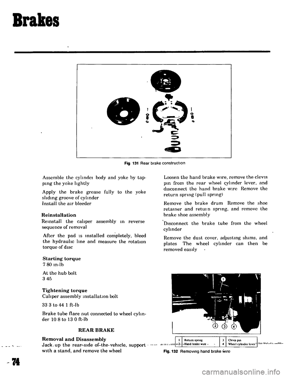
Fig
131
Rear
brake
construction
Assemble
the
cylIndel
body
and
yoke
by
tap
ping
the
yoke
lIghtly
Apply
the
brake
grease
fully
to
the
yoke
slIding
groove
of
cylInder
I
nstall
the
air
bleeder
Reinstallation
Reinstall
the
calIper
assembly
In
reverse
sequence
of
removal
After
the
pad
IS
Installed
completely
bleed
the
hydraulIc
line
and
measure
the
rotatton
torque
of
diSC
Starting
torque
780
In
Ib
At
the
hub
bolt
345
Tightening
torque
CalIper
assembly
installatIOn
bolt
33
3
to
44
1
ft
lb
Brake
tube
flare
nut
connected
to
wheel
cylIn
der
108
to
13
0
ft
lb
REAR
BRAKE
Removal
and
Disassembly
Jack
up
the
rear
slde
of
the
vehicle
support
With
a
stand
and
remove
the
wheel
74
Loosen
the
hand
brake
Wire
remove
the
cleVIS
pin
from
the
rear
wheel
l
ylInder
lever
and
disconnect
the
hand
brake
wIre
Remove
the
return
spnng
pull
spnng
Remove
the
brake
drum
Remove
the
shoe
retainer
and
retUl
n
spnng
and
remove
the
brake
shoe
assembly
DIsconnect
the
brake
tube
from
the
wheel
cylinder
Remove
the
dust
cover
adjusting
shims
and
plates
The
wheel
cylInder
can
then
be
removed
eaSily
Flg
132
RemOVing
hand
brake
vme
Page 85 of 136
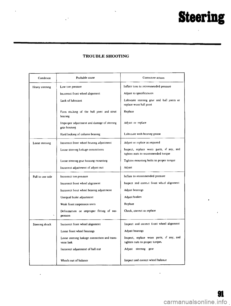
SteeriDg
ConditIon
lIeavy
steering
Loose
steenng
Pull
to
one
side
Steermg
shock
TROUBLE
SHOOTING
Probable
cause
Low
tIre
pressure
In
orreet
front
wheel
altgnmcnt
Lack
of
lubricant
FITm
stll
kmg
of
the
ball
Jomt
and
strut
beanog
Improper
adjustment
and
damage
of
steering
gcar
housmg
H
Hd
lock1l1g
of
column
beanng
Incorrect
front
wheel
be
mng
ddJustment
Loose
steermg
hnkJge
connectIOns
Loose
steermg
gCdf
housmg
mountIng
Incorrect
adjustment
of
ddJust
nut
Incorrect
lITe
pre
sure
Incorrect
front
wheel
dhgnment
Incorrect
front
wheel
beanng
adjustment
Unequal
brdke
ddJustment
Weak
front
suspensIOn
umts
Deformation
or
Improper
fittmg
of
sus
pensIOn
Incorrect
front
wheel
ahgnment
Loose
front
wheel
beanngs
Loose
steering
lmkage
connectIOn
and
trans
verse
lmk
Incorrect
adjustment
of
ball
nut
Wheels
out
of
balance
Corrective
action
Innate
tires
to
recommended
pressure
Adjust
to
speclficatJono
Lubricate
steering
gc
H
and
b
dl
jomts
or
replace
WOln
bdll
jomt
Replace
Adjust
or
repldce
LubrlcJte
with
bearing
grease
Adjust
or
replace
as
reqUired
Inspect
replace
worn
pdrts
If
any
and
tighten
nuts
to
recommended
torque
TIghten
mountmg
bolts
to
proper
torque
Adjust
Inflate
to
recommended
pressurc
Inspect
and
corred
front
WhlCI
alignment
Adjust
bearings
Adjust
brakes
Replace
Check
correct
or
replace
Inspect
and
correct
front
wheel
alIgnment
Adjust
bearings
Inspect
replace
worn
parts
If
any
and
tighten
nuts
to
proper
torque
Adjust
steenng
gear
Inspect
and
correct
wheel
balanl
e
81
Page 88 of 136
Bear
Drive
Suspension
A
correct
contact
pattern
means
that
It
beii
the
ange
of
2
3
to
3
4
from
the
tip
of
the
tooth
nder
no
load
Backlash
IS
010
to
015mm
00039
to
00059
n
Tlghtemng
torque
of
drlve
gear
bolt
60
to
70
kg
m
434
to
506
ft
Ibl
TIghten
by
tapping
bolt
head
with
a
0
lkg
1
4
lb
hammer
TIghtening
torque
of
dnvt
pmlon
nut
12
to
11
kg
m
86
8
to
1229
ft
lb
Plmon
be
nng
adjust
spacer
O
lve
plmon
adlustlng
washer
T
W
N
HxO
011
0
2
mml
T
T
Drive
gear
ad
ustlng
shims
Left
Ide
T1
jA
C
0
H
I
001
0200
E
lmml
Right
SIde
T2
B
D
HI
001
0
200
F
mml
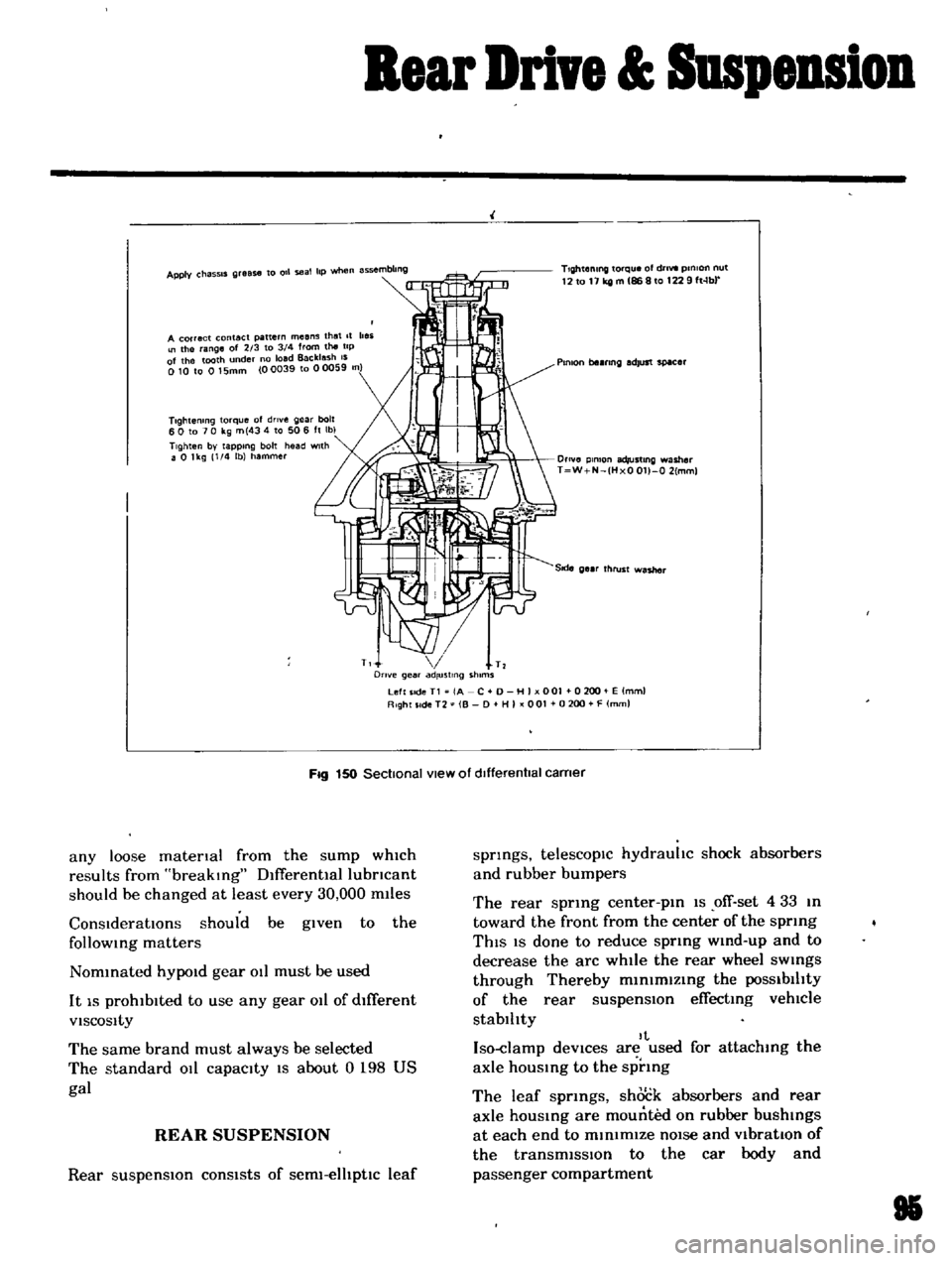
Fig
150
Sectional
view
of
dIfferentIal
carner
any
loose
matenal
from
the
sump
which
results
from
breaking
Dlfferentlallubncant
should
be
changed
at
least
every
30
000
m11es
ConsIderatIOns
should
be
given
to
the
follOWing
matters
Nommated
hYPOld
gear
011
must
be
used
It
IS
prohibited
to
use
any
gear
011
of
dIfferent
VISCOSity
The
same
brand
must
always
be
selected
The
standard
011
capacity
IS
about
0
198
US
gal
REAR
SUSPENSION
Rear
suspensIOn
consists
of
serm
elhptlc
leaf
springs
telescopIc
hydrauhc
shock
absorbers
and
rubber
bumpers
The
rear
sprmg
center
pm
1S
ofT
set
4
33
m
toward
the
front
from
the
center
of
the
sprmg
ThIS
IS
done
to
reduce
sprmg
wmd
up
and
to
decrease
the
arc
while
the
rear
wheel
sWings
through
Thereby
m1n1mlzmg
the
POSSibilIty
of
the
rear
suspensIOn
effecting
vehlCle
stablhty
It
Iso
damp
deVices
are
used
for
attachmg
the
axle
hOUSing
to
the
sprmg
The
leaf
sprmgs
shock
absorbers
and
rear
axle
housmg
are
mounted
on
rubber
bushings
at
each
end
to
minimIZe
nOIse
and
VibratIOn
of
the
transmiSSIon
to
the
car
body
and
passenger
compartment
85
Page 91 of 136
Clutch
DESCRIPTION
The
clutch
IS
a
sIngle
dry
dIsc
diaphragm
prIng
type
clutch
The
major
components
are
clutch
cover
pressure
plate
diaphragm
sprIng
and
wire
rIngs
The
clutch
diSC
IS
provided
WIth
rIveted
plates
on
both
surfaces
and
cot
bprIngs
arranged
In
a
hnk
The
COIl
prIngs
absOl
b
shock
whIle
engagIng
the
clutch
softemng
and
smoothIng
clutch
engagement
Release
bearIng
sleeve
and
WIthdrawal
lever
dre
used
to
control
clutch
engagement
and
disengagement
Each
part
of
the
clutch
assembly
IS
secured
With
rivets
Therefore
when
a
trouble
IS
un
correctable
replace
the
clutch
assembly
With
a
new
assembly
30
1181
r
I
I
I
I
I
8
1
il
f
0
g
it
l
00
r
O
11
I
N
NN
0
to
lt
lt
ll
l
If
N
O
N
I
I
I
I
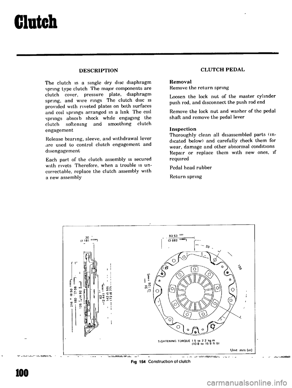
FIg
154
Construction
of
clutch
100
CLUTCH
PEDAL
Removal
Remove
the
return
sprmg
Loosen
the
lock
nut
of
the
master
cyhnder
push
rod
and
disconnect
the
push
rod
end
Remove
the
lock
nut
and
washer
of
the
pedal
shaft
and
remove
the
pedal
lever
Inspection
Thoroughly
clean
all
disassembled
parts
m
dlcated
below
and
carefully
check
them
for
wear
damage
and
other
abnormal
conditions
RepaIr
or
replace
them
With
new
ones
If
reqUIred
Pedal
head
rubber
Return
sprIng
9353
3682
00004
lIGHTENING
TORQUE
1
5
to
2
2
kg
m
108
to
159ft
lbl
UOIt
mm
Inl
Page 99 of 136
Transmission
AUTOMATIC
TRANSMISSION
The
model
3N71B
automatic
transmiSSIOn
IS
a
fully
automatic
Unit
consisting
pnmanly
of
3
element
hydrauhc
torque
converter
and
two
planetary
gear
sets
Two
multiple
disc
clut
ches
a
multiple
disc
brake
a
band
brake
and
a
one
way
sprag
clutch
provide
the
fnctlon
elements
reqUired
to
obtain
the
deSired
fun
tlon
of
the
two
planetary
gear
sets
The
two
planetary
gear
sets
give
three
for
ward
ratIOs
and
one
reverse
Changing
of
the
gear
ratIOs
IS
fully
automatic
In
relation
to
vehicle
speed
and
engine
torque
Input
Vehicle
speed
and
engine
mamfold
vacuum
Signals
are
constantly
fed
to
the
transmiSSIOn
to
prOVide
the
proper
gear
ratIO
for
maximum
effiCiency
and
performance
at
all
throttle
openmgs
The
Model
3N71B
has
SIX
selector
poSitIOns
P
R
N
D
2
1
p
Park
pOSitIOn
posItively
locks
the
out
put
shaft
to
the
transmiSSIOn
case
by
means
of
a
lockmg
pawl
to
prevent
the
vehicle
from
rollmg
either
directIOn
ThiS
pOSitIOn
should
be
selected
whenever
the
dnver
leaves
the
vehicle
The
engme
may
be
started
m
Park
pOSition
R
Reverse
range
enables
the
vehicle
to
be
operated
m
a
reverse
direction
N
Neutral
pOSitIOn
enables
the
engine
to
be
started
and
run
Without
dnvIngthe
vehicle
0
Drive
range
IS
used
for
all
normal
driVing
conditions
Dnve
range
has
three
gear
ratios
from
the
startmg
ratIO
to
direct
dnve
2
2
range
prOVides
performance
for
dnvIng
onshppery
surfaces
2
range
can
also
be
used
for
engine
brakmg
2
range
can
be
selected
at
any
vehicle
speed
and
prevents
the
transmlsslOn
from
shifting
out
of
second
gear
108
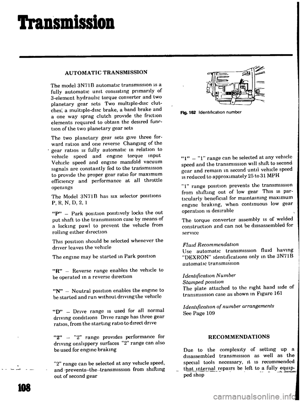
Rg
162
Idenllflcatlon
number
I
1
range
can
be
selected
at
any
vehicle
speed
and
the
transmiSSIOn
will
shift
to
second
gear
and
remain
m
second
until
vehicle
speed
IS
reduced
to
approximately
25
to
31
MPH
1
range
posItion
prevents
the
transmiSSIOn
from
shlftmg
out
of
low
gear
ThiS
IS
par
tlcularly
benefiCial
for
mamtamIng
maximum
engine
brakmg
when
continUOUS
low
gear
operation
IS
deSirable
The
torque
converter
assembly
IS
of
welded
constructIOn
and
can
not
be
dlssassembled
for
service
FlUld
Recommendatwn
Use
automatic
transmiSSIOn
flUid
haVing
DEXRON
IdentificatIOns
only
m
the
3N71B
automatic
transmiSSIOn
denttficatwn
Number
Stamped
posttwn
The
plate
attached
to
the
rIght
hand
Side
of
transmission
case
as
shown
m
Figure
161
denttficatwn
of
number
arrangements
See
Page
109
RECOMMENDATIONS
Due
to
the
compleXity
of
setting
up
a
disassembled
transmissIOn
as
well
as
the
special
tools
necessary
It
IS
recommended
thaL
nternal
epalrs
be
left
to
a
fully
eqUip
ped
shop