1968 DATSUN 510 clutch
[x] Cancel search: clutchPage 91 of 252
10
f
e
2
Weter
pump
gasket
3
Water
pump
tlXlng
bolt
4
Lock
washer
5
Water
pump
tlXlng
bolt
6
Hex
bolt
7
Hex
bolt
8
Lock
washer
9
Fan
pulley
10
Fan
clutch
assembly
11
Cooling
tan
12
Fan
lock
washer
13
Hex
bolt
14
Fan
belt
15
Dealing
assembly
16
Seal
assembly
17
Seatassembly
18
Lock
wire
19
Vane
assembly
20
Hub
pulley
24
Water
pump
seal
kit
Illl
t
l
Page 94 of 252
COOLING
SYSTEM
89
FAN
CLUTCH
Fan
Clutch
Operation
and
Inspection
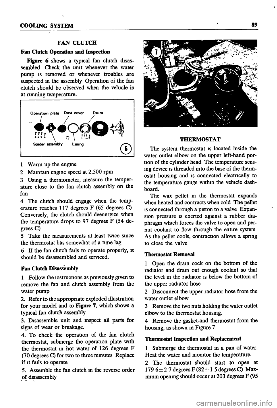
Figure
6
shows
a
typICal
fan
clutch
dISas
sembled
Check
the
umt
whenever
the
water
pump
IS
removed
or
whenever
troubles
are
suspected
m
the
assembly
OperatIon
of
the
fan
clutch
should
be
observed
when
the
vehIcle
is
at
nmning
temperature
Operation
plate
Dust
cover
Drum
o9
Q
SpIder
assembly
LIning
CD
1
Warm
up
the
engme
2
MaIntam
engIne
speed
at
2
500
rpm
3
Usmg
a
thermometer
measure
the
temper
ature
close
to
the
fan
clutch
assembly
on
the
fan
4
The
clutch
should
engage
when
the
temp
erature
reaches
17
degrees
F
65
degrees
C
Conversely
the
clutch
should
deenergIze
when
the
temperature
drops
to
97
degrees
F
54
de
grees
C
5
Take
the
measurements
at
least
twice
SInce
the
thermostat
has
somewhat
of
a
tlme
lag
6
If
the
fan
clutch
falls
to
operate
properly
It
should
be
dIsassembled
and
servIced
Fan
Clutch
Disassembly
1
Follow
the
mstructIons
as
prevIOusly
gIven
to
remove
the
fan
and
clutch
assembly
from
the
water
pump
2
Refer
to
the
appropnate
exploded
illustratIon
for
your
model
and
to
Figure
7
which
shows
a
typiCal
fan
clutch
assembly
3
DIsassemble
unit
and
mspect
all
parts
for
signs
of
wear
or
breakage
4
To
check
the
operatIon
of
the
fan
clutch
thermostat
submerge
the
operatIon
plate
With
the
thermostat
In
hot
water
of
126
degrees
F
70
degrees
C
for
two
to
three
mmutes
Replace
if
It
faIls
to
operate
5
Assemble
the
fan
clutch
m
the
reverse
order
o
dIsassembly
THERMOSTAT
The
system
thermostat
IS
located
inside
the
water
outlet
elbow
on
the
upper
left
hand
por
bon
of
the
cylInder
head
The
temperature
sens
Ing
deVice
IS
threaded
Into
the
base
of
the
therm
ostat
housmg
and
IS
connected
electrlcally
to
the
temperature
gauge
WIthIn
the
vehIcle
dash
board
The
wax
pellet
m
the
thermostat
expands
when
heated
and
contracts
when
cold
The
pellet
IS
connected
through
a
pIston
to
a
valve
Expan
sion
pressure
IS
exerted
agalUst
a
rubber
dIa
phragm
which
forces
the
valve
to
open
and
per
rrut
coolant
to
flow
through
the
entIre
system
As
the
pellet
cools
contractIOn
allows
a
spnng
to
close
the
valve
Thermostat
Removal
1
Open
the
draIn
cock
on
the
bottom
of
the
radiator
and
dram
out
enough
coolant
so
that
the
level
In
the
radIator
IS
below
the
bottom
of
the
upper
radIator
hose
2
DIsconnect
the
upper
radIator
hose
from
the
water
outlet
elbow
3
Remove
the
two
nuts
holdIng
the
water
outlet
elbow
to
the
thermostat
housmg
4
Remove
the
gasket
and
thermostat
from
the
housmg
as
shown
m
FIgure
7
Thermostat
Inspection
and
Replacement
Submerge
the
thermostat
In
a
pan
of
water
Heat
the
water
and
momtor
the
temperature
2
The
thermostat
should
start
to
open
at
1796
1
27
degrees
F
82
1
1
5
degrees
C
Max
Imum
opemng
should
occur
at
203
degrees
F
95
Page 97 of 252
91
CHAPTER
NINE
bon
the
serIes
coll
demagnetizes
agatnst
the
shunt
cOIl
The
return
spnng
causes
the
plunger
to
return
to
the
origmal
posItIon
stoppmg
the
starter
The
overrunnmg
clutch
provIdes
for
positIve
meshmg
and
unmeshmg
of
the
pmlOn
gear
and
flywheerrmg
gear
and
perinitStlie
pmlon
to
overrun
the
armature
after
the
engme
has
started
CONSTRUCIlON
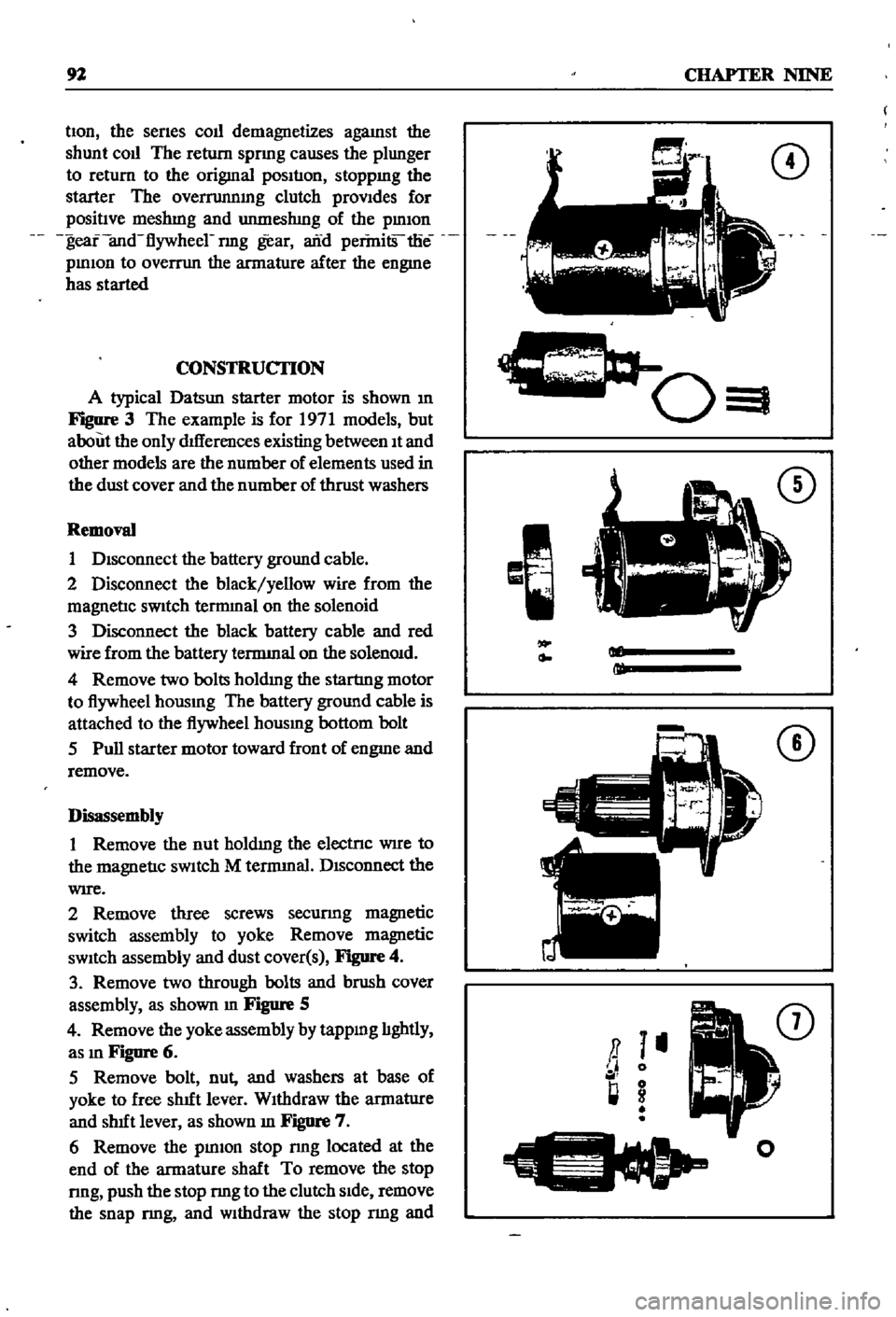
A
typical
Datsun
starter
motor
is
shown
m
Figure
3
The
example
is
for
1971
models
but
about
the
only
dIfferences
existing
between
It
and
other
models
are
the
number
of
elements
used
in
the
dust
cover
and
the
number
of
thrust
washers
Removal
1
DIsconnect
the
battery
ground
cable
2
Disconnect
the
black
yellow
wire
from
the
magnetIc
sWitch
tennmal
on
the
solenoid
3
Disconnect
the
black
battery
cable
and
red
wire
from
the
battery
tennmal
on
the
solenOId
4
Remove
two
bolts
holdmg
the
startmg
motor
to
flywheel
hOUSIng
The
battery
ground
cable
is
attached
to
the
flywheel
hOUSIng
bottom
bolt
5
Pull
starter
motor
toward
front
of
engme
and
remove
Disassembly
1
Remove
the
nut
holdIng
the
electrIc
WIre
to
the
magnetIc
sWItch
M
tennmal
DIsconnect
the
WIre
2
Remove
three
screws
securmg
magnetic
switch
assembly
to
yoke
Remove
magnetic
sWItch
assembly
and
dust
cover
s
Figure
4
3
Remove
two
through
bolts
and
brush
cover
assembly
as
shown
m
Figure
5
4
Remove
the
yoke
assembly
by
tappmg
lIghtly
as
In
Figure
6
5
Remove
bolt
nut
and
washers
at
base
of
yoke
to
free
shut
lever
WIthdraw
the
armatlIre
and
shut
lever
as
shown
m
Figure
7
6
Remove
the
pInIOn
stop
nng
located
at
the
end
of
the
armature
shaft
To
remove
the
stop
nng
push
the
stop
nng
to
the
clutch
SIde
remove
the
snap
nng
and
Withdraw
the
stop
nng
and
CD
c
0
I
CD
Ml
ml
CD
a
I
II
0
l
g
I
o
Page 99 of 252
94
CHAPTER
NINE
clutch
WIthdraw
the
overrunnmg
clutch
assem
bly
from
the
armature
shaft
as
shown
m
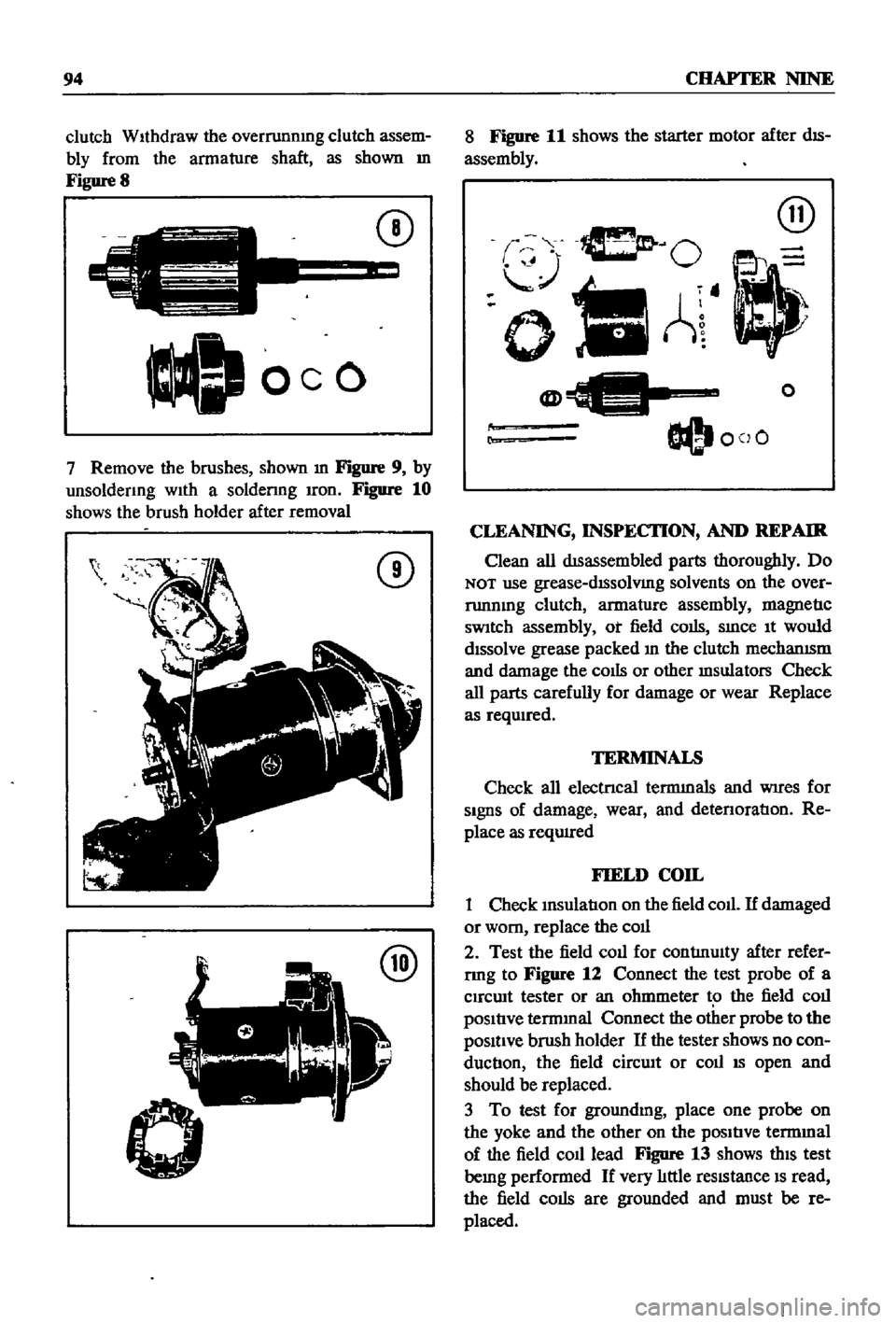
Figure
8
C
J
oeo
CD
7
Remove
the
brushes
shown
m
Figure
9
by
unsoldenng
wIth
a
soldenng
Iron
Figure
10
shows
the
brush
holder
after
removal
CD
@
8
Figure
11
shows
the
starter
motor
after
dIS
assembly
@
O
oIlA
@
O@I
coO
o
r
CLEANING
INSPECI10N
AND
REPAIR
Clean
all
dISassembled
parts
thoroughly
Do
NOT
use
grease
dISsolVIng
solvents
on
the
over
runnmg
clutch
armature
assembly
magnetIc
sWItch
assembly
ot
field
colis
SInce
It
would
dIssolve
grease
packed
In
the
clutch
mechanISm
and
damage
the
cOIls
or
other
msulators
Check
all
parts
carefully
for
damage
or
wear
Replace
as
reqwred
TERMINALS
Check
all
electrIcal
termInals
and
WIres
for
SIgnS
of
damage
wear
and
detenoratIon
Re
place
as
reqUIred
FIELD
COIL
1
Check
InsulatIon
on
the
field
coll
If
damaged
or
worn
replace
the
coll
2
Test
the
field
coll
for
contlnulty
after
refer
rmg
to
Figure
12
Connect
the
test
probe
of
a
Clrcwt
tester
or
an
ohmmeter
t
the
field
coll
pOSItIve
termInal
Connect
the
other
probe
to
the
pOSItIve
brush
holder
If
the
tester
shows
no
con
ductIon
the
field
cirCUIt
or
coll
IS
open
and
should
be
replaced
3
To
test
for
groundmg
place
one
probe
on
the
yoke
and
the
other
on
the
pOSItIve
termmal
of
the
field
co1l1ead
Figure
13
shows
thIS
test
bemg
performed
If
very
lIttle
reSIstance
IS
read
the
field
colis
are
grounded
and
must
be
re
placed
Page 101 of 252
96
CHAFTER
NINE
@
EK
lle
Correct
Incorrect
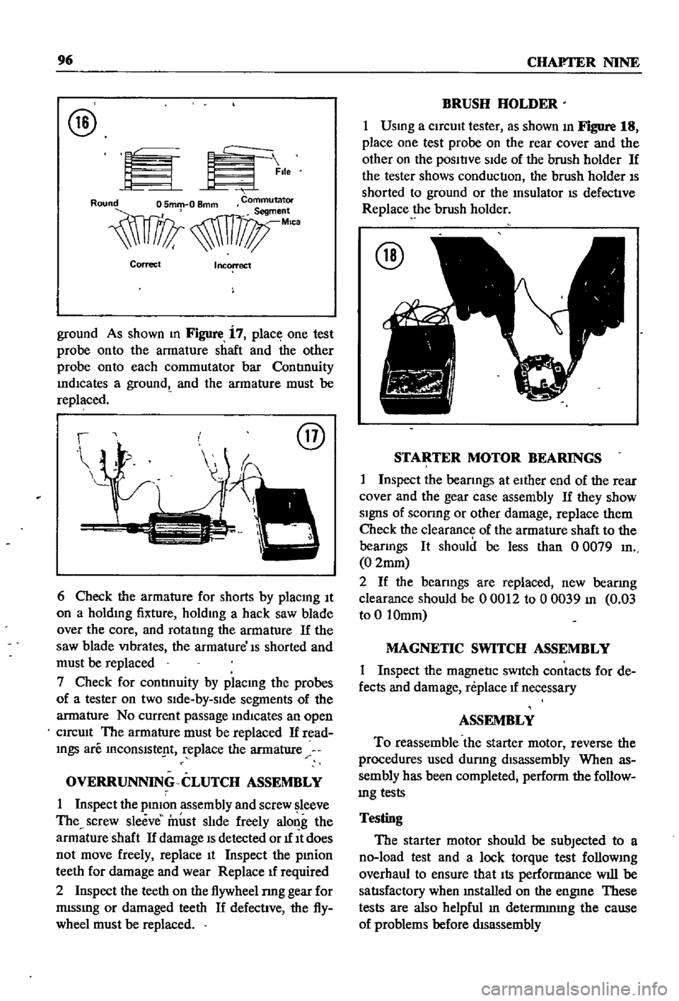
ground
As
shown
m
Figure
i
7
place
one
test
probe
onto
the
armature
shaft
and
the
other
probe
onto
each
commutator
bar
ContInuity
IndICates
a
groundt
and
the
armature
must
be
replaced
@
6
Check
the
armature
for
shorts
by
placmg
It
on
a
holdmg
fixture
holdmg
a
hack
saw
blade
over
the
core
and
rotatIng
the
armature
If
the
saw
blade
VIbrates
the
armature
Is
shorted
and
must
be
replaced
7
Check
for
contInuity
by
placmg
the
probes
of
a
tester
on
two
sIde
by
slde
segments
of
the
armature
No
current
passage
mdlcates
an
open
CIrcUIt
The
armature
must
be
replaced
If
read
mgs
are
InCOnslste
t
replace
the
armature
OVERRUNNING
CLUTCH
ASSEMBLY
1
Inspect
the
plmon
assembly
and
screw
leeve
The
screw
sleeve
must
slIde
freely
along
the
armature
shaft
If
damage
IS
detected
or
1f
It
does
not
move
freely
replace
It
Inspect
the
pmion
teeth
for
damage
and
wear
Replace
1f
required
2
Inspect
the
teeth
on
the
flywheel
nng
gear
for
mlssmg
or
damaged
teeth
If
defective
the
fly
wheel
must
be
replaced
BRUSH
HOLDER
1
Usmg
a
CirCUIt
tester
as
shown
In
Figure
18
place
one
test
probe
on
the
rear
cover
and
the
other
on
the
posltlve
SIde
of
the
brush
holder
If
the
tester
shows
conduction
the
brush
holder
IS
shorted
to
ground
or
the
msulator
IS
defective
Replace
the
brush
holder
@
STARTER
MOTOR
BEARINGS
1
Inspect
the
bearmgs
at
eIther
end
of
the
rear
cover
and
the
gear
case
assembly
If
they
show
SignS
of
sconng
or
other
damage
replace
them
Check
the
clearance
of
the
armature
shaft
to
the
bearmgs
It
should
be
less
than
0
0079
In
0
2mm
2
If
the
bearings
are
replaced
new
bearing
clearance
should
be
00012
to
00039
In
0
03
to
0
10mm
MAGNETIC
SWITCH
ASSEMBLY
1
Inspect
the
magnetic
sWItch
contacts
for
de
fects
and
damage
replace
1f
necessary
ASSEMBLY
To
reassemble
the
starter
motor
reverse
the
procedures
used
dUring
disassembly
When
as
sembly
has
been
completed
perform
the
follow
mg
tests
Testing
The
starter
motor
should
be
subjected
to
a
no
load
test
and
a
lock
torque
test
follOWIng
overhaul
to
ensure
that
Its
performance
will
be
satIsfactory
when
mstalled
on
the
engme
These
tests
are
also
helpful
In
detennmIng
the
cause
of
problems
before
dIsassembly
Page 132 of 252
CHAPTER
ELEVEN
CLUTCH
TRANSMISSION
AND
DRIVESHAFf
CLUTCH
i
es
ription
Datsun
uses
a
single
dry
dtsc
clutch
with
dIaphragm
spring
The
major
components
are
clutch
cover
pressure
plate
dIaphragm
spring
and
WIre
nngs
The
clutch
dISC
has
riveted
plates
on
both
surfaces
and
coll
spnngs
arranged
in
a
link
The
coll
springs
absorb
shock
to
soften
and
smooth
clutch
engagement
Figure
1
next
page
is
an
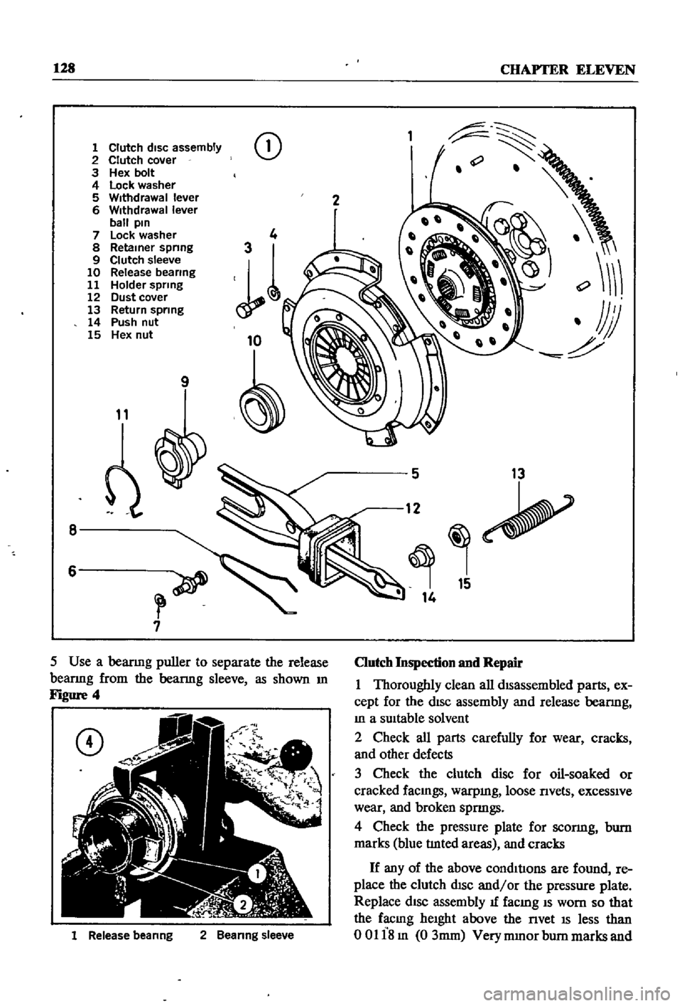
exploded
diagram
of
the
clutch
assembly
Clutch
Removal
The
transmIssion
must
be
separated
from
the
engme
to
remove
tlte
clutch
assembly
This
can
be
done
by
removmg
the
transmISSIon
and
engme
from
the
vehicle
as
a
umt
or
by
remoVIng
the
transmiSSIon
separately
Removal
of
the
engine
and
transmissIOn
IS
descnbed
In
Chapter
Six
Removal
of
the
transmISSIon
only
IS
descnbed
later
in
tills
chapter
Outcb
Disassembly
1
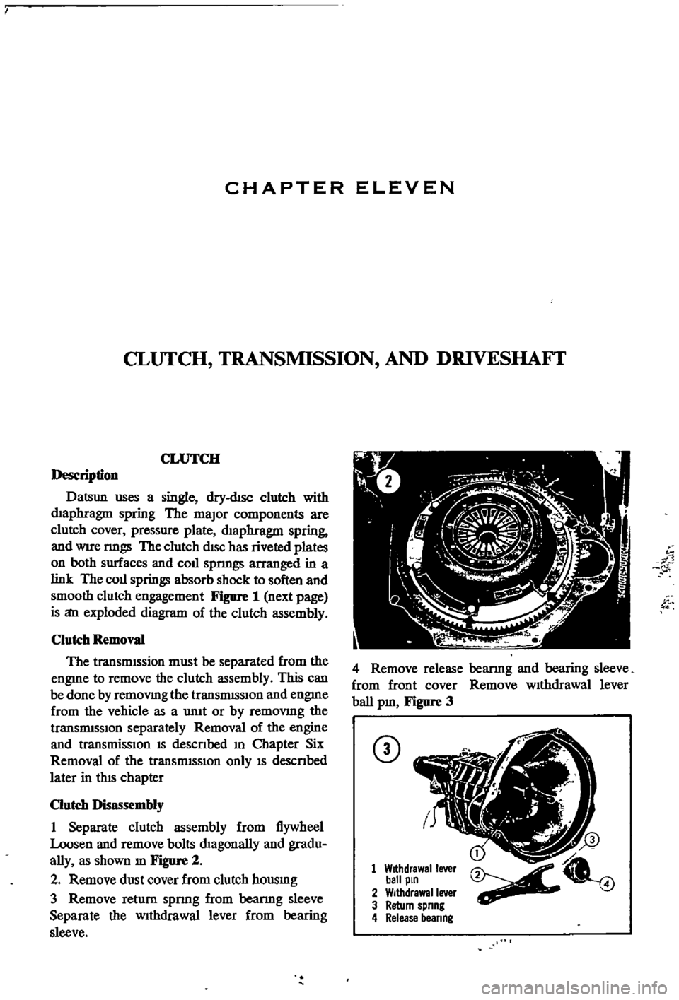
Separate
clutch
assembly
from
flywheel
Loosen
and
remove
bolts
dIagonally
and
gradu
ally
as
shown
m
Figure
2
2
Remove
dust
cover
from
clutch
housmg
3
Remove
return
spnng
from
beanng
sleeve
Separate
the
Withdrawal
lever
from
bearing
sleeve
w
1
4
Remove
release
bearmg
and
bearing
sleeve
from
front
cover
Remove
wIthdrawal
lever
ball
pm
Figure
3
CD
1
Withdrawal
lever
ball
pin
2
Withdrawal
lever
3
Return
spnng
4
Release
beanng
4
Page 133 of 252
128
CHAPTER
ELEVEN
1
Clutch
disc
assembly
2
Clutch
cover
3
Hex
bolt
4
Lock
washer
5
Withdrawal
lever
6
Withdrawal
lever
ball
pin
7
Lock
washer
8
Retainer
spnng
9
Clutch
sleeve
10
Release
bearing
11
Holder
spring
12
Dust
cover
13
Return
spring
14
Push
nut
15
Hex
nut
CD
9
11
8
6
7
1
Release
beanng
2
Beanng
sleeve
2
5
13
12
15
14
Clutch
Inspection
and
Repair
1
Thoroughly
clean
all
dISassembled
parts
ex
cept
for
the
dISc
assembly
and
release
bearmg
In
a
SUItable
solvent
2
Check
all
parts
carefully
for
wear
cracks
and
other
defects
3
Check
the
clutch
disc
for
oil
soaked
or
cracked
faCIngs
warpmg
loose
nvets
exceSSIve
wear
and
broken
spnngs
4
Check
the
pressure
plate
for
sconng
bum
marks
blue
tlnted
areas
and
cracks
If
any
of
the
above
condItIons
are
found
re
place
the
clutch
dISC
and
or
the
pressure
plate
Replace
dISC
assembly
1f
facmg
IS
worn
so
that
the
facmg
heIght
above
the
nvet
IS
less
than
00118m
03mm
Very
mmor
bum
marks
and
Page 134 of 252
CLUTCH
TRANSMISSION
AND
DRIVESHAFI
129
scratches
on
the
pressure
plate
may
be
removed
with
crocus
cloth
If
the
source
of
clutch
trouble
IS
still
not
evl
dent
take
the
pressure
plate
and
disc
to
a
compe
tent
garage
to
check
the
pressure
plate
finger
release
height
and
nmout
Never
attempt
to
ad
just
the
fingers
or
dismantle
the
pressure
plate
Without
proper
tools
and
experience
Check
the
release
bearing
by
holdmg
the
Inner
race
and
rotatmg
the
outer
race
With
hght
pres
sure
applied
If
the
bearing
is
rough
or
noisy
replace
it
CAUTION
Never
clean
the
release
bearing
In
solvent
It
IS
prelubriCflted
at
the
fac
tory
Simply
wipe
with
a
Unt
free
cloth
If
the
release
bearing
shows
any
signs
of
loss
of
lubncant
install
a
new
bearing
Replace
the
sleev
lu
SignS
of
wear
are
evident
Clutch
Reassembly
1
Be
sure
your
hands
are
clean
for
the
initIal
assembly
2
Inspect
the
clutch
facings
pressure
plate
and
flywheel
to
be
sure
they
are
free
from
grease
oil
and
other
foreIgn
material
3
TIghtly
fit
release
bearmg
onto
the
bearing
sleeve
When
beanng
IS
mstalled
turn
bearmg
With
a
finger
to
make
sure
It
operates
smoothly
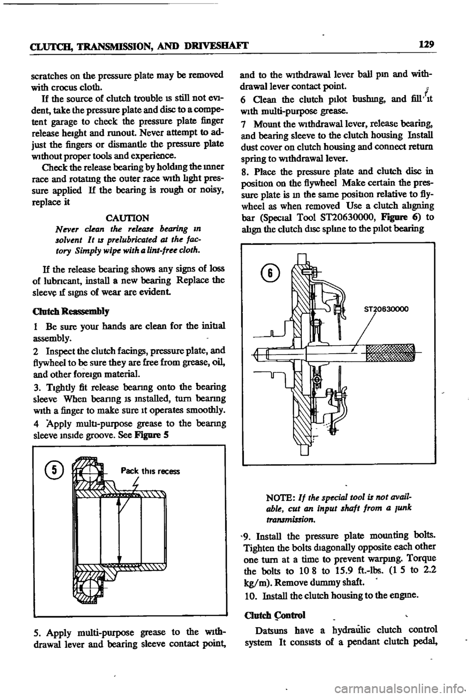
4
Apply
multI
purpose
grease
to
the
bearmg
sleeve
InSIde
groove
See
Figure
5
CD
Ji
rot
Pac
thiS
r
r
r
1
1i
QI
ecess
5
Apply
multi
purpose
grease
to
the
WIth
drawallever
and
bearing
sleeve
contact
point
and
to
the
Withdrawal
lever
ball
pm
and
with
drawallever
contact
point
f
6
Clean
the
clutch
pllot
bushmg
and
fill
It
With
multi
purpose
grease
7
Mount
the
WithdraWal
lever
release
bearing
and
bearing
sleeve
to
the
clutch
housing
Install
dust
cover
on
clutch
housing
and
connect
return
spring
to
WithdraWal
lever
8
Place
the
pressure
plate
and
clutch
disc
in
positIon
on
the
flywheel
Make
certain
the
pres
sure
plate
is
In
the
same
positIon
relative
to
fly
wheel
as
when
removed
Use
a
clutch
alIgning
bar
Special
Tool
ST20630000
FIgDfe
6
to
alIgn
the
clutch
dISc
splIne
to
the
pllot
bearing
CD
NOTE
If
the
special
tool
is
not
avail
able
cut
an
input
shaft
from
a
Junk
transmission
9
Install
the
pressure
plate
mounting
bolts
Tighten
the
bolts
dIagonally
opposite
each
other
one
turn
at
a
time
to
prevent
warpmg
Torque
the
bolts
to
10
8
to
15
9
ft
lbs
1
5
to
2
2
kg
m
Remove
durmny
shaft
10
Install
the
clutch
housing
to
the
engme
Clutch
ntrol
Datsuns
have
a
hydraulic
clutch
control
system
It
consISts
of
a
pendant
clutch
pedal