1968 DATSUN 510 clutch
[x] Cancel search: clutchPage 146 of 252
CLUTCH
TRANSMISSION
AND
DRlVESHAFI
141
22
Remove
the
thrust
washer
and
mam
shaft
1st
speed
gear
complete
With
needle
roller
bear
mg
Be
careful
not
to
lose
the
small
steel
ball
which
locates
the
thrust
washer
Remove
main
shaft
1st
gear
bushmg
23
Remove
the
mam
shaft
2nd
speed
gear
and
needle
roller
bearmg
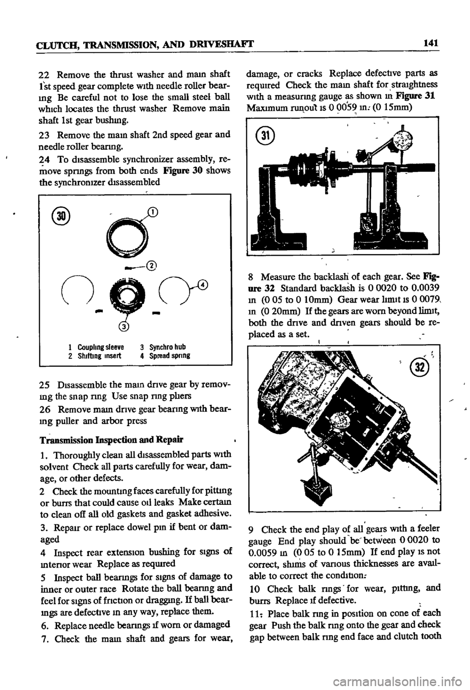
24
To
dISassemble
synchronizer
assembly
re
move
sprmgs
from
both
ends
Figure
30
shows
the
synchronIZer
dIsassembled
@
d
@
n
9
cr
1
Coupling
slee
e
3
Synchro
hub
2
Shlftmg
msert
4
Spread
spnng
25
DIsassemble
the
mam
dnve
gear
by
remov
mg
the
snap
nng
Use
snap
nng
phers
26
Remove
mam
dnve
gear
bearmg
With
bear
Ing
puller
and
arbor
press
Transmission
Inspection
and
Repair
1
Thoroughly
clean
all
dtsassembled
parts
With
solvent
Check
all
parts
carefully
for
wear
dam
age
or
other
defects
2
Check
the
mountIng
faces
carefully
for
pittIng
or
burrs
that
could
cause
011
leaks
Make
certatn
to
clean
off
all
old
gaskets
and
gasket
adhesive
3
RepaIr
or
replace
dowel
pm
if
bent
or
dam
aged
4
Inspect
rear
extensIon
bushing
for
SIgnS
of
mtenor
wear
Replace
as
reqUIred
5
Inspect
ball
bearmgs
for
SIgnS
of
damage
to
inner
or
outer
race
Rotate
the
ball
bearmg
and
feel
for
SIgnS
of
fnctIon
or
draggmg
If
ball
bear
mgs
are
defectIve
In
any
way
replace
them
6
Replace
needle
bearIngs
1f
wom
or
damaged
7
Check
the
mam
shaft
and
gears
for
wear
damage
or
cracks
Replace
defectIve
parts
as
required
Check
the
maIn
shaft
for
straIghtness
WIth
a
measurmg
gauge
as
shown
m
Figure
31
MaxImum
runpulls
0
0059
m
0
15mm
@
8
Measure
the
backlasH
of
each
gear
See
Fig
nre
32
Standard
backlash
is
0
0020
to
0
0039
In
0
05
to
0
10mm
Gear
wear
hrmt
IS
0
0079
In
0
20mm
If
the
gears
are
worn
beyond
limtt
both
the
dnve
and
dnven
gears
should
be
re
placed
as
a
set
@
9
Check
the
end
play
of
all
gears
WIth
a
feeler
gauge
End
play
should
be
between
0
0020
to
0
0059
m
005
to
0
15mm
If
end
play
IS
not
correct
Sh1nIS
of
vanous
thicknesses
are
avail
able
to
correct
the
condItIon
10
Check
balk
nngs
for
wear
plttmg
and
burrs
Replace
1f
defective
11
Place
balk
rmg
in
pOSItion
on
cone
of
each
gear
Push
the
balk
rmg
onto
the
gear
and
check
gap
between
balk
nng
end
face
and
clutch
tooth
Page 148 of 252
CLUTCH
TRANSMISSION
AND
DRlVESHAFI
143
dnve
gear
counter
gear
and
reverse
Idler
gear
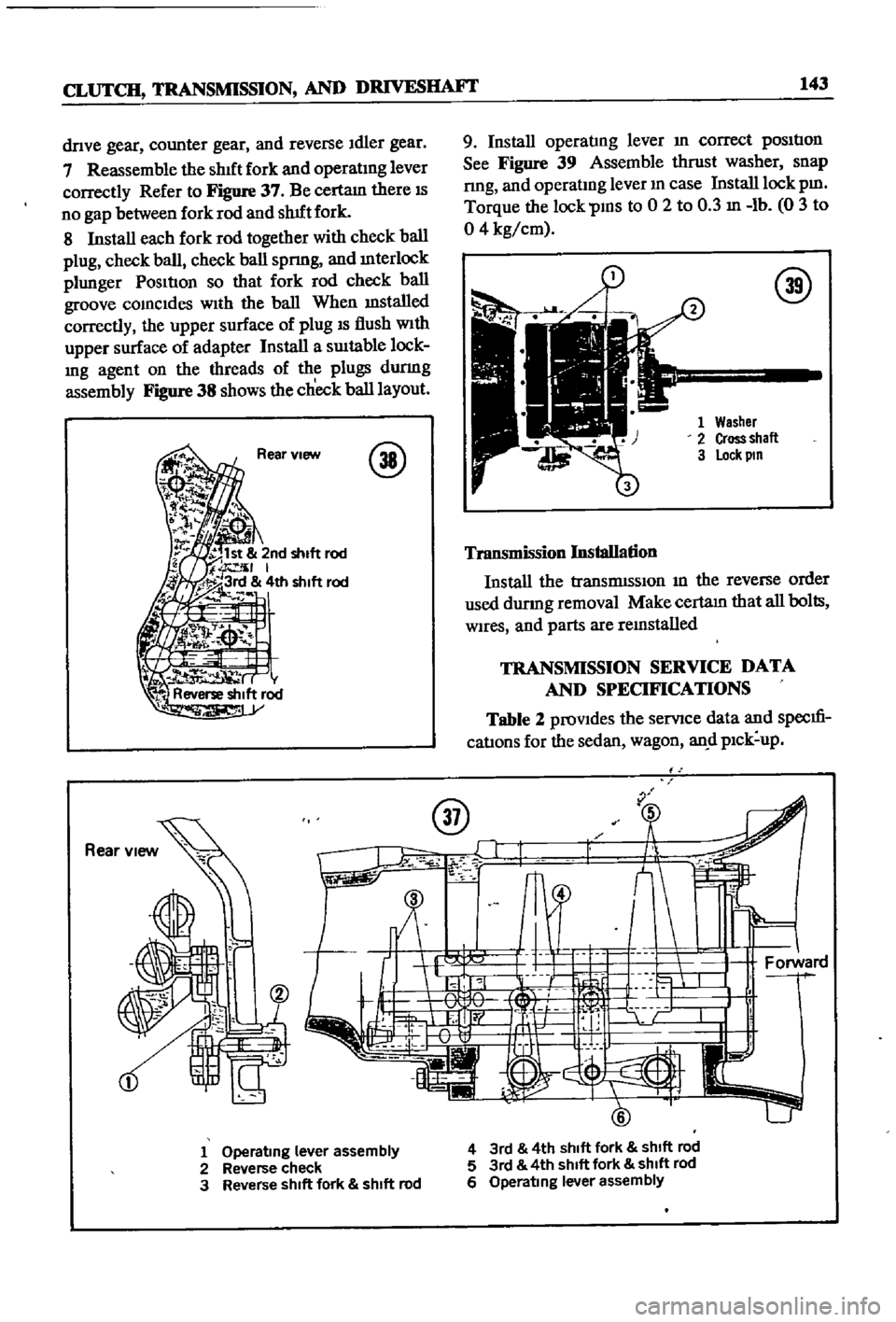
7
Reassemble
the
shIft
fork
and
operatIng
lever
correctly
Refer
to
Figure
37
Be
certam
there
IS
no
gap
between
fork
rod
and
shUt
fork
8
Install
each
fork
rod
together
with
check
ball
plug
check
ball
check
ball
spnng
and
mterlock
plunger
PosItIon
so
that
fork
rod
check
ball
groove
comcldes
wIth
the
ball
When
mstalled
correctly
the
upper
surface
of
plug
IS
flush
With
upper
surface
of
adapter
Install
a
sUItable
lock
Ing
agent
on
the
threads
of
the
plugs
durmg
assembly
Figure
38
shows
the
check
ball
layout
@
9
Install
operatIng
lever
In
correct
pOSItIon
See
Figure
39
Assemble
thrust
washer
snap
nng
and
operatlDg
lever
m
case
Install
lock
pm
Torque
the
lock
PIDS
to
0
2
to
0
3
In
lb
0
3
to
04
kg
cm
@
Washer
Cross
shall
lock
pm
Transmission
Installation
Install
the
tranSmISSIon
m
the
reverse
order
used
durmg
removal
Make
certam
that
all
bolts
Wires
and
parts
are
remstalled
TRANSMISSION
SERVICE
DATA
AND
SPECIFICATIONS
Table
2
proVIdes
the
servlce
data
and
specm
catIons
for
the
sedan
wagon
an
d
pIck
up
u
1
Operating
lever
assembly
2
Reverse
check
3
Reverse
shift
fork
shift
rod
4
3rd
4th
shift
fork
shift
rod
5
3rd
4th
shIft
fork
shift
rod
6
Operating
lever
assembly
Page 150 of 252
CLUTCH
TRANSMISSION
AND
DRIVESIIAFT
145
r
@
l
S
St
P
t
ii
t
1
1
1
0
8
12
3
5
8
12
13
i
f
p
1
2
5
7
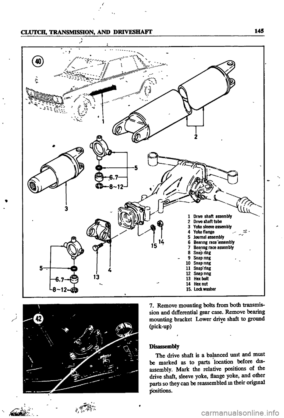
Remove
mounting
bolts
from
both
transmis
sion
and
dllIerential
gear
case
Remove
bearing
mounting
bracket
Lower
drive
shaft
to
ground
pick
up
J
iw
sembly
The
drive
shaft
is
a
balanced
unIt
and
must
be
marked
as
to
parts
location
before
dIS
assembly
Mark
the
relative
positions
of
the
drive
shaft
sleeve
yoke
flange
yoke
and
other
parts
so
they
can
be
reassembled
m
their
origmal
positions
Page 152 of 252
CLUTCH
TRANSMISSION
AND
DRIVESHAFI
147
SERVICE
DATA
AND
SPECIFICATIONS
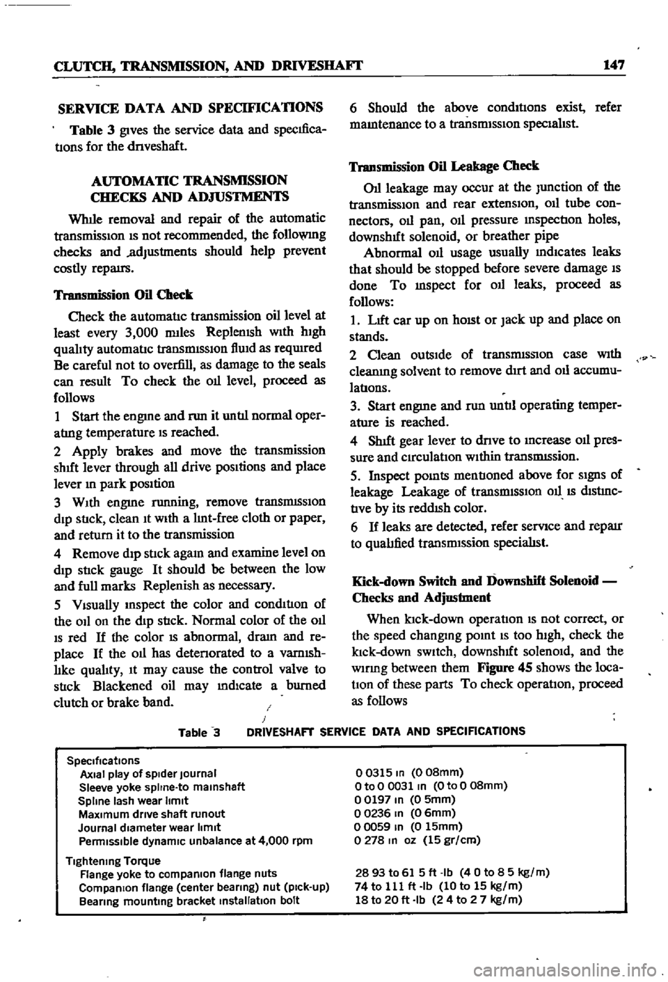
Table
3
gives
the
service
data
and
specIfica
tIons
for
the
dnveshaft
AUTOMATIC
TRANSMISSION
CHECKS
AND
ADJUSTMENTS
Whlle
removal
and
repair
of
the
automatic
transmisSIOn
IS
not
recommended
the
follo
VlIlg
checks
and
adjustments
should
help
prevent
costly
repatrs
Transmission
Oil
Check
Check
the
automatIc
transmission
oil
level
at
least
every
3
000
mlles
Replemsh
With
hIgh
qualIty
automatIc
transmISSIon
flUId
as
reqUIred
Be
careful
not
to
overfill
as
damage
to
the
seals
can
result
To
check
the
011
level
proceed
as
follows
1
Start
the
engme
and
nm
it
untIl
normal
oper
atrng
temperature
IS
reached
2
Apply
brakes
and
move
the
transmission
shut
lever
through
all
drive
pOSItions
and
place
lever
In
park
position
3
WIth
engme
running
remove
tranSmISSIon
dIp
StIck
clean
It
WIth
a
lInt
free
cloth
or
paper
and
return
it
to
the
transmission
4
Remove
dIp
stIck
agam
and
examine
level
on
dIp
stIck
gauge
It
should
be
between
the
low
and
full
marks
Replenish
as
necessary
5
VIsually
InSpect
the
color
and
condItIon
of
the
OIl
on
the
dIp
stIck
Normal
color
of
the
OIl
IS
red
If
the
color
IS
abnormal
dram
and
re
place
If
the
011
has
detenorated
to
a
vamlsh
lIke
qualIty
It
may
cause
the
control
valve
to
stIck
Blackened
oil
may
mdlcate
a
burned
clutch
or
brake
band
6
Should
the
above
condItIons
exist
refer
mamtenance
to
a
transmISSIon
specIalIst
Transmission
Oil
Leakage
Check
011
leakage
may
occur
at
the
Junction
of
the
transmissIon
and
rear
extensIon
011
tube
con
nectors
011
pan
OIl
pressure
mspectIon
holes
downshIft
solenoid
or
breather
pipe
Abnormal
OIl
usage
usually
mdlcates
leaks
that
should
be
stopped
before
severe
damage
IS
done
To
mspect
for
011
leaks
proceed
as
follows
1
LIft
car
up
on
hOISt
or
Jack
up
and
place
on
stands
2
Clean
outsIde
of
transmISSIon
case
With
cleanIng
solvent
to
remove
dIrt
and
011
accumu
latIons
3
Start
engme
and
nm
untIl
operating
temper
ature
is
reached
4
ShIft
gear
lever
to
dnve
to
Increase
011
pres
sure
and
CIrculatIon
WIthin
tranSmISsion
5
Inspect
pOInts
mentIoned
above
for
SIgnS
of
leakage
Leakage
of
transrmSSIOn
011
IS
dIStrnC
tIve
by
its
reddISh
color
6
If
leaks
are
detected
refer
servIce
and
reparr
to
qualIfied
transrmssion
specialISt
Kick
down
Switch
and
Downshift
Solenoid
Checks
and
Adjustment
When
ktck
down
operatIon
IS
not
correct
or
the
speed
changmg
pomt
IS
too
high
check
the
klck
down
SWItch
downshIft
solenOId
and
the
wlDng
between
them
Figure
45
shows
the
loca
tIOn
of
these
parts
To
check
operatIon
proceed
as
follows
Table
3
J
DRIVESHAFT
SERVICE
DATA
AND
SPECIFICATIONS
SpeCifications
Axial
play
of
spider
Journal
Sleeve
yoke
spltne
to
malnshaft
Spline
lash
wear
Itmlt
MaXimum
drive
shaft
runout
Journal
diameter
wear
limit
Penmlsslble
dynamiC
unbalance
at
4
000
rpm
Tightening
Torque
Flange
yoke
to
compaRlon
flange
nuts
CompaRlon
flange
center
bearing
nut
pick
up
Bearing
mounting
bracket
installation
bolt
00315
In
008mm
OtoO
0031
In
OtoO
08mm
00197
In
0
5mm
00236
In
06mm
00059
In
0
15mm
0278
In
oz
15
gr
cm
2893
to
615ft
Ib
40
to
8
5
kg
m
74
to
111
ft
Ib
10
to
15
kg
m
18
to
20
ft
Ib
24
to
2
7
kg
m
Page 215 of 252
110
CHAPTER
FIFTEEN
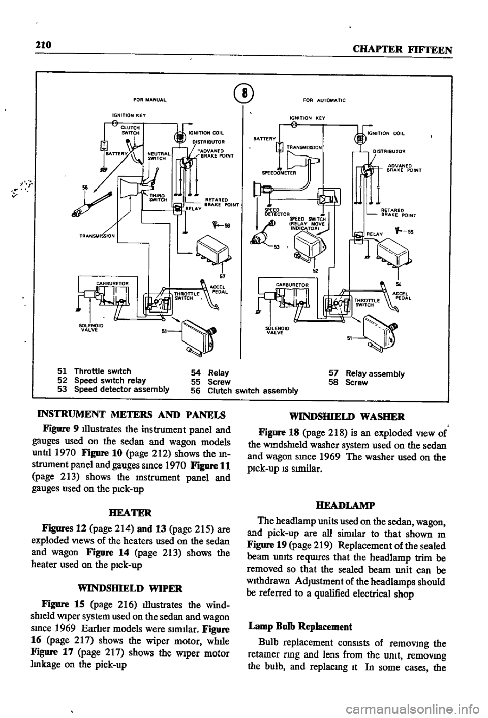
FOR
MANUAL
IGNITION
KEY
i
I
MADV
Nf
D
BRAKE
POINT
v
sa
tS
57
51
Th
rottle
sWItch
52
Speed
sWItch
relay
53
Speed
detector
assembly
Q
FOR
AUTOMATIC
IGNITION
KEY
AOVANEO
BRAKE
POINT
I
SPEED
DETECTOR
SPEED
SWITCH
I
RELAY
MJsr
I
IQ
52
SOLENOID
VALVE
54
Relay
55
Screw
56
Clutch
sWItch
assembly
57
Relay
assembly
58
Screw
INSTRUMENT
METERS
AND
PANELS
Figure
9
Illustrates
the
instrument
panel
and
gauges
used
on
the
sedan
and
wagon
models
untIl
1970
Figure
10
page
212
shows
the
m
strument
panel
and
gauges
smce
1970
Figure
11
page
213
shows
the
lDstrument
panel
and
gauges
used
on
the
pick
up
HEATER
Figures
12
page
214
and
13
page
215
are
exploded
Views
of
the
heaters
used
on
the
sedan
and
wagon
FigDre
14
page
213
shows
the
heater
used
on
the
pick
up
WINDSHIELD
WIPER
Figure
15
page
216
illustrates
the
wind
shield
Wiper
system
used
on
the
sedan
and
wagon
smce
1969
Earlier
models
were
slrmlar
Figure
16
page
217
shows
the
wiper
motor
wlule
Figure
17
page
2
I
7
shows
the
Wiper
motor
Imkage
on
the
pick
up
WINDSHIELD
WASHER
Figure
18
page
218
is
an
exploded
View
of
the
WindshIeld
washer
system
used
on
the
sedan
and
wagon
smce
1969
The
washer
used
on
the
pick
up
IS
SImilar
HEADLAMP
The
headlamp
units
used
on
the
sedan
wagon
and
pick
up
are
all
similar
to
that
shown
m
Figure
19
page
219
Replacement
of
the
sealed
beam
UnIts
reqwres
that
the
headlamp
trim
be
removed
so
that
the
sealed
beam
unit
can
be
withdrawn
AdJustment
of
the
headlamps
should
be
referred
to
a
qualified
electrical
shop
Lamp
Bulb
Replacement
Bulb
replacement
consIsts
of
removmg
the
retamer
nng
and
lens
from
the
unit
removmg
the
bulb
and
replacmg
It
In
some
cases
the
Page 242 of 252
236
INDEX
Clutch
DescnptIon
DIsassembly
Bleedmg
Exploded
vIew
Hydraulic
clutch
control
InspectIOn
and
repair
InstallatIOn
Reassembly
Removal
SpecificatIons
and
service
data
TroubleshootIng
Withdrawal
lever
Clutch
master
cylinder
Exploded
views
InspectIon
and
reassembly
InstallatIOn
Removal
and
disassembly
putch
operatmg
cylinder
J
Inspection
I
jj
ReaSs
mbly
and
mslallatlOn
Removal
and
disassembly
Clutch
wllhdrawal
lever
Condenser
Connectmg
rods
Beanng
mspectIon
Connectmg
rod
bearmg
underslzes
DescrIptIOn
InspestIon
Reassembly
Cooling
system
D
scrIpt
Qn
Fan
clutch
Radlato
Thermostat
yvater
pump
Crankshaft
DescrIptIon
Exploded
View
Inspection
Mam
bearIng
underslzes
iPulley
mstallahon
r
Reassembly
Removal
Sprocket
Tlmmg
cham
Cylinder
block
Bore
measurement
Camshaft
bend
DesCrIpllOn
Exploded
view
InspectIOn
eassembly
Cylinder
head
DescrIptIon
f
DIsassembly
r
Exploded
View
InspectIOn
InstallatIOn
l
or
1
Reassembly
127
Removal
127
133
128
D
129
DifferentIal
pick
up
128
59
InstallatIon
129
Removal
and
mspecllOn
127
SectIOnal
view
134
Differential
sedan
15
Exploded
view
133
Inspection
InstallatIOn
131
132
LubrIcant
level
130
Removal
130
DifferentIal
wagon
130
Exploded
view
InstallatIon
132
Removal
and
mspecllon
133
DistrIbutor
132
Cap
and
rotor
head
133
Condenser
110
ConstructIon
DIsassembly
and
reassembly
52
Dwell
angle
52
Exploded
Views
34
IgmtIon
coIl
51
Inspection
and
service
54
Pomts
Removal
84
SpeCificatIons
89
Tlmmg
dual
pomt
distrIbutor
90
Door
lock
and
regulator
89
Exploded
view
pick
up
85
Exploded
View
sedan
and
wagon
Doors
31
Construction
35
Exploded
view
4
door
sedan
51
Exploded
vIew
pick
up
52
DrIveshaft
58
DescrIptIOn
57
Disassembly
43
Exploded
Views
53
InspectIon
and
repaIr
57
Reassembly
Removal
49
SpeCificatIons
and
service
data
48
31
E
33
49
ElectrIcal
system
body
55
Fuses
Headlamps
34
Heater
45
Instrument
meters
and
panels
36
SWitches
and
fuses
46
Wmdshleld
wipers
56
Wmng
53
43
162
162
163
150
151
151
149
149
157
157
157
106
110
105
110
24
106
109
111
21
110
40
112
24
228
229
225
227
228
144
145
145
146
146
146
144
147
217
210
210
210
205
207
210
210
205
Page 243 of 252
INDEX
237
2
7
30
28
WIrIng
diagrams
WIrIng
harnesses
Electncal
system
engme
Alternator
Chargmg
ClfCUlt
Dlstnbutor
IgmtlOn
coIl
Spark
plugs
Starter
Voltage
regulator
Emission
control
crankcase
DescnptIon
General
mspectIon
SchematIc
vIew
VentIlatIOn
control
valve
EmIssIOn
control
exhaust
AIr
pump
AntI
backfire
valve
Check
valve
DescnptlOn
Engme
modificatIons
system
Exploded
and
schematIc
vIews
Mamtenance
and
testIng
Troubleshootmg
Emission
control
system
evaporatIve
Engme
Camshaft
and
beanngs
Camshaft
sprocket
Component
descnptIons
Componenl
reassembly
and
mstallatIon
CompressIOn
testmg
Connectmg
rod
beanngs
Connectmg
rods
Crankshaft
Crankshaft
and
tImmg
cham
Crankshafl
sprocket
Cylmder
block
CylInder
head
DescnptlOn
Disassembly
Exploded
view
Flywheel
InstallatIOn
LubncatIon
MaIO
bearmgs
PIston
nngs
Pistons
and
connectmg
rods
PiStOns
and
piston
pms
Reassembly
Removal
SectIonal
views
ServIce
data
SpeCificatIons
Troubleshootmg
Valve
rocker
PIvot
Valves
Engme
lubncatlon
DescnptIon
217
222
205
207
98
104
98
105
111
111
112
113
9197
104
122
122
121
38
114
123
115
120
114
15
123
48
54
53
31
38
5759
24
52
51
54
51
57
53
49
55
46
56
31
40
33
53
59
27
30
52
50
45
50
54
53
38
32
60
61
60
61
13
54
47
53
114
114
121
114
LubncatlOn
ClfCUlt
011
filter
011
pump
Engme
tune
up
Checks
miscellaneous
Compression
testIng
DIstributor
Dwell
angle
EqUIpment
usage
ReqUIred
eqUIpment
Spark
plugs
Tlmmg
Tlmmg
dual
pomt
dlstnbutor
Valve
clearances
Exhaust
systems
Exploded
views
InspectIon
InstallatIOn
Removal
pickup
Removal
sedan
and
wagon
F
Fan
clutch
DIsassembly
and
reassembly
OperatIon
and
mspectlon
Flywheel
Fuel
pump
Capacity
test
DescnptlOn
Exploded
views
InspectIOn
InstallatIOn
Reassembly
Removal
an
assembly
StatIc
pressure
test
Fuel
stramer
Fuel
system
Air
cleaner
Carburetor
Fuel
pump
Fuel
stramer
Fuel
tank
Troubleshootmg
Fuel
tank
DescnptIon
Exploded
Views
InspectIOn
and
repaIr
Installation
Removal
sedan
Removal
pick
up
Removal
wagon
Fuses
G
27
General
mformatIon
25
24
21
24
20
20
21
23
24
25
124
126
126
126
126
123
l
89
89
53
68
37
65
66
67
68
58
68
42
68
65
1
2v
62
69
65
68
l
6
7
1
l
76
78
81
82
82
76
82
7
6
2
1
F
Page 245 of 252
l
INDEX
239
Rear
suspensIOn
wagon
Removal
40
92
Servlcmg
161
Termmals
94
Tightening
torques
162
Test
diagnosIs
97
Testmg
96
Troubleshootmg
10
5
Steenng
also
see
Suspension
front
I
Exploded
views
182
185
L
Seats
SpecIfications
186
DescnptIon
228
Troubleshooting
16
Exploded
View
front
4
door
sedan
232
SuspensIOn
front
pick
up
Exploded
VIew
front
pick
up
228
Axle
removal
175
Service
hmts
4
Inspection
and
repair
179
Shock
absorbers
sedan
154
Installation
179
Shock
absorbers
wagon
162
Posture
adjustment
181
Spark
plugs
Removal
177
CondlllOn
chart
21
Wheel
abgnment
182
InspectIon
and
servlcmg
21
Wheel
bearmg
adjustment
177
Recommended
types
112
Suspension
front
sedan
and
wagon
SpecificatIOns
and
tables
Inspection
and
repair
176
Adjustment
and
wheel
alignment
175
InstallatIOn
177
Brake
service
data
203
204
Lower
ball
Jomt
174
Brakes
203
204
Spnng
and
strut
assembly
173
Camshaft
beanngs
48
Stabilizer
173
Caster
and
camber
sedan
and
wagon
175
TenSIOn
rod
173
Clutch
134
Transverse
bnk
174
Clutch
service
data
134
Wheel
beanngs
177
Connectmg
rod
beanng
underslzes
52
Wheel
hubs
and
bearmgs
168
173
Dlstnbutor
112
SWItches
Dnveshaft
147
DescnptIon
205
Dnveshaft
service
dala
147
Exploded
View
through
1969
208
Engme
60
61
Exploded
view
1970
1972
207
Engme
service
data
60
61
General
4
Mam
bearmg
underslzes
52
T
Piston
rmg
gap
50
Rear
suspenSIOn
pick
up
167
Tail
gate
228
233
Rear
suspensIOn
torques
wagon
162
TenSIOn
rod
sedan
and
wagon
173
Steermg
186
Thermostat
TransmiSSion
manual
144
DescnptIon
89
TransmiSSion
service
data
manual
144
Inspection
and
replacement
89
Valve
spnng
47
Removal
89
Sprmg
and
strut
assembly
sedan
and
wagon
173
Tires
Spnngs
sedan
154
Wear
analYSIS
17
Stabilizer
sedan
and
wagon
173
TransmiSSion
automatic
Starter
Downshift
solenOid
147
Armature
95
Inhlbllor
SWItch
148
Beanngs
96
Kick
down
SWitch
147
Brush
holder
96
Lmkage
mspectIon
and
adjustment
148
Brushes
and
lead
WIre
95
011
checks
147
Cleaning
mspectIon
and
repair
94
Oil
leakage
147
Construcllon
92
TransmiSSion
manual
Disassembly
92
DescnptIon
134
Exploded
View
93
Disassembly
138
Field
COIl
94
Exploded
view
138
Magnetic
SWItch
96
Gear
assembly
exploded
view
139
Magnetic
SWItch
assembly
test
97
Inspection
and
repair
141
Operation
91
Installation
143
Overrunnmg
clutch
96
Reassembly
and
adjustment
142
Reassembly
96
Removal
134