1900 MITSUBISHI DIAMANTE engine
[x] Cancel search: enginePage 45 of 408
.
I-46 GENERALINFORMATIONAND MAINTENANCE
2. Pull the jumping vehicle (with the good bat-
tery) into a position so the jumper cables can reach
the dead battery and that vehicle’s engine. Make sure
that the vehicles do NOT touch.
3. Place the transmissions/transaxles of both ve-
hicles in Neutral (MT) or P (AT), as applicable, then
firmly set their parking brakes.
*ff necessary for safety reasons, the hazard
lights on both vehicles may be operated
throughout the entire procedure without sig-
nificantiy increasing the diff icuity of jumping
the dead battery.
4. Turn all lights and accessories OFF on both
vehicles. Make sure the ignition switches on both ve-
hicles are turned to the OFF position.
5. Cover the battery cell caps with a rag, but do
not cover the terminals.
6. Make sure the terminals on both batteries are
clean and free of corrosion or proper electrical con-
nection will be impeded. If necessary, clean the bat-
tery terminals before proceeding.
7. Identify the positive (+) and negative (-) termi-
nals on both batteries.
8. Connect the first jumper cable to the positive
(t) terminal of the dead battery, then connect the
other end of that cable to the positive (t) terminal of
the booster (good) battery.
9. Connect one end of the other jumper cable to
the negative (−) terminal on the booster bat-
tery and the final cable clamp to an engine bolt head,
alternator bracket or other solid, metallic point on the
engine with the dead battery. Try to pick a ground on
the engine that is positioned away from the battery in
order to minimize the possibility of the 2 clamps
touching should one loosen during the procedure.
DO NOT connect this clamp to the negative (-) termi-
nal of the bad battery. cable on the donor battery. Disconnect the positive
cable from the donor battery and finally, disconnect
the positive cable from the formerly dead battery. Be
careful when disconnecting the cables from the posi-
tive terminals not to allow the alligator clips to touch
any metal on either vehicle or a short and sparks will
occur.
I
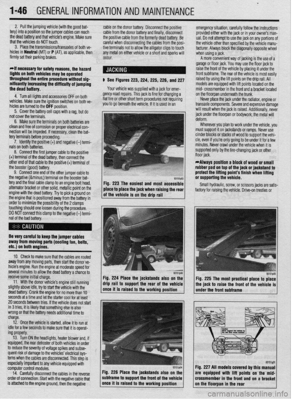
$ See Figures 223,224, 225,226, and 227
Your vehicle was supplied with a jack for emer-
gency road repairs. This jack is fine for changing a
flat tire or other short term procedures not requiring
you to go beneath the vehicle. If it is used in an emergency situation, carefully follow the instructions
provided either with the jack or in your owners man-
ual. Do not attempt to use the jack on any portions of
the vehicle other than specified by the vehicle manu-
facturer. Always block the diagonally opposite wheel
when using a jack.
A more convenient way of jacking is the use of a
garage or floor jack. You may use the floor jack to
raise the front of the vehicle by placing it under the
front subframe. The rear of the vehicle is most easily
raised by using the lift points on the drip rail. All
models are equipped with lift points located on the
mid- crossmember in the front and a bracket located
on the floorpan underneath the trunk.
Never place the jack under the radiator, engine or
transaxle components. Severe and expensive damage
will result when the jack is raised. Additionally, never
jack under the floorpan or
bodywork; the
metal will
Whenever you plan to work under the vehicle, you
must support it on jackstands or ramps. Never use
cinder blocks or stacks of wood to support the vehi-
cle, even if you’re only going to be under it for a few
minutes. Never crawl under the vehicle when it is
supported only by the tire-changing jack or other
*Always position a block of wood or small
rubber pad on top of the jack or jackstand to
protect the lifting point’s finish when lifting
or supporting the vehicle.
Small hydraulic, screw, or scissors jacks are satis-
factory for raising the vehicle. Drive-on trestles or
Be very careful to keep the jumper cables
away from moving parts (cooling fan, belts,
etc.) on both engines.
10. Check to make sure that the cables are routed
away from any moving parts, then start the donor ve-
hicle’s engine. Run the engine at moderate speed for
several minutes to allow the dead battery a chance to
receive some initial charge.
11. With the donor vehicle’s engine still running
slightly above idle, try to start the vehicle with the
dead battery. Crank the engine for no more than 10 &stands also on the
Fig. 225 The most practical place to place
front of the vehicle is
seconds at a time and let the starter cool for at least
20 seconds between tries. If the vehicle does not start
in 3 tries, it is likely thatsomething else is also
wrong or that the battery needs additional time to
charge.
12. Once the vehicle is started, allow it to run at
idle for a few seconds to make sure that it is operat-
ing properly.
13. Turn ON the headlights, heater blower and, if
equipped, the rear defroster of both vehicles in order
to reduce the severity of voltage spikes and subse-
quent risk of damage to the vehicles’ electrical sys-
tems when the cables are disconnected. This step is
especially important to any vehicle equipped with
computer control modules.
14. Carefully disconnect the cables in the’reverse
order of connection. Start with the negative cable that
is attached to the engine ground, then the negative Fig. 226 Place the jackstands also
subframe to support the front of the Fig. 227 All models covered by this
are equipped with lift points on t
crossmember in the front and on a
Page 46 of 408
GENERAL INFORMATION AND MAINTENANCE 1-47
ramps are also a handy and safe way to both raise l When the drive wheels are to remain on the
and support the vehicle. Be careful though, some ground, leave the vehicle in gear to help prevent it
ramps may be too steep to drive your vehicle onto
The following safety points cannot be overempha- from rolling.
without scraping the front bottom panels. Never sup-
sized:
l Always use jackstands to support the vehicle
port the vehicle on any suspension member (unless l Always block the opposite wheel or wheels to when you are working underneath. Place the stands
specifically instructed to do so by a repair manual) or
keep the vehicle from rolling off the jack. beneath the vehrcle’s jacking brackets Before climb-
by an underbody panel.
l When raising the front of the vehicle, firmly ap- ing underneath, rock the vehicle a bit to make sure it
ply the parking brake. is firmly supported.
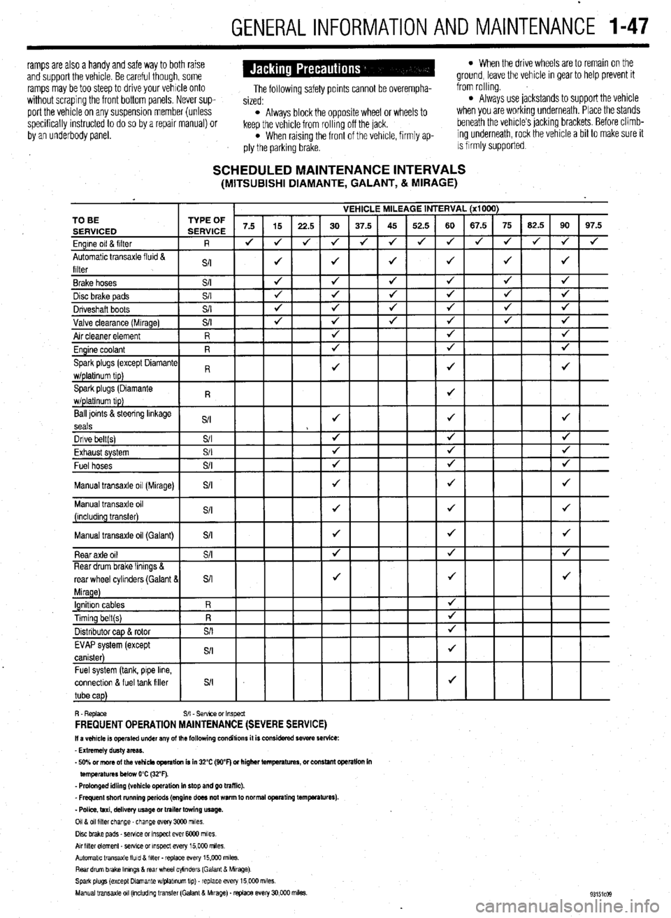
SCHEDULED MAINTENANCE INTERVALS (MITSUBISHI DIAMANTE, GALANT, & MIRAGE)
VEHICLE MILEAGE INTERVAL (x1000)
7.5 15
22.5 30 37.5 45 52.5 60 67.5 75 62.5 90 97.5
J J
J 4 J J 4 4 4 J J
J 4
4
J J J J 4 TO BE
Ball loints &steering linkage
S/I J J J
seals
Dnve belt(s) S/I 4 4 J
Fvha,,rt cvctom $/I
J J J LmI,..“w. “,YL”,‘. Fuel hoses
+
Manual transaxle oil (Galant)
connectlon & fuel tank filler
R. Replace S/I - Sefwce or Inspect FREQUENT OPERATION MAINTENANCE (SEVERE SERVICE) II a vehicle is operated under any of the following conditions it is considered severe service:
- Extremely dusty areas.
- 50% or more of the vehicle operation is in 32% (WF) or higher temperatures, or constant opsralion in
temperatures below 0% (32°F).
- Prolonged idling (vehicle operation in stop and go traffic).
_ Frequent short running periods (engine does not warm to normal operating temfwatures).
- Police, taxi, delivery usage or trailer towing usage.
0118 011 filter change-change every 3CQO miles.
Disc brake pads - sewce or Inspect ever 6COO miles
AN hlter element _ setwe or inspect every 15,000 miles.
Automatic transaxle lluld 8 filter . replace every 15,COO m&s.
Rear drum brake Ikmngs & rear wheel cylinders (Galant & Mirage)
Spark plugs (except Dlamante wlplabnum tip) - replace every 15,COO miles.
Manual transaxle 011 (mcludlng transfer (Galant & Mirage). replace every 30,000 miles.
Page 47 of 408
1-48 GENERALINFORMATIONAND MAINTENANCE
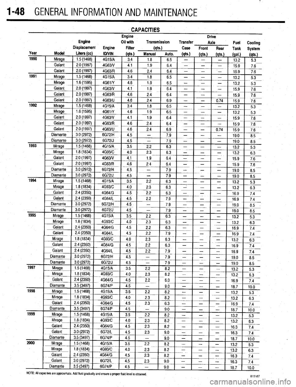
CAPACITIES Engine
Drive
Page 48 of 408
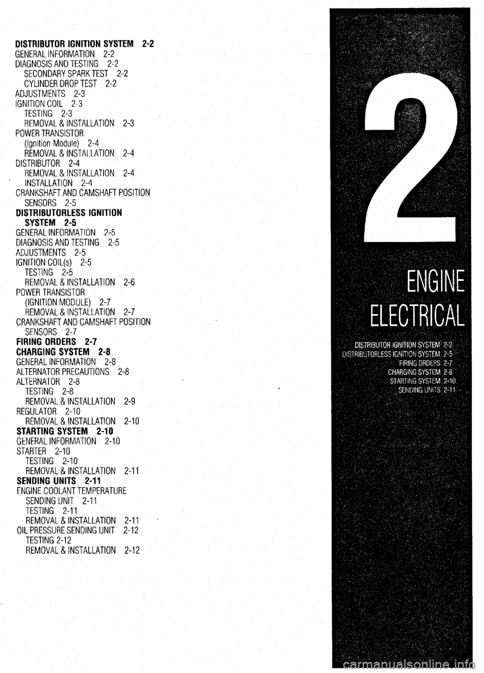
DISTRIBUTOR IGNITION SYSTEM
GENERALINFORMATION 2-2
DIAGNOSISANDTESTING 2-2
SECONDARYSPARKTEST 2-2
CYLINDERDROPTEST 2-2
ADJUSTMENTS 2-3
IGNITION COIL 2-3
TESTING 2-3
REMOVAL&INSTALLATION 2-3
POWERTRANSISTOR
(Ignition Module) 2-4
REMOVAL&INSTALLATION 2-4
DISTRIBUTOR 2-4
REMOVAL&INSTALLATION 2-4 2-2
INSTALLATION 2-4
CRANKSHAFTANDCAMSHAFTPOSITION
SENSORS 2-5
DISTRIBUTORLESS IGNITION
SYSTEM 2-5
GENERALINFORMATION 2-5
DIAGNOSISANDTESTING 2-5
ADJUSTMENTS 2-5
IGNITION COIL(s) 2-5
TESTING 2-5
REMOVAL&INSTALLATION 2-6
POWERTRANSISTOR
(IGNITION MODULE) 2-7
REMOVAL&INSTALLATION 2-7
CRANKSHAFTANDCAMSHAFTPOSITION
SENSORS 2-7
FIRING ORDERS 2-7
CHARGING SYSTEM 2-8
GENERALINFORMATION 2-8
ALTERNATORPRECAUTIONS 2-8
ALTERNATOR 2-8
TESTING 2-8 I
REMOVAL&INSTALLATION 2-9
REGULATOR 2-10
REMOVAL&INSTALLATION 2-10
STARTING SYSTEM 2-10
GENERALINFORMATION 2-10
STARTER 2-10
TESTING 2-10
REMOVAL&INSTALLATION 2-11
SENDING UNITS 2-11
ENGINECOOLANTTEMPERATURE
SENDING UNIT 2-11
TESTING 2-11
REMOVAL&INSTALLATION 2-11
OIL PRESSURESENDING UNIT 2-12
TESTING 2-12
REMOVAL&INSTALLATION 2-12
Page 49 of 408
.~ P.X I_ - “, .- I .-., IS ” .~.I .r
2-2 ENGINE ELECTRICAL
nn
ity and trouble: shooting electrical circuits,
please refer to Section 6 of this manual.
I
The ignition system on the 1.5L, 1993-96 1.8L,
2.OL SOHC, 1994-98 2.4L SOHC, 3.OL SOHC, and
3.5L engines uses a pointless type distributor, whose
advance mechanism is controlled by the Engine Con-
trol Unit (ECU). On the 1.5L, 1.8L, 2.4L and 3.5L en-
gines, the distributor houses a built in ignition coil
and ignition power transistor. The 2.8L SOHC and
3.OL SOHC engines utilize a separate coil and tran-
sister assemblv.
When the ignition switch is turned ON, battery
voltage is applied to the ignition coil primary winding.
As the shaft of the distributor rotates, signals are
transmitted from the oowertrain control module to the
9105zp11 Fig. 1 This spark tester looks iust like a
Fiu. 2 This spark tester has an adjustable
spark plug, attach the clip to ground and air-gap for measuring spark strength and
crank the engine to check for spark testing different voltage ignition systems
.
ignition power trar rsistor. These signals activate the
power transistor to cause ignition coil primary wind-
ing current flow from the ignition coil negative termi-
nal through the power transistor to ground repeatedly.
This interruption induces high voltage in the ignition
coil secondarv windinas, which is diverted throuah
the distributor, spark plug cable and spark plug 6
ground, thus causing ignition in each cylinder.
I
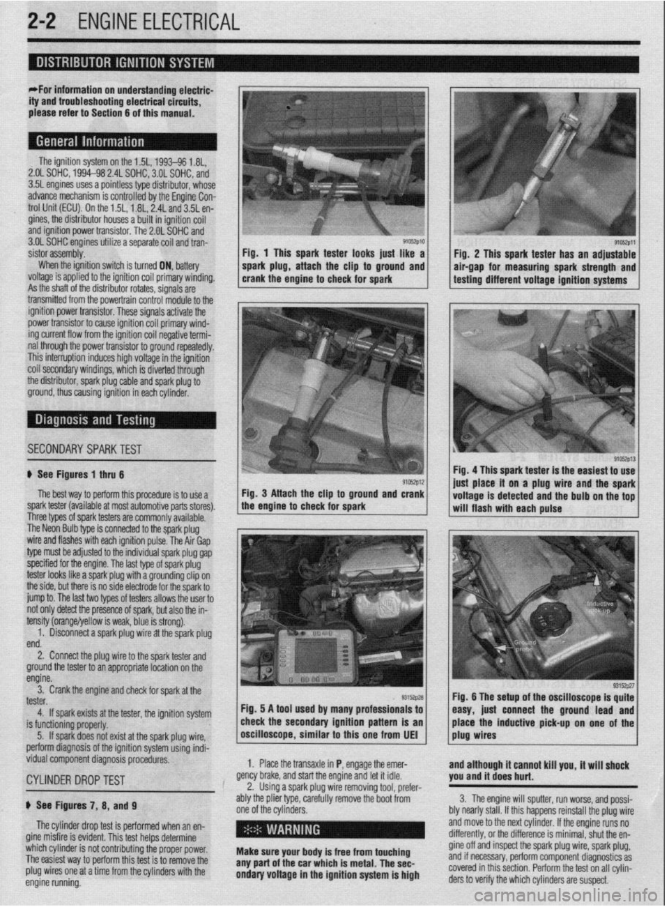
SECONDARYSPARKTEST l;h.4-
! ,L ".~
'$ >,%
If See Figures 1 thru 6
91rJszp12 Fig. 4 This spark tester is the easiest to use
iust alace it on a plug wire and the spark
The best way to perform this procedure is to use a Fig. 3 Attach the clip to ground and crank
spark tester (available at most automotive parts stores). the engine to check for spark
I I voltage is detected and the bulb on the tof
-. will flash with each pulse
I nree types ot spark testers are commonly available.
The Neon Bulb type is connected to the spark plug
wire and flashes with each ignition pulse. The Air Gap
type must be adjusted to the individual spark plug gap
specified for the engine. The last type of spark plug
tester looks like a spark plug with a grounding clip on
the side, but there is no side electrode for the spark to
jump to. The last two types of testers allows the user to
not only detect the presence of spark, but also the in-
tensity (orange/yellow is weak, blue is strong).
1. Disconnect a spark plug wire at the spark plug
end.
2. Connect the plug wire to the spark tester and
ground the tester to an appropriate location on the
engine.
3. Crank the engine and check for spark at the
tester.
4. If spark exists at the tester, the ignition system
is functioning properly.
5. If spark does not exist at the spark plug wire,
perform diagnosis of the ignition system using indi-
vidual component diagnosis procedures,
CYLINDER DROPTEST
p See Figures 7, 8, and 9
The cylinder drop test is performed when an en-
gine misfire is evident. This test helps determine
which cylinder is not contributing the proper power.
The easiest way to perform this test is to remove the
plug wires one at a time from the cylinders with the
engine running. 1. Place the transaxle in P, engage the emer-
gency brake, and start the engine and let it idle.
2. Using a spark plug wire removing tool, prefer-
ably the plier type, carefully remove the boot from
one of the cylinders.
i ’
Make sure your body is free from touching
any part of the car which is metal. The sec-
ondary voltage in the ignition system is high and although it cannot kill you, it will shock
you and it does hurt.
3. The engine will sputter, run worse, and possi-
bly nearly stall. If this happens reinstall the plug wire
and move to the next cylinder. If the engine runs no
differently, or the difference is minimal, shut the en-
gine off and inspect the spark plug wire, spark plug,
and if necessary, perform component diagnostics as
covered in this section. Perform the test on all cylin-
ders to verify the which cylinders are suspect.
Page 50 of 408
ENGINEELECTRICAL 2-3
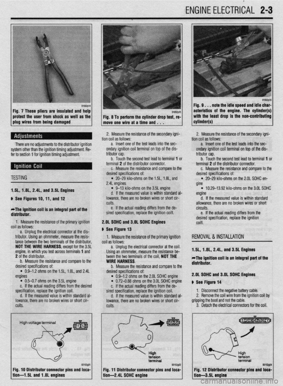
91c6zp16 Fig. 9. . . note the idle speed and idle char-
acteristics of the engine. The cylinder(s)
with the least drag is the non-contributing
cyltnder(s) -
1
There are no adjustments to the distributor ignition
system other than the ignition timing adjustment. Re-
fer to section 1 for ignition timing adjustment.
TESTING
1.5L, 1.8L, 2.41, and 3.51 Englnes
u See Figures 10, 11, and 12
*The ignition cog is an integral part of the
distributor.
1. Measure the resistance of the primary ignition
coil as follows:
a. Unplug the electrical connector at the dis-
tributor. Using an ohmmeter, measure the resis-
tance between the two terminals of the distributor,
NOT THE WIRE HARNESS, except for the 3.5L
engine, in which you test across terminals 1 and
2 of the distributor.
b. Measure the resistance and compare to the
desired specifications of:
l 0.9-1.2 ohms on the 1.5L, 1.8L, and 2.4L
engines
l 0.5-0.7 ohms on the 35L engine
c. If the actual reading differs from the desired
specification, replace the ignition coil.
d. If the measured value is within standard al-
lowance, there are no broken wires or short cir-
cuits. 2. Measure the resistance of the secondary igni-
desired specifications of: tion coil as follows:
l 21329 kilo-ohms on the 1.5L, 1.8L, and
2.4L engines a. Insert one of the test leads into the sec-
ondary ignition coil terminal on top of the dis-
l 9-13 kilo-ohms on the 3.5L engine tributor cap.
d. If the measured value is within standard al- b. Touch the second test lead to terminal 1 or
terminal 2 of the distributor connector.
lowance, there are no broken wires or short cir-
cuits. c. Measure the resistance and comnare to the
e. If the actual reading differs from the de
sired specification, replace the ignition coi!l.
2.OL SOHC and 3.OL SOHC Engines
# See Figure 13
1. Measure the resistance of the primary ignition
coil as follows:
a. Unplug the electrical connector at the coil.
Using an ohmmeter, measure the resistance be-
tween the two terminals of the coil, NOT THE
WIRE HARNESS.
b. Measure the resistance and compare to the
desired specifications of:
l 0.9-1.2 ohms on the 2.OL SOHC engine l 0.72-0.88 ohms on the 3.OL SOHC engine
c. If the actual reading differs from the de-
sired specification, replace the ignition coil.
d. If the measured value is within standard al-
lowance, there are no broken wires or short cir-
cuits. 2.
desired specifications of: Measure the resistance of the secondary igni-
tion coil as follows:
l 20-29 kilo-ohms on the 2.OL SOHC en-
gine a. Insert one of the test leads into the sec-
ondary ignition coil terminal on top of the dis-
l 10.29-13.92 kilo-ohms on the 3.01 SOHC tributor cap.
engine b. Touch the second test lead to terminal 1 or
terminal 2 of the distributor connector.
d. If the measured value is within standard
allowance, there are no broken wires or short c. Measure the resistance and comoare to the
circuits.
e. If the actual reading differs from the
desired specification, replace the ignition
coi!l.
REMOVAL&INSTALLATION
1.5L, 1.8L, 2.4L, and 3.5L Engines
*The ignition coil is an tntegral part of the
distributor.
2.OL SOHC and 3.OL SDHC Engines
u See Figure 14
1. Disconnect the negative battery cable.
2. Remove the coil wire from the ignition coil by
gripping the boot and not the cable.
3. Detach the electrical connectors for the coil.
High voltage terminal -r
I Q3 ‘I u,
/ - Blm/ I L tflgn
tension
terminal
,
3=%@ @l&M Fig. IO Distributor connector pins and loca-
Fig. 11 Distributor connector pins and loca- Fig. 12 Dlstrfbufor connector plus and loca-
tiou-l.LL and 1.8L engines
lion-2.4L SOHC engtne tio&.5L engine
Page 51 of 408
2-4 ENGINEELECTRICAL
2. Install the distributor in the engine so the rotor
is aligned with the matchmark on the housing and the
housing is aligned with the matchmark on the engine.
4.‘ Remove the retaining screws and coil from en-
gine.
5. Installation is the reverse of the removal proce-
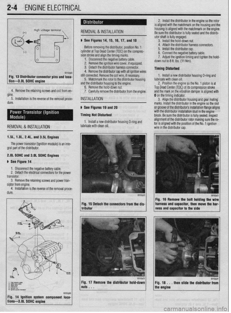
dure. Before removing the distributor, position No. 1
‘cylinder at Top Dead Center (TDC) on the compres-
sion stroke and align the timing marks.
1. Disconnect the negative battery cable.
2. Remove the ignition wire cover, if equipped.
3. Detach the distributor harness connector.
4. Remove the distributor cap with all ignition wires
still connected. Remove the coil wire, if necessary.
5. Matchmark the rotor to the distributor housing
and the distributor housing to the engine.
6. Remove the hold-down nut.
7. Carefully remove the distributor from the engine.
INSTALLATION
6 See Figures 19 and 2g
Timing Not Disturbed
1, Install a new distributor housing O-ring and 4. Attach the distributor harness connectors.
5. Install the distributor cap.
6. Connect the negative battery cable.
7. Adjust the ignition timing and tighten the hold-
down nut to 6 ft. Ibs. (11 Nm).
Timing Dlsturbed
1. Install a new distributor housing O-ring and
lubricate with clean oil.
2. Position the engine so the No. 1 piston is at
Top Dead Center (TDC) of its compression stroke
and the mark on the vibration damper is aligned with
REMOVALS& INSTALLATION lubricate with clean oil. 0 on the timing indicator.
3. Align the distributor housing and gear mating
marks. Install the distributor in the engine so the slot
or groove of the distributor’s installation flange aligns
with the distributor installation stud in the engine
block. Be sure the distributor is fully seated. Inspect
alignment of the distributor rotor making sure the ro- tnr ic dinnnd with thn qn,c$nn of the Nn innitinn
ISL, 1 AIL, 2.4L, and 3.5L Engines
The power transistor (ignition module) is an inte-
gral part of the distributor.
2.gL SDHC and 3.OL SOHC Engines
# See Figure 14
1 x Disconnect the negative battery cable.
Remove the retaining screws and power tran-
Detach the connectors from the dis- Fig. 16 Remove the bolt holding the wire
harness and capacitor, then move the har-
ness and capacitor to the side
Fig. 18 . . . then slide the distributor from
the engine
/ tion’s-3.gL SOHC engine g3is~@ 1 Fig 14 Ignition system component loca-
Page 52 of 408
ENGlNEELECTRliAL 2-5
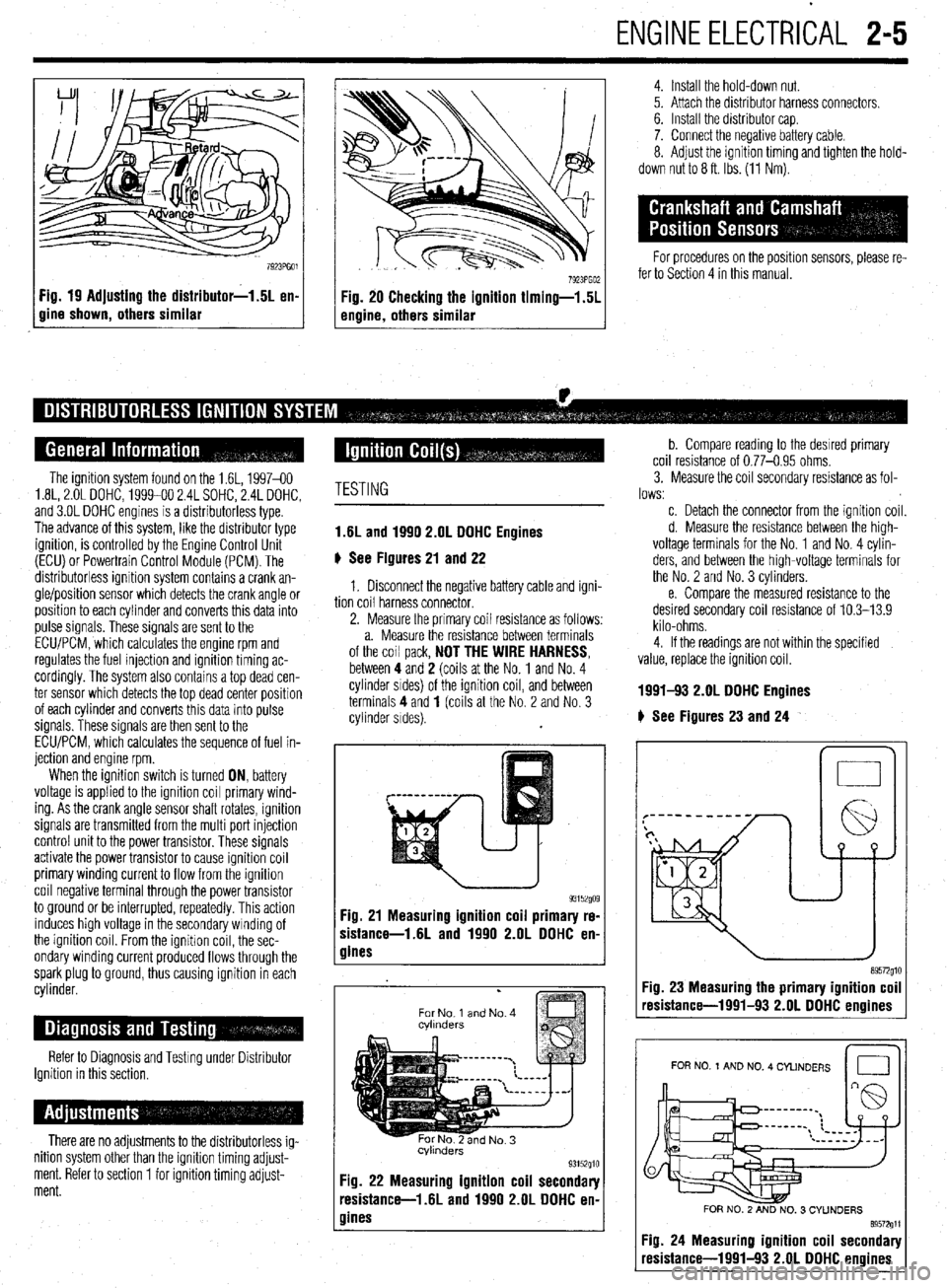
Fig. 19 Adjusting the distributor-1.5L en-
gine shown, others similar
4. Install the hold-down nut.
5. Attach the distributor harness connectors.
6. Install the distributor cap.
7. Connect the negative battery cable.
8. Adjust the ignition timing and tighten the hold-
down nut to 8 ft. Ibs. (11 Nm).
For procedures on the position sensors, please re-
fer to Section 4 in this manual.
The ignition system found on the 1.6L, 1997-60
1.8L, 2.OL DOHC, 1999-00 2.4L SOHC, 2.4L DOHC,
and 3.OL DOHC engines is a distributorless type.
The advance of this system, like the distributor type
ignition, is controlled by the Engine Control Unit
(ECU) or Powertrain Control Module (PCM). The
distributorless ignition system contains a crank an-
gle/position sensor which detects the crank angle or
position to each cylinder and converts this data into
pulse signals. These signals are sent to the
ECLVPCM, which calculates the engine rpm and
regulates the fuel injection and ignition timing ac-
cordingly. The system also contains a top dead cen-
ter sensor which detects the top dead center position
of each cylinder and converts this data into pulse
signals. These signals are then sent to the
ECU/PCM, which calculates the sequence of fuel in-
jection and engine rpm.
When the ignition switch is turned ON, battery
voltage is applied to the ignition coil primary wind-
ing. As the crank angle sensor shaft rotates, ignition
signals are transmitted from the multi port injection
control unit to the power transistor. These signals
activate the power transistor to cause ignition coil
primary winding current to flow from the ignition
coil negative terminal through the power transistor
to ground or be interrupted, repeatedly. This action
induces high voltage in the secondary winding of
the ignition coil. From the ignitron coil, the sec-
ondary winding current produced flows through the
spark plug to ground, thus causing ignition in each
cylinder.
Refer to Diagnosis and Testing under Distributor
Ignition in this section,
There are no adjustments to the distributorless ig-
nition system other than the ignition timing adjust-
ment. Refer to section 1 for ignition timing adjust-
ment.
TESTING
1.6L and 1990 2.OL DOHC Engines
6 See Figures 21 and 22
1. Disconnect the negative battery cable and igni-
tion coil harness connector.
2. Measure the primary coil resistance as follows:
a. Measure the resistance between terminals
of the coil pack,
NOT THE WIRE HARNESS, between 4 and 2 (coils at the No. 1 and No. 4
cylinder srdes) of the ignition coil, and between
terminals 4 and
1 (coils at the No. 2 and No. 3
cylinder sides).
93152go9 Fig. 21 Measuring ignition coil primary re-
sistance-1.6L and 1990 2.OL DDHC en-
gines
.
For No 1 and No. 4
cvlmders
Fig. 22 Measuring ignition coil secondary
resistance-l .6L and 1990 2.OL DOHC en-
gines
b. Compare reading to the desrred primary
coil resistance of 0.77-0.95 ohms.
3. Measure the coil secondary resistance as fol-
lows:
c. Detach the connector from the ignition coil.
d. Measure the resistance between the high-
voltage terminals for the No. 1 and No. 4 cylin-
ders, and between the high-voltage terminals for
the No. 2 and No. 3 cylinders.
e. Compare the measured resistance to the
desired secondary coil resistance of 10.3-13.9
kilo-ohms.
4. If the readings are not within the specified
value, replace the ignition coil.
1991-!I3 2.OL DDHC Engines
# See Figures 23 and 24
n 0
Fig. 23 Measuring the primary ignition coil
resistance-1991-93 2.OL DOHC enoines
I I
FOR NO 1 AND NO. 4 CYLINDERS
Id
FOR NO. 2 AND NO. 3 CYUNDERS
89572611
Fig. 24 Measuring ignition coil secondary
resistance-1991-93 2.OL DOHC engines