1900 MITSUBISHI DIAMANTE wheel
[x] Cancel search: wheelPage 115 of 408
3-54 ENGINEANDENGINEOVERHALJL
from the, access may be possible (though a little
awkward) to measure the camshaft lobes using a mi-
crometer
In any case, two measurements are necessary for
each lobe. Measurement Y or the total LOBE HEIGHT
and measurement X or the total LOBE WIDTH. To
find the lobe lift, you simply subtract X from Y (sub-
tract the width from the height).
Note each measurement, then make your calcula-
tion to determine the lift. Note the final results and re-
peat the process on the remaining camshaft lobes.
Finally, you should compare your results to the spec-
ifications charts and decide if a new camshaft is in
your future.
REMOVAL &INSTALLATION
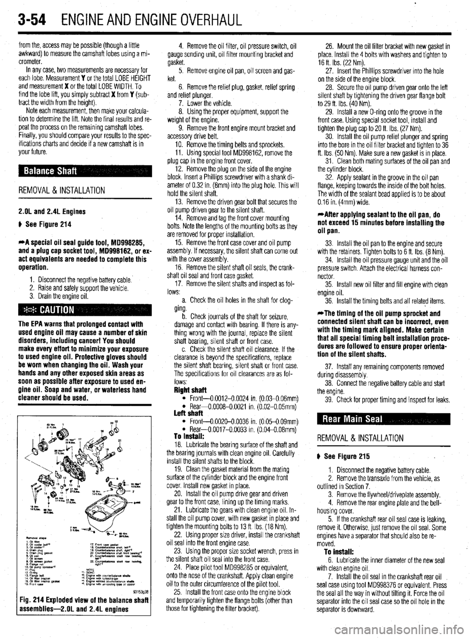
2.OL and 2.4L Engines
p See Figure 214
*A special oil seal guide tool, 18998285,
and a plug cap socket tool, MD998182, or ex-
act equivalents are needed to complete this
operation.
1. Disconnect the negative battery cable.
2. Raise and safely support the vehicle.
3. Drain the engine oil.
The EPA warns that prolonged contact with
used engine oil may cause a number of skin
disorders, including cancer! You should
make every effort to minimize your exposure
to used engine oil. Protective gloves should
be worn when changing the oil. Wash your
hands and any other exposed skin areas as
soon as possible after exposure to used en-
gine oil. Soap and water, or waterless hand
cleaner should be used.
93153g3
:ig. 214 Exploded view of the balance shaf
assemblies-2.01 and 2.4L enoines
4. Remove the oil filter, oil pressure switch, oil
gauge sending unit, oil filter mounting bracket and
gasket.
5. Remove engine oil pan, oil screen and gas-
ket.
6. Remove the relief plug, gasket, relief spring
and relref plunger.
7. Lower the vehicle.
8. Using the proper equipment, support the
weight of the engine.
9. Remove the front engine mount bracket and
accessory drive belt,
10. Remove the timing belts and sprockets.
11. Using special tool MD998162, remove the
plug cap in the engine front cover.
12. Remove the plug on the side of the engine
block. Insert a Phillips screwdriver with a shank di-
ameter of 0.32 in. (8mm) into the plug hole. This will
hold the silent shaft.
13. Remove the driven gear bolt that secures the
oil pump driven gear to the silent shaft.
14. Remove and tag the front cover mounting
bolts. Note the lengths of the mounting bolts as they
are removed for proper installation.
15. Remove the front case cover and oil pump
assembly. If necessary, the silent shaft can come out
with the cover assembly.
16. Remove the silent shaft oil seals, the crank-
shaft oil seal and front case gasket
17. Remove the silent shafts and inspect as fol-
lows:
a. Check the oil holes in the shaft for clog-
ging.
b. Check journals of the shaft for seizure,
damage and contact with bearing. If there is any-
thing wrong with the journal, replace the silent
shaft bearing, silent shaft or front case.
c. Check the silent shaft oil clearance. If the
clearance is beyond the specifications, replace
the silent shaft bearing, silent shaft or front case.
The specifications for oil clearances are as fol-
lows
Right shaft l Front-0.0012-0.0024 in. (0.030.06mml l Rear+0.0008-0.0021 in. (6.02-O 05mm) Left shaft l Front-0.002&0.0036 in. (0.05-0.09mm) l Rear-O.0017-O.0033 in. (0.04-0.08mm) To install: 18. Lubricate the bearing surface of the shaft and
the bearing journals with clean engine oil. Carefully
install the silent shafts to the block.
19. Clean the gasket material from the mating
surface of the cylinder block and the engine front
cover. Install new gasket in place.
20. Install the oil pump drive gear and driven
gear to the front case, lining up the timing marks.
21. Lubricate the gears with clean engine oil. In-
stall the oil pump cover, with new gasket in place and
tighten the mounting bolts to 13 ft. Ibs. (18 Nm).
22. Using proper size driver, install the crankshaft
oil seal into the front engine case.
23. Using the proper size socket wrench, press in
the silent shaft oil seal into the front case.
24. Place pilot tool MD998285 or equivalent,
onto the nose of the crankshaft. Apply clean engine
oil to the outer circumference of the pilot tool.
25. Install the front case onto the engine block
and temporarily tighten the flange bolts (other than
those for tightening the filter bracket). 26. Mount the oil filter bracket with new gasket in
place. Install the 4 bolts with washers and tighten to
16 ft Ibs. (22 Nm).
27. Insert the Phillips screwdriver into the hole
on the side of the engine block.
28. Secure the oil pump driven gear onto the left
silent shaft by tightening the driven gear flange bolt
to 29 ft. Ibs. (40 Nm).
29. Install a new O-ring onto the groove in the
front case. Using special socket tool, install and
tighten the plug cap to 20 ft. Ibs (27 Nm).
30. Install the oil pump relief plunger and spring
into the bore in the oil filter bracket and tighten to 36
ft. Ibs. (50 Nm). Make sure a new gasket is in place.
31. Clean both mating surfaces of the oil pan and
the cylinder block.
32. Apply sealant in the groove in the oil pan
flange, keeping towards the inside of the bolt holes.
The width of the sealant bead applied is to be about
0.16 in. (4mm) wide.
*After applying sealant to the oil pan, do
not exceed 15 minutes before installing the
oil pan.
33. Install the oil pan to the engine and secure
with the retainers. Tighten bolts to 6 ft. Ibs. (8 Nm).
34. Install the oil pressure gauge unit and the oil
pressure switch. Attach the electrical harness con-
nector
35. Install new oil filter and fill engine with clean
engine oil.
36. Install the timing belts and all related items,
*The timing of the oil pump sprocket and
connected silent shaft can be incorrect, even
with the timing mark aligned. Make certain
that all special timing belt installation proce-
dures are followed to ensure proper orienta-
tion of the silent shafts.
37. Install any remaining components removed
during disassembly.
38. Connect the negative battery cable and start
the engine.
39. Check for proper timing and inspect for leaks.
REMOVAL &INSTALLATION
p See Figure 215
1. Disconnect the negative battery cable.
2. Remove the transaxle from the vehicle, as
outlined in Section 7.
3. Remove the flywheel/driveplate assembly.
4. Remove the rear engine plate and the bell-
housing cover.
5. If the crankshaft rear oil seal case is leaking,
remove it. Otherwise, just remove the oil seal. Some
engines have a separator that should also be re-
moved.
To install: 6. Lubricate the inner diameter of the new seal
with clean engine oil.
7. Install the oil seal in the crankshaft rear oil
seal case using tool MD998376 or equivalent. Press
the seal all the way in without tilting it. Force the oil
separator into the oil seal case so the oil hole in the
separator is downward.
Page 116 of 408
ENGINEANDENGINEOVERHAUL 3-55
8. Run a bead of sealer along any seams be-
tween the seal case and block. Install the seal case
with a new gasket.
9. Install the flywheel/driveplate and transaxle.
10. Connect the negative battery cable and check
for leaks.
11. Adjust oil level as necessary.
REMOVAL &INSTALLATION To lnstell:
7. Coat the threads of the driveplate/flywheel re-
taining bolts with thread locking compound.
8. Position the driveplatelflywheel on the crank-
shaft flange.
9. On automatic transaxle equipped models, in-
stall the driveplate adapter.
10. Install and tighten the bolts, in a alternating
star pattern, to the following specifications:
l 1.5L engine: 98 ft. Ibs. (135 Nm) l 1.6L, 2.01 and 2.4L engines: 94-101 ft.
Ibs. (130-140 Nm)
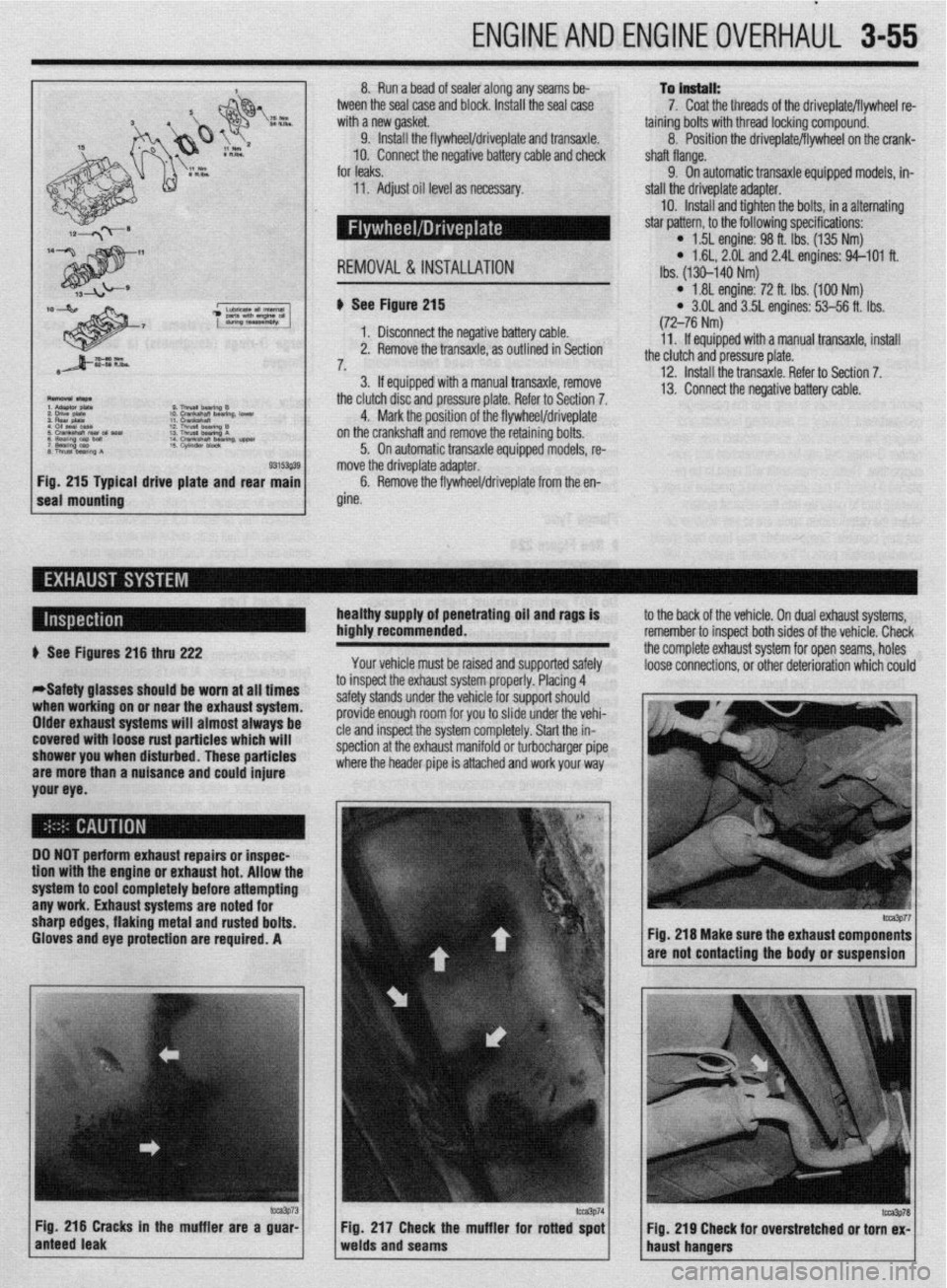
al drive plate and rear b See Figure 215
1. Disconnect the negative battery cable.
2. Remove the transaxle, as outlined in Section
7,
3. If equipped with a manual transaxle, remove
the clutch disc and pressure plate. Refer to Section 7.
4. Mark the position of the flywheel/driveplate
on the crankshaft and remove the retaining bolts.
5. On automatic transaxle equipped models, re-
move the driveplate adapter.
6. Remove the flywheel/driveplate from the en-
gine.
l 1.81 engine: 72 ft. Ibs. (100 Nm) l 3.OL and 3.5L engines: 53-56 ft. Ibs.
(72-76 Nm)
11. If equipped with a manual transaxle, install
the clutch and pressure plate.
12. Install the transaxle. Refer to Section 7.
13. Connect the negative battery cable.
healthy supply of penetrating oil and rags is
highly recommended.
Your vehicle must be raised and supported safely to the back of the vehicle. On dual exhaust systems,
remember to insoect both sides of the vehicle. Check
the complete exhaust system for open seams, holes
loose connections, or other deterioration which could + See Figures 216 thru 222
*Safety glasses should be worn at all times
when working on or near the exhaust system.
Older exhaust systems will almost always be
covered with loose rust particles which will
shower you when disturbed. These particles
are more than a nuisance and could injure
your eye. to inspect the exhaust system properly. Placing 4
safety stands under the vehicle for support should
provide enough room for you to slide under the vehi-
cle and inspect the system completely. Start the in-
spection at the exhaust manifold or turbocharger pipe
where the header pipe is attached and work your way
DO NOT perform exhaust repairs or inspec-
tion wtth the engine or exhaust hot. Allow thr
system to cool completely before attempting
any work. Exhaust systems are noted for
sharp edges, flaking metal and rusted bolts.
Gloves and eye protection are required. A
m3p73 Fig. 216 Cracks in the muffler are a guar-
anteed leak Fig 217 Check the muffler for rotted spot
Fig. 219 Cheek for overstretched or torn ex-
welds and seams
haust hangers
fm3p77 Fig. 216 Make sure the exhaust components
are not contacting the body or suspension
lcca3P78
Page 120 of 408
ENGINEAND ENGINEOVERHAUL 3-59
Most of the cleaning process can be carried out
with common hand tools and readily available sol-
vents or solutions. Carbon deposits can be chipped
away using a hammer and a hard wooden chisel. Old
gasket material and varnish or sludge can usually be
removed using a scraper and/or cleaning solvent. Ex-
tremely stubborn deposits may require the use of a
power drill wrth a wire brush. If using a wire brush,
use extreme care around any critical machined sur-
faces (such as the gasket surfaces, bearing saddles,
cylinder bores, etc.). USE OF A WIRE BRUSH IS NOT
RECOMMENDED ON ANY ALUMINUM COMPO-
NENTS Always follow any safety recommendations
given by the manufacturer of the tool and/or solvent.
You should always wear eye protection during any
cleaning process involvrng scraping, chipping or
spraying of solvents.
An alternative to the mess and hassle of cleaning
the parts yourself is to drop them off at a local garage
or machine shop. They will, more than likely, have
the necessary equrpment to properly clean all of the
parts for a nominal fee.
Always wear eye protection during any clean-
ing process involving scraping, chipping or
spraying of solvents.
Remove any oil galley plugs, freeze plugs and/or
pressed-in bearings and carefully wash and degrease
all of the engine components including the fasteners
and bolts. Small parts such as the valves, springs,
etc., should be placed in a metal basket and allowed
to soak. Use pipe cleaner type brushes, and clean all
passageways in the components. Use a ring ex-
pander and remove the rings from the pistons. Clean
the piston ring grooves with a special tool or a piece
of broken ring Scrape the carbon off of the top of the
piston. You should never use a wire brush on the
pistons. After preparing all of the piston assemblies
in this manner, wash and degrease them again.
Use extreme care when cleaning around the
cylinder head valve seats. A mistake or slip
may cost you a new seat.
When cleaning the cylinder head, remove carbon
from the combustron chamber with the valves in-
stalled. This will avoid damaging the valve seats.
:ig. 234 Drill out the damaged threads with
he specified size bit. Be sure to drill corn.
rletely through the hole or to the bottom oi
I blind hole REPAIRING DAMAGEDTHREADS
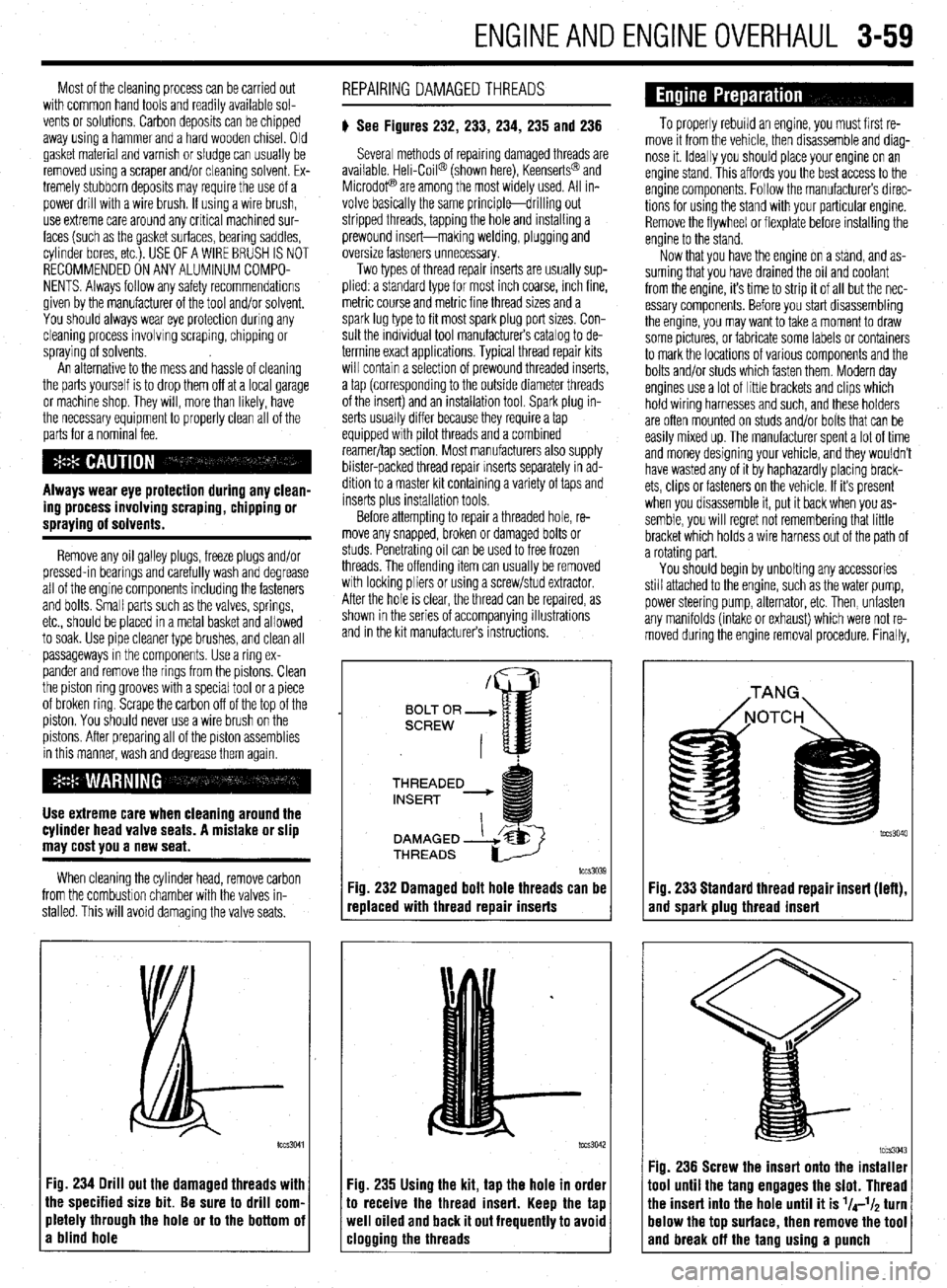
# See Figures 232, 233, 234, 235 and 236
Several methods of repairing damaged threads are
available Heli-Coil@ (shown here), Keenserts@ and
Microdop are among the most widely used. All in-
volve basically the same principle-drilling out
stripped threads, tapping the hole and installing a
prewound insert-making welding, plugging and
oversize fasteners unnecessary.
Two types of thread repair inserts are usually sup-
plied: a standard type for most inch coarse, rnch fine,
metric course and metrrc fine thread sizes and a
spark lug type to fit most spark plug port sizes. Con-
sult the individual tool manufacturers catalog to de-
termine exact applications. Typical thread repair kits
will contain a selection of prewound threaded inserts,
a tap (corresponding to the outside diameter threads
of the insert) and an installation tool. Spark plug in-
serts usually differ because they require a tap
equipped wrth pilot threads and a combined
reamer/tap section. Most manufacturers also supply
blister-packed thread repair Inserts separately in ad-
dition to a master kit containing a variety of taps and
inserts plus installation tools
Before attempting to repair a threaded hole, re-
move any snapped, broken or damaged bolts or
studs. Penetrating oil can be used to free frozen
threads. The offending item can usually be removed
with locking pliers or using a screw/stud extractor.
After the hole is clear, the thread can be reparred, as
shown in the series of accompanying illustrations
and in the krt manufacturers instructions.
THREADED
lCCS3039
replaced with thread repair inserts
:ig. 235 Using the kit, tap the hole in order
o receive the thread insert. Keep the tap
veil oiled and back it out frequently to avoid
:logging the threads
To properly rebuild an engine, you must first re-
move it from the vehicle, then disassemble and diag-
nose it. Ideally you should place your engine on an
engine stand. This affords you the best access to the
engine components. Follow the manufacturers direc-
tions for using the stand with your particular engine.
Remove the flywheel or flexplate before installing the
engine to the stand.
Now that you have the engine on a stand, and as-
suming that you have drained the oil and coolant
from the engine, it’s time to strip it of all but the nec-
essary components. Before you start disassembling
the engine, you may want to take a moment to draw
some pictures, or fabricate some labels or containers
to mark the locations of various components and the
bolts and/or studs which fasten them. Modern day
engines use a lot of little brackets and clips which
hold wiring harnesses and such, and these holders
are often mounted on studs and/or bolts that can be
easily mixed up. The manufacturer spent a lot of time
and money designing your vehicle, and they wouldn’t
have wasted any of it by haphazardly placing brack-
ets, clips or fasteners on the vehicle. If it’s present
when you disassemble it, put it back when you as-
semble, you will regret not remembering that little
bracket which holds a wire harness out of the path of
a rotating part.
You should begin by unbolting any accessories
still attached to the engine, such as the water pump,
power steering pump, alternator, etc. Then, unfasten
any manifolds (intake or exhaust) which were not re-
moved during the engine removal procedure. Finally,
Fig. 233 Standard thread repair insert (left),
and spark plug thread insert
im3043 Fig. 236 Screw the insert onto the installer
1001 until the tang engages the slot. Thread
‘he insert into the hole until it is l/4-l/~ turn
lelow the top surface, then remove the tool
and break off the tano usina a uunch
Page 126 of 408
I)
ENGINEANDENGINEOVERHAUL 3-65
10. Install the camshaft(s), rockers, shafts and
any other components that were removed for disas-
sembly.
GENERAL INFORMATION ways number 1. However, depending on the engine
placement, the front of the engine could either be the
flywheel or damper/pulley end. Generally the front of
the engine faces the front of the vehicle. Use a num-
ber punch or scribe and also mark the main bearing
caps from front to rear with the front most cap being
number 1 (if there are five caps, mark them 1 through
5, front to rear).
A thorough overhaul or rebuild of an engine block
would include replacing the pistons, rings, bearings,
timing belt/chain assembly and oil pump. For OHV
engines also include a new camshaft and lifters. The
block would then have the cylinders bored and honed
oversize (or if using removable cylinder sleeves, new
sleeves installed) and the crankshaft would be cut
undersize to provide new wearing surfaces and per-
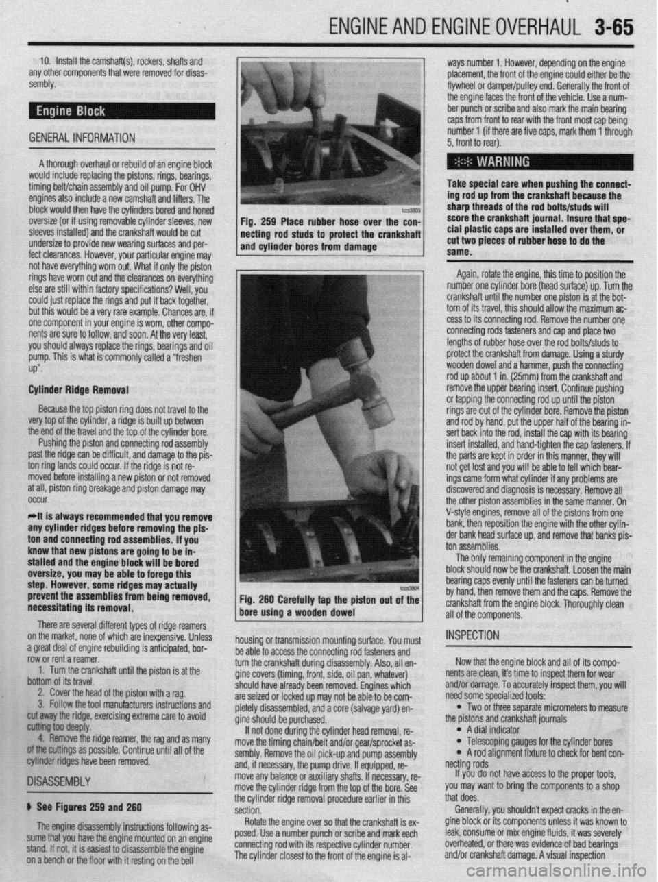
feet clearances. However, your particular engine may Take special care when pushing the connect-
ing rod up from the crankshaft because the
sharp threads of the rod bolts/studs will
score the crankshaft journal. Insure that spe-
cial plastic caps are installed over them, or
cut two pieces of rubber hose to do the
same.
Again, rotate the engine, this time to position the
number one cylinder bore (head surface) up. Turn the
crankshaft until the number one piston is at the bot-
tom of its travel, this should allow the maximum ac-
cess to its connecting rod. Remove the number one
connecting rods fasteners and cap and place two
lengths of rubber hose over the rod bolts/studs to
protect the crankshaft from damage. Using a sturdy
wooden dowel and a hammer, push the connecting
rod up about 1 in. (25mm) from the crankshaft and
remove the upper bearing insert. Continue pushing
or tapping the connecting rod up until the piston
rings are out of the cylinder bore. Remove the piston
and rod by hand, put the upper half of the bearing in-
sert back into the rod, install the cap with its bearing
insert installed, and hand-tighten the cap fasteners. If
the parts are kept in order in this manner, they will
not get lost and you will be able to tell which bear-
ings came form what cylinder if any problems are
discovered and diagnosis is necessary. Remove all
the other piston assemblies in the same manner. On
V-style engines, remove all of the pistons from one
bank, then reposition the engine with the other cylin-
der bank head surface up, and remove that banks nis-
prevent the assemblies from being removed,
necessitating its removal. Fig. 260 Carefully tap the piston out of the
bore using a wooden dowel
There are several different types of ridge reamers
on the market, none of which are inexpensive, Unless
.3 “me.+ ,-ins, rdnnn;nn mh~lil.-linn ;I nn+:n:nnL.* l.^W
a ylwx “Gal “I cllylllc Ir;““ll”llly 13 dllLILlpxC”, ““I- row or rent a reamer.
1. Turn the crankshaft until the piston is at the
bottom of its travel.
2. Cover the head of the piston with a rag.
3. Follow the tool manufacturers instructions and housing or transmission mounting surface. You must
1 as many
II of the
~1SA~E~BLY
b See Figures 259 and 260
The engine disassembly instructions following as-
sume that you have the engine mounted on an engine
stand. If not, it is easiest to disassemble the engine
on a bench or the floor with it resting on the bell be able to access the connecting rod fasteners and
turn the crankshaft during disassembly. Also, all en-
gine covers (timing, front, side, oil pan, whatever)
should
are sei2
nletelv have already been removed. Engines which
,ed or locked up may not be able to be com-
r’-‘-‘, disassembled, and a core (salvage yard) en-
gine sh ould be purchased.
If no
t done during the cylinder head removal, re-
move the timing chain/belt and/or gear/sprocket as-
sembly. Remove the oil pick-up and pump assembly
and, if necessary, the pump drive. If equipped, re-
move any balance or auxiliary shafts. If necessary, re-
move the cylinder ridge from the top of the bore. See
the cylinder ridge removal procedure earlier in this
section.
Rotate the engine over so that the crankshaft is ex-
posed. Use a number punch or scribe and mark each
connecting rod with its respective cylinder number.
The cylinder closest to the front of the engine is al- cut away the ridge, exercising extreme care to avoid
~ ioo deepfy.
4. Remove the ridge reamer, the rag and
armings as possible. Continue until a
biter ridges have been removed. ton assemblies.
The only remaining component in the engine
block should now be the crankshaft. Loosen the main
bearing caps evenly until the fasteners can be turned
by hand, then remove them and the caps. Remove the
crankshaft from the engine block. Thoroughly clean
all of the components.
INSPECTION
Now that the engine block and all of its compo-
nents are clean, it’s time to inspect them for wear
and/or damage. To accurately inspect them, you will
need some specialized tools:
l Two or three separate micrometers to measure
the prstons and crankshaft journals
l A dial indicator l Telescoping gauges for the cylinder bores l A rod alignment fixture to check for bent con-
netting rods
If you do not have access to the proper tools,
you may want to bring the components to a shop
that does.
Generally, you shouldn’t expect cracks in the en-
gine block or its components unless it was known to
leak, consume or mix engine fluids, it was severely
overheated, or there was evidence of bad bearings
and/or crankshaft damage. A visual inspection
Page 133 of 408
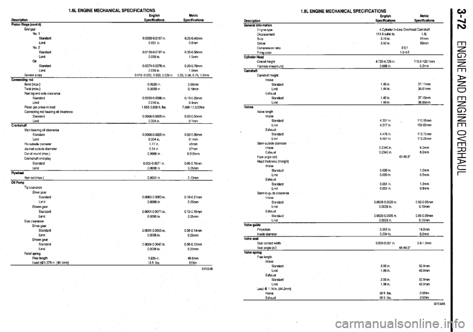
1.6L ENGINE MECHANICAL SPECIFICATIONS English Metric
OWCriptkUl SpeciflCatiOllS Specifications
Piston Rings (cont’d)
End 9ap
No 1
standard 0 0096-00157,“. 0 25-O 40mm
Limit 0 031 1” 0 6mm
No 2
Standard 0 0136-O 0197 1” 0 350 mm
Ltmlt 0 039 I”. 1 Omm
04
standard 0 0079-O 0276 I” 0 2Q.O 70mm
Limit 0 039 I” 1 Omm
SeNlce SlZeS 0 010,O 020.0 030.0 039 m 0 25.0 50,O 75, 1 Omm
Connecting rod
Bend (max) 0 0020 I”. 0 05mm
Test (max.) 0 0039 I” 0 1Omm
Rod big end side clearance
Standard 0 0039-o 0096 I” 0.10-O 25mm
Limit 0 016 I” 0 4mm
Piston pm press-m load 1.6533,658 fl Ibs 7.500.17.500Nm
Connecbng red bearing al clealilnce
Standard 0 oowo 002u I” 0 02-O 05mm
Llmlt oOO41n 0 lmm
Crankshaft
Mm bearing MI clearance
Standard 0 ooot-0 0020 I”. 0 02-O 05mm
Llmlt 0 004 I”. Oimm
Pm outslde diameter 177m 45mm
Journal out&e diameter 224111
57mm
Out-of-round (max )
00006lll 0 015mm
Crankshaft end.play
SIatU&rd 0 002-O 0071 1” 0 05-O 16mm
Llmlt 0 0096 I” 0 25mm
Flywheel
Run-out (max ) 0 0051 I” 0 13mm
011 Pump
lip clearance
Drive gear
Standard 0 0063.0 W63 m. 016.021mm
Llmlt
OCW6lfl 0 25mm
Driven gear
standard 0 0051-O 0071 I”. 0 136 16mm
Llmlt 0 0096 I”. 0 25mm
Side clearance
Dive gear
standard 0 0331.0 0055 I”. 0 060 14mm
Llmlt
00096lll 0 25mm
then gear
Standard 0 0024-O 0047 I” 006.0 12mm
Limit 0.0096 I” 0 25mm
R&l spring
Free length 1635 I” 46 6mm
Load (01 579 I” (40 tmm) 13 11 Ibs 61Nm
93153m Standard 146111 37 15mm
Llmlt 1441n 36 65mm
Limit
Exhaust
Intake
Standard
Llmtt 4 476 in
4 457 I”
0 2340 I”
0 2340 1”
45-45 5” 110.15mm
109.65mm
11370mm
11325mm
6 Omm
6 Omm
1 Omm
0 5mm
13mm
0 6mm
0 @JOB-0 0020 m 0 02-O 05mm
0 0039 I” 0 1Omm
Seat angle (all)
Valve spring
Free length
Intake
standard
Llmlt
EXhaUSt
standard
Llmlt
Load B 1 74 I” (44 2mm)
Intake
Exhaust 2 cm I”
1961n
2 w I”
1961n
59 It Ibs.
59 It lbs 44-44 5”
50 9mm
49.9mm
50 9mm
49.9mm
216Nm
216Nm
93153&!6
Page 135 of 408
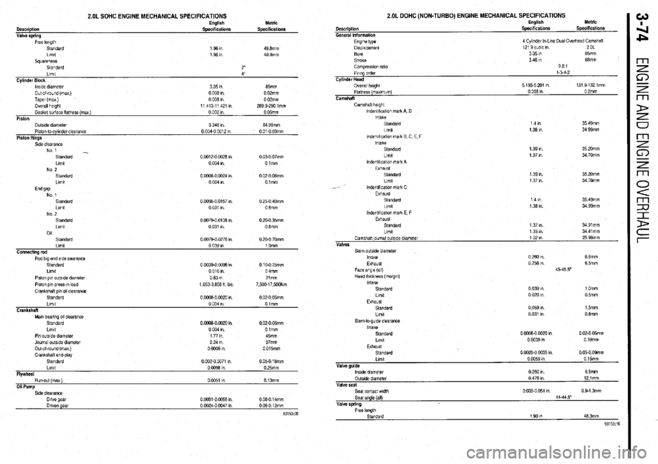
2.OL SOHC ENGINE MECHANICAL SPECIFICATIONS
Description
General Information
2.OL DOHC (NON-TURBO) ENGINE MECHANICAL SPECIFICATIONS English
Specifications Metric
Speciticatlonr Description
Valve sorino Engbsh
Specifications Metric
Specifications
Engine type
Dlsplacemenl
Bore
Stroke
Comprwon rat10
Flung order
Cylinder Head
Overall height
Flatness (maximum)
Camshaft 4 Cylmdet In-Lone Dual Overixad Camshaft
12’ 3 cubic m 2OL
3351n 85mm
3 46 I” 68mm
981
l-54-2
5 193.5 201 Ill 131 9.1321mm
0 008 1” 0 2mm S&dard
Llmlt
Squareness
Standard
Gasket surface flatness (mex Llmll
) Cylinder Block
Piston lnslde diameter
Outside dlameler O&of-round (max)
Piston-lo-cylinder clearance Taper (max)
Piston Rings Overall height 1 36 I”
1 96 I”
2”
0 002 I”. 4”
0 05mm 335m
3 346 I”. 65mm
64 99mm 0 008
0 I”.
004-o 04312 0 02mm
I” 0 008
0 I”
01-O 03mm 0 02mm
11 413.11 421 I” 263 Q-290 lmm m
Camshaft height
lndentlficaiw mark A, D
Intake
Standard
Llmlt
lndentll!cat!on mark B C, E, F
Intake
Standard
Llmlt
lndentlllcallon mark A
Exhaust
Standard
Lrmt
lndenbllcabon mah C
Exhaust
Standard
Limit 35 49mm
34 99mm 14m
1 36 I”.
0.0012-0 0026 I”.
0 004 I” 0 03-O 07mm
01mm 35 20mm
34 70mm 1 39 I”.
1 37 I”.
7 m 1 39 I”.
1 37 I”. 35 20mm
34 70mm 0 0008-O 0024 I”
0 004 I” 0 02-O 06mm
Olmm
14m
1 38 I”. 35 49mm
34 QQmm 0 0098-0 0157 I”.
0 031 I” 0 25.0 40mm
0 6mm
0.0079-O 0136 I”.
0 031 I” 0 20-O 35mm
08mm
0 0079-O 0276 I”.
Stem outside diameter
Intake
Exhaust
Face angle (all)
Head lhlckness (margm)
Intake
Standard
Llmlt 0 260 I”. 6 6mm
0 256 I”. 6 5mm
45-45 50
0 039 WI. 1 Omm
0 020 I”. 0 5mm Piston pm outside diameter
Piston p,” press-!” load
Crankshaft PI” 011 clearance
Standard 0631ll
1,653.3,656 ft Ibs 21mm
7,500.17,5WNm
0 oooa-o 0020 In. 0 02-O 05mm
Exhaust
Standard
Limit 0 059 I”.
0 031 I”. 15mm
0 6mm Limit
0 004 I” Olmm
Crankshaft
Man bearing 011 clearance
Standard
Llmlt
Pm outside dwneler
Journal outslde diameter
Out-of-round (max)
CrankshaH end-play
Standard
Limtt
Flywheel
Run-out (max)
Oil Pump 0 ciw0 0020 I”. 0 02-O 05mm
0 004 I”. Olmm
1771n 45mm
2 24 I” 57mm
0 0006 I” 0 015mm
0 002-O 0071 I” 0 05-O 16mm
0 0098 I” 0 25mm
0 0051 I” 0.13mm Stem-to-gude clearance
Intake
Standard
Llmlt 0 oooa-o 0020 I” 0 02-O 05mm
0 0039 in 0 1Omm
Exhaust
Standard 0 0020-O 0035 I” 0 05-O 09mm
Llmlt
Valve guide
lnstde diameter
OutsIde diameter
Valve seat
Seal contact wldlh
Seat angle (all)
Valve spring 0 W59 m 0 15mm
026Om 66mm
0 476 I” 121mm
0 035-o 051 I”. 0 Q-1 3mm
44-44.5
Page 136 of 408
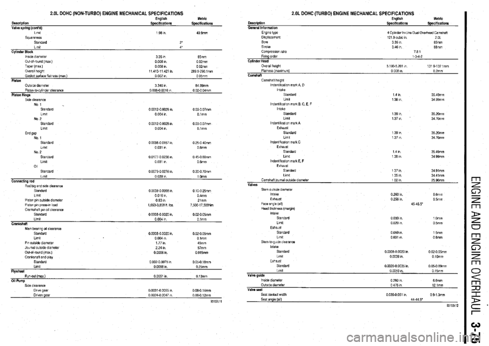
2.OL DOHC (NON-TURBO) ENGINE MECHANICAL SPECIFICATIONS
Cyltnder Block
lnslde dnnetet
335m 65mm
Out&round (ma)
0 006 I” 0 02mm
Taper (ma)
oooh
0 OPmm
Overall haght
11 413-l 1 421 I”. 269 9-290 lmm
Gasket surface flatness (ma )
0 002 I” 0 05mm
Piston
Side clearance
No 1
Standard
Llmlt
No 2
Standard
Llmlt 0 0012-O 0028 I”. 0 03-O 07mm
0 004 I” Olmm
0 0012-O W26 I”
0 03-O 07mm
0 004 I” Olmm
Standard
00096-0 0157 I” 0 25-O 40mm
Limit
0 031 I” 0 8mm
No 2
Standard
0 0177-O 0236 I” 0 45-O 6Omm
Llmlt 0 031 I”. 0 6mm
011
Standard
0 0079.0 0276 I” 0 20-O 70mm
Piston pin outslde diameter
Ot331n
Piston own oress-m load
1.653-3.856 n Ibs Zlmm
7 500-l 7 500Nm
Mm bearing 011 clearance
Standard
Llmlt
Pin outsIde diameter
Journal outslde diameter
Out-of-round (max )
Crankshall end&v 0 OOOB-0 0020 1” 0 02-O 05mm
0 004 I” Olmm
1 77 I”. 45mm
2 24 I”. 57mm
0 0006 I” 0 015mm
Standard’ ‘
0 002-O 0071 I” 0 05-O 16mm
Llmlt
0 0096 I”. 0 25mm
FlVWheel
Run-out (max)
0 BO51 I” 0 13mm
Oil Pump Description
General Information
2.OL DOHC (TURBO) ENGINE MECHANICAL SPECIFICATIONS English
Specifications Metric
Specifications
Camshafl height
lndentlkcatlon mark A. D
Intake
Standard
1 4 In 35 49mm
Llmlt
1 36 I” 34 99mm
lndentlflcatlon mark E C. E, F
Intake
Standard 1 39 I”. 35 20mm
Llmlt 1 37 I”. 34 70mm
lndentlflcal!on mark A
Exhaust
Standard
1 39 I”. 35 20mm
Llmlt
1 37 I”. 34 70mm
lndentlflcatlon mark C
Exhaust
Standard
1 4 I” 35 49mm
Llmlt
1 36 I” 34 99mm
lndentlflcatlon mark E, F
Exhaust
Standard
1 37 I”. 34 91mm
Llmlt
1351n 34 41 mm
Camshaft journal outslde dlametar
1021n
25 96mm
Vhf&S
Standard
LilTlIt
Exhaust 0 039 I”. 1 Omm
0 020 I”. 0 5mm
Standard
Llmlt
Stem-to-guide clearance
Intake
Standard
Llmtt
Exhaust
Standatd
Limit
Valve guide
lnslde diameter
OutsIde dlametat
Valve peat
Seat contact wdth
Seat angle (all) 0 059 I”. 15mm
0 031 I”. 0 6mm
0 0008-0 0020 I” 0 02-O 05mm
0 0039 I” OlOmm
0 0020-0 0035 I”. 0 05.0 09mm
0 0059 I”. 015mm
0260 In.
66mm
0 476 I” 12 lmm
0 035-o 051 m 0 9.1 3mm
44.44 5”
93153c12
Page 138 of 408
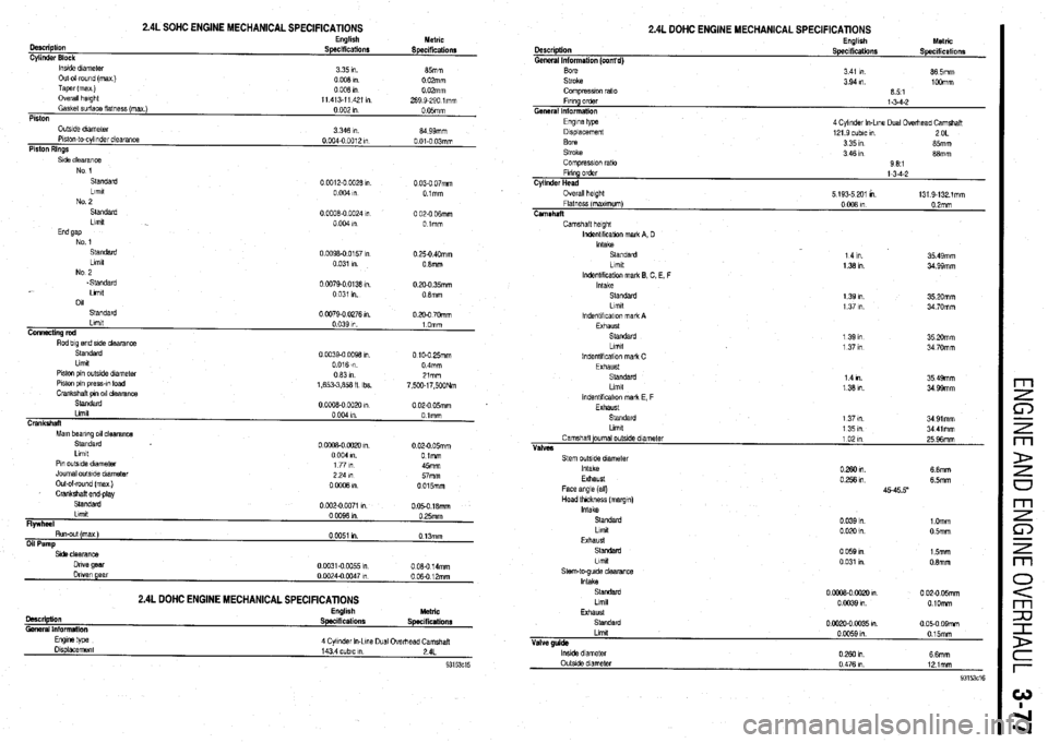
2.4L SOHC ENGINE MECHANICAL SPECIFICATIONS English
Description
Specifications
Cylinder Block
lnstde dnmeter
3 35 I”.
Out-o-round (max )
0008ln
Taper(max)
0008ln
Overall hwght
11 413-11 421 I”
Gasket &ace flatness (max )
0 002 I”
Piston Metric
Specifications
85mm
0 02mm
0 02mm
289 9-290 lmm
0 05mm
OutsIde dlameler
Plslon-to-cylinder clearance
Piston Rings 3 346 I” 04 99mm
0 004-o 0012 I” 0 01-O 03mm
Standard
0 0012-O 0928 I” 0 03-O 07mm
Lfmlt
0 004 I” Olmm
No 2
Standard 00008-O
0024 I” 0 02-O ffimm
Llmlt
0004," Olmm
End gap
No 1
Standard 0
0098-O 0157 In 0 25-O 40mm
Llmlt
0 031 I”. 0 Smm
No 2
.Standard
Llmlt
011
Standard 0 0079-o 0138 I”
0 031 I”.
00079-002761". 0 20-O 35mm
0 8mm
0 20-O 70mm
Standard
Llmlt
Piston pin outside dlametar
Piston pin press-m load
Crankshaft om 011 clearance 0 0039-o 0098 I” 0 10.0 25mm
0 016 m 0 4mm
0631n 21mm
1,653-3,&a fl Ibs.
7,500~17,500Nm
Standard
0 02-O 05mm
Mam beanna 011 clearance
Standard
0 OuoE-0 0020 I”. 0.024 05mm
Limit
0004 I”. 0 lmm
Pm outslde diameter
1 77 I” 45mm
Journal outside diameter 2P4m wmm
Out-al-round (max )
Crankshaft end-play
o-i& I”. _
0015mm
Flywheel Standard
Ltmit 0002-00071 I”.
0 050 18mm
000981n 0 25mm
Side clearance
Dnve gear
Driven gear
lMCriptlOfl
General Information OOm-00055,"
0 0024-O 0047 I”
2.4L DOHC ENGINE MECHANICAL SPECIFICATIONS English
Specifications 0 08.0 14mm
006012mm
Metric
Specifications
4 Cyi~nder In-Lme Dual Overhead Camshaft
143 4 cubtc I”. 24L
2.4L DOHC ENGINE MECHANICAL SPEClFlCATlONS
Description
General Information (cont’d) English
Specifications Metric
Specifications
Fmng order
Cylinder Head
Overall height
Flatness (maxtmum)
Camshaft l-3-4-2
5 193.5 201 K1 131 9-132 lmm
0 008 I” 0.2mm
Camshaft height
lndentlhcabon malk A, D
Intake
Standard
Limit
lndentlkcatlon mark 8, C, E. F 1 4 I”. 35 49mm
1331n 34 99mm
Head thickness (margtn)
Intake
StaMkrd
hrnft
Exhaust
Standard
Llmlt
Stem-to-gulda clearance
Intake
Standard
Llmlt
Exhaust
Standard
Limit
Valve guide
lnslde diameter
Outside diameter 0 039 I”. 1 Omm
0 020 I”. 05mm
0 059 I” 15mm
0 031 I” 0.8mm
0 cooa- NJ20 I”. 0 02-O 05mm
0 0039 I”. O.lOmm
0002+0M)35m 005.009mm
0 0059 I”. 015mm
02mm 6 6mm
0 476 I”. 121mm