1900 MITSUBISHI DIAMANTE oil level
[x] Cancel search: oil levelPage 36 of 408
_. .I ..-.
-._.
GENERALINFORMATIONAND MAINTENANCE l-37
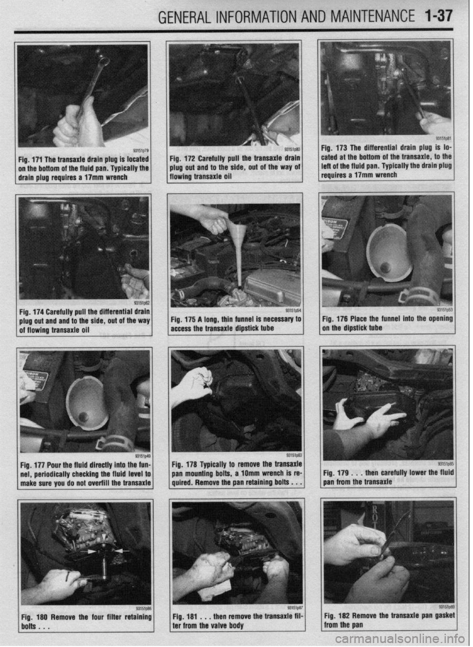
Fig. 172 Carefully pull the transaxie drain
plug out and to the side, out of the way oi
flowing transaxie oil Fig. 173 The differential drain plug is lo-
cated at the bottom of the transaxie, to the
left of the fluid pan. Typically the drain plug
reauires a 17mm wrench
periodically checking the fluid level to
make sure you do not overfill the transaxle pan mounting
bolts, a 1Omm wrench is re-
Fig. 179 . . , then carefully lower the fluid
quired. Remove the pan retaining bolts . . . pan from the transaxle
Fig, 181 . , . then remove the transaxie film
ter from the valve body Fig. 182 Remove the transaxie pan
gasket from the pan
Page 37 of 408
t
1-38 GENERALINFORMATIONAND MAINTENANCE
11 I Add the recommended automatic transaxle
fluid to the transaxle through the dipstick tube. You
will need a long necked funnel, or a funnel and tube
to do this. A quick check of the capacities chart later
in this Section will reveal the capacity of the transaxle
in your vehicle. On a first fill after removing the pan
and filter, this number should be cut into a ‘hand
checked on the dipstick before refilling.
12. With the transaxle in P, put on the parking
brake, block the front wheels, start the engine and let
it idle. DO NOT RACE THE ENGINE. DO NOT MOVE
THE LEVER THROUGH ITS RANGES.
13. With the lever in Park, check the fluid level. If
it’s OK, take the car out for a short drive, park on a
level surface, and check the level again, as outlined
earlier in this section. Add more fluid if necessary. Be
careful not to overfill, which will cause foaming and
w fluid loss. n of the transfer case filler
3. Remove the filler and the drain plug and allow
the oil to drain into the drain pan.
4. After the fluid has drained completely, install
the drain plug and tighten to 24 ft. Ibs. (32 Nm).
5. Refill the transfer case to the proper level with
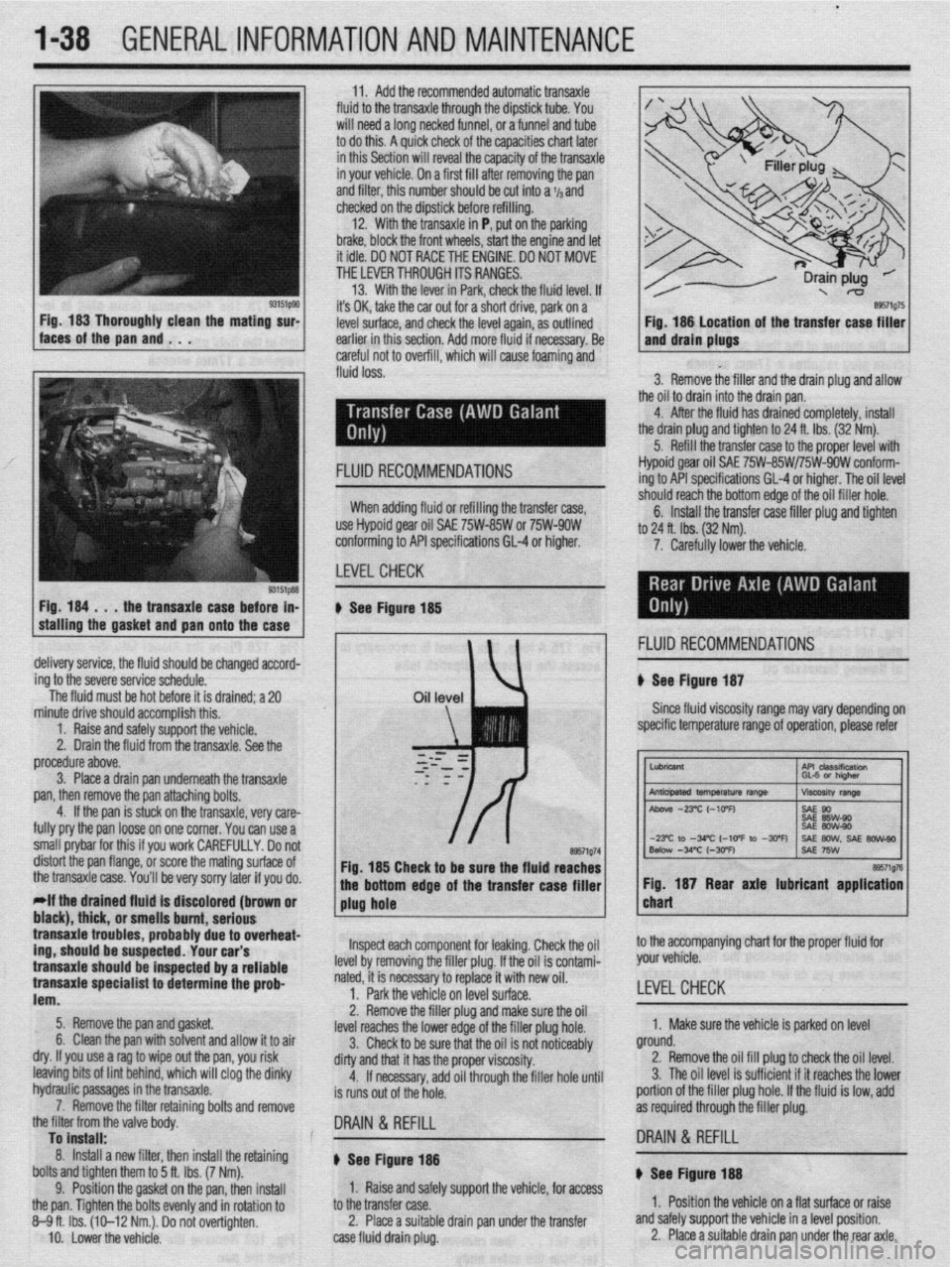
Fig. 184 . . .
the transaxle case before in-
stalling the gasket
and pan onto the case FLUID RECOMMENDATIONS Hypoid gear oil SAE 75W-85W/75W-9OW conform-
ing to API specifications GL-4 or higher. The oil level
-‘-,*I’ -nnnh +‘* “%om edge of the oil filler hole.
nxfer raw filler nlm and tinhtm When adding fluid or refilling the transfer case,
use Hypoid gear oil SAE 75W-85W or 75W-9OW
conforming to API specifications 61-4 or higher.
LEVELCHECK 6. Install the tra .._._. ____ .._. T.-J _.._ .lJ . .._..
to 24 ft. lbs. (32 Nm).
7. Carefully lower the vehicle.
u See Figure 185
, 1 FLUID RECOMMENDATIONS
delivery service, the fluid should be changed accord-
ing to the severe service schedule.
The fluid must be hot before it is drained; a 20 u See Figure 187
Since fluid viscosity range may
vary depending on
specific temperature range of operation, please refer
~~
tne transaxle case.
You’ll be very sorry later if you do. bottom edge of the transfer case filler 1 1 Fig. 187 Rear axle lubricant application I
*If the drained fluld is discolored (brown or
1 plug hole chart black), thick, or pmmll~ hmmt nnrinmm I transaxle trouble .llln3llU ““III., url,““P s, probably due to overheat-
,r..rr,rA “#.a.- rrdr
trig, should be susp~~lr;u. lvUl vLlr J
transaxle should be inspected by a reliable
transaxle specialist to determine the prob-
lem.
5. Remove the pan and gasket.
6. Clean the pan with solvent and allow it to air
dry. If you use a rag to wipe out the pan, you risk
leaving bits of lint behind, which will clog the dinky
hydraulic passages in the bansaxle.
7. Remove the filter retaining bolts and remove
the filter from the valve bodv. lnsoect each component for leaking. Check the oil
he filler plug. If the oil is contami-
ry to replace it with new oil.
if% nn IPVPI z11rf2r~
level by removing t
nated, it is necessa
1. Park the vehi,., -.. ,-.“, __. ,“-_.
2. Remove the filler plug and make sure the oil
level reaches the lower edge of the filler plug hole.
3. Check to be sure that the oil is not noticeably
dirty and that it has the proper viscosity.
4. If necessary, add oil through the filler hole until
is runs out of the hole. to the accompanying chart for the proper fluid for
your vehicle.
LEVEL CHECK
1. Make sure the vehicle is parked on level
ground.
2. Remove the oil fill plug to check the oil level.
3. The oil level is sufficient if it reaches the lower
portion of the filler plug hole. If the fluid is low, add
as required through the filler plug.
To install: .
8. Install a new filter, then install the retaining
bolts and tighten them to 5 ft. Ibs. (7 Nm).
9. Position the gasket on the pan, then install
the pan. Tighten the bolts evenly and in rotation to
8-9ft. Ibs. (10-12 Nm.). Do not overtighten.
IO. Lower the vehicle. DRAIN & REFILL
I8 DRAIN & REFILL
u See Figure 188 ) See Figure- 14
1. Raise and safely support the vehicle, for access
to the transfer case.
2. Place a suitable drain pan under the transfer
case fluid drain plug. 1. Position the vehicle on a flat surface or raise
and safely support the vehicle in a level position.
2. Place a suitable drain pan under the rear axle.
Page 38 of 408
GENERALINFORMATIONAND MAINTENANCE 1-39
leak. In most cases, you will be able to trace the leak
to a loose fitting or damaged hose.
Evaporating ethylene glycol antifreeze will have a
sweet smell and leave small, white (salt-like) de-
oosits, which can be heloful in tracino a leak. glove box and passenger side floorboard area, and
check the carpet for any signs of moisture. The
smartest way to go about finding a leak visually is to
first inspect any and all joints in the system such as
where the radiator hoses connect to the radiator and
the engine. Another thing to look for is white crusty
stains that are signs of a leak where the coolant has
6. Install the filler plug and tighten to’24 ft. Ibs.
(32 Nm).
7. If raised, carefully lower the vehicle. amount of fluid. The level should ieach thk bottom of me rating on It, lap3 1s a danciara 10 use out some
the oil filler hole. A Qss
tin,t.as ran +tw,, 4liE cars are higher. Overpressurizing the system can
lose, or worse, in the radiator or
your cooling system is con- IIC~KI LUG MU PuaJbly cause an injury or a burn if
s of a leak are probable. There the coolant is hot. Overpressurizing is normally con-
WI” U”.VlUl ,.“,,I I” 9” about finding the source of trolled by the radiator cap which has a vent valve in it
your leak. which is opened when the system reaches it’s maxi-
The first wav should be a visual insnection. Durina mum pressure rating. To pressure test the system: 7 “1sl I ly”lsJa IJ” Wll” IJU
If a the fluid level of
stantly low, the chance cause a rupture in a I:
h.n+n. nrrrn nnA . . . . ..I.
FLUID RECOMMENDATIONS the visual inspection, look around the &tire engine -
area including the radiator and the heater hoses. The *The pressure test should be performed with
the enaine OFF.
A good quality ethylene glycol based or other alu-
minum compatible antifreeze is recommended for
use in the vehicles covered by this manual. It is best
to add a 50150 mix of antifreeze and distilled water to
avoid diluting the coolant in the system. interior of the car should be inspected behind the
LEVELCHECK
recovery tank and its marking as a guideline.
*Never overfill the recovery tank.
A coolant level that consistently drops is usually a
sign of a small, hard to detect leak, although in the
worst case it could be a sign of an internal engine “_y “,~--
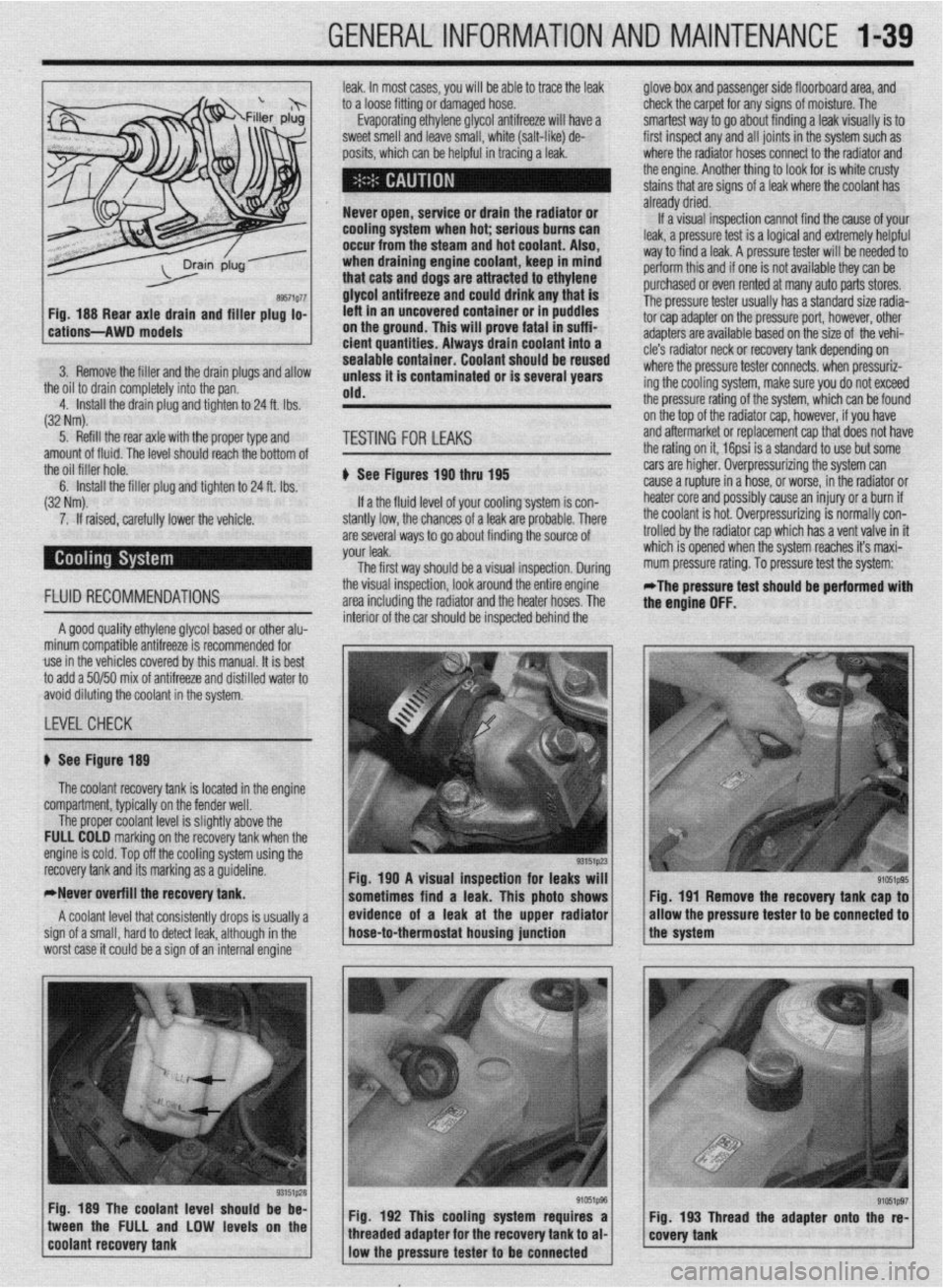
1 Fia. 190 A visual insaection for leaks will 1
sometimes find a leak. This photo shows Fig. 191 Remove the recovery tank cap to
/ * ,, / evfdence of a leak at the upper radfator
* / /the system allow the pressure tester
to be connected to hose-to-thermostat housing junction
Fig. 189 The coolant level should be be-
1 coo,ant recovery tank tween the FULL and LOW levels on the
“‘~‘_I j Fig. 192 This cooling system requires a Fig. 193 Thread the adapter onto the re-
e’ffi1pg7 / g’051p96 / 1 covety tank threaded adapter for the recovery tank to al-
low the pressure tester to
be connected
Page 40 of 408
.
GENERALINFORMATIONAND MAINTENANCE l-41
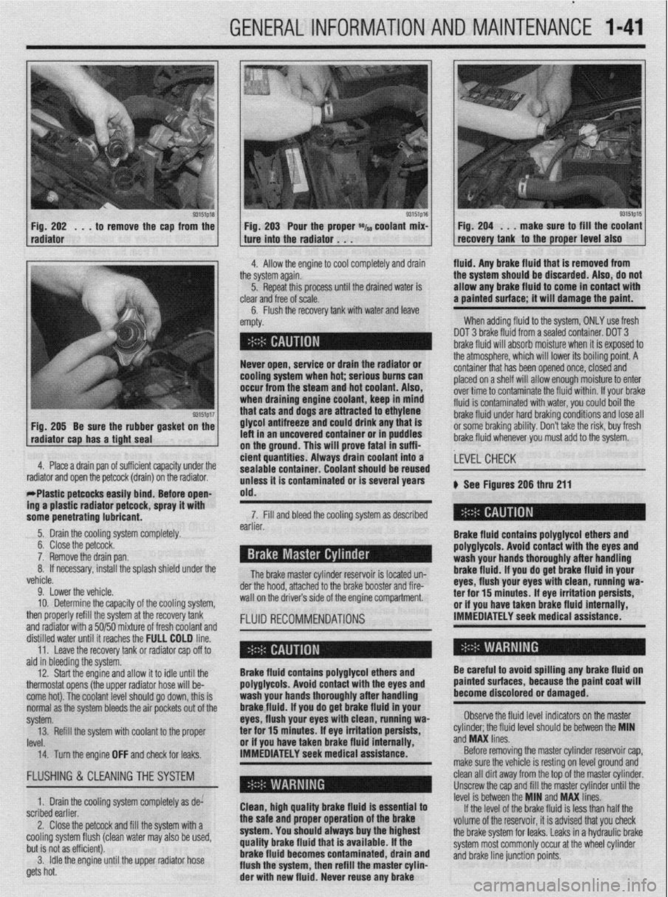
93151p18 Fig. 202 . , . to remove the cap from the
radiator
93151p17 Fig. 205 Be sure the rubber gasket on the
radiator cap has a tight seal e Fig. 203 Pour the proper *I~ coolant mix- 1 Fig. 204 . . . make sure to fill the coolant
recovery tank to the proper level also ture into the radiator . . .
.I
4. Allow the engine to cool completely and drain fluid. Any brake fluid that is removed from
ie system again.
5. Repeat this processuntil the drained water is
lear
and free of scale.
6. Flush the recovery tank with water and leave ’
mpty. the system should be discarded. Also, do not
allow any brake fluid to come in contact with
a painted surface; it will damage the paint.
When adding fluid to the system, ONLY use fresh
DOT 3 brake fluid from a sealed container. DOT 3
brake fluid will absorb moisture when it is exposed to
.a . . . , .*a. . . * .*. . .
- Never open, service or drain the radiator or
cooling system when hot; serious bums can
occur from the steam and hot coolant. Also,
when draining engine coolant, keep In mind
that cats and dogs are attracted to ethylene
glycol antifreeze and could drink any that is
left in an uncovered container or in puddles
on the ground. This will prove fatal in suffi-
4. Place a drain pan of suff i ’ 1 . . . ..I .I. 1,~ cient quantities. Always tne atmospnere, wnrcn wnr rower 1r.s oourng pomr. A
container that has been opened once, closed and
placed on a shelf will allow enough moisture to enter
over time to contaminate the fluid within. If your brake
fluid is contaminated with water, you could boil the
brake fluid under hard braking conditions and lose all
or some braking ability. Don’t take the risk, buy fresh
brake fluid whenever you must add to the system.
crenr capacrry unaer me
drain) on the radiator.
rrrasuc perwcss easuy bind; Before open-
ing a plastic radiator petcock, spray it with
some penetrating lubricant. drain coolant into a
earner. sealable container. Coolant should be reused
unless it is contaminated or is several years
old.
The brake master cylinder ~a~~~~r,~~ :A I~nnL.4 n-n 7. Fill and bleed the cooling system as described
Brake fluid contains polyglycol ethers and
polyglycols. Avoid contact with the eyes and ,LEVEL CHECK
wash your hands thoroughly after handling
brake fluid. If vou do oet brake fluid in vour
eyes, flush your eyeswith clean, runniug wa-
a-.. ‘Y-- ar -l-..n-- II -.._ I____ k See Figures 206 thru 211
.a-11-- - __-PA._ radiator and open the petcock (
- w&1--x3_ --mm.._..- . . ..-I...
5. Drain the cooling system completely.
6. Close the petcock.
7. Remove the drain pan.
If necessary, install the splash shield under the 8.
L.-l
venicie.
9. Lower the vehicle.
10. Determine the capacity of the cooling system,
then properly refill the system at the recovery tank
and radiator with a 50/50 mixture of fresh coolant and
fKm”“ll 15 IUMLC” “II- brake booster and fire- der the hood, attached to the
wall on the drivers side of the engine compartment.
FLUID RECOMMENDATIONS rer mr 13 mmures. IT eye irriIauon persim, or if you have taken brake fluid internally,
IMMEDIATELY seek medical assistance.
ala in oreerring me sysrem.
12. Start the engine and allow it to idle until the
thermostat opens (the upper radiator hose will be-
come hot). The coolant level should go down, this is
normal as the system bleeds the air pockets out of the
svstem.
IRVf!l ._._. 14. Turn the engine OFF and check for leaks. IMMEDIATELY seek medical assistance.” Brake fluid contains polyglycol ethers and
polyglycols. Avoid contact with the eyes and
wash your hands thoroughly after handling
brakefluid. If you do get brake fluid in your
eyes, flush your eyes with clean, running wa-
or if vou have taken brake fluid internallv.
Before removing the master cylinder reservoir cap,
make sure the vehicle is resting on level ground and Be careful to avoid spilling any brake fluid on
painted surfaces, because the paint coat will
become discolored or damaged.
Observe the fluid level indicators on the master
._ ._ __
‘eve1 should be between the MIN
ano
ivw unes. 13. Refill the system with coolant to the proper ter for 15 minutes; If eye irritation persists, cylinder; the tluld II
..J ..I” I....
FLUSHING & CLEANINGTHE SYSTEM
1. Drain the cooling system completely as de:
scribed earlier.
2. Close the petcock and fill the system with a
cooling system flush (clean water may also be used,
but is not as efficient).
3. Idle the engine until the upper radiator hose
gets hot. Clean, high quality brake fluid is essential to
the safe and proper operation of the brake
system. You should always buy the highest
quality brake fluid that is available. If the
brake fluid becomes contaminated, drain and
flush the system, then refill the master cylin-
der with new fluid. Never reuse any brake clean all dirt away from the top of the master cylinder.
Unscrew the cap and fill the master cylinder until the
level is between the MIN and MAX lines.
If the level of the brake fluid is less than half the
volume of the reservoir, it is advised that you check
the brake system for leaks. Leaks in a hydraulic brake
system most commonly occur at the wheel cylinder
and brake line junction points.
Page 41 of 408
1-42 GENERAL~INFORMATION AND MAINTENANCE
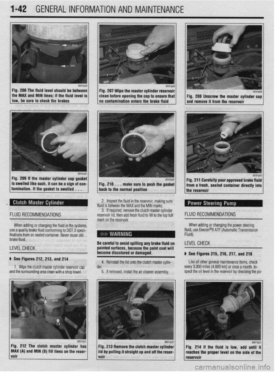
Fig. 206 The fluid level should be between
llow,be*“retoch~ckiebrake~ . the MAX and MIN hnes if the fhud level IS
93151p31 Fig. 209 If the master cylinder capgasket
is swelled like such, it can be a sign of con-
tamination. If the gasket is swelled . . . Fig. 207 Wipe the master cylinder reservoir
clean before opening the cap to ensure that
no contamination enters the brake fluid
Fig. 210 . . .
make sure to push the gasket
back to the normal position
93151p29 I Fig. 208 Unscrew the master cylinder cap
and remove it from the reservoir
Fig. 211 Carefully pour approved brake fluid
from a fresh, sealed container directly into
the reservoir
2. Inspect the fluid in the reservoir, making sure
fluid is between the MAX and the MIN marks.
FLUID RECOMMENDATIONS
When adding or changing the fluid in the systems,
use a quality brake fluid conforming to DOT 3 speci-
fications from an sealed container. Never reuse old
brake fluid.
LEVEL CHECK
b See Figures 212, 213, and 214
1. Wipe the clutch master cylinder reservoir cap
and the surrounding area clean with a shop towel. 3. If required, remove the clut ch master cylinder
reservoir lid. then add fresh fluid I FLUID RECOMMENDATIONS
mark on the’reservoir. to fill to the top full
When adding or changing the power steering
fll$,“” Dexron@il ATF (Automatic Transmission
-
- .
Be careful to avoid sf Billing any brake fluid on LEVELCHECK
painted surfaces, bet
:ause the paint coat will
become discolored or damaged.
b See Figures 215, 216, 217, and 218
4. Reinstall the lid onto the clutch master cylin- Like all other general maintenance items, check
der. every 3,OOfl miles (4,800 km) or once a month. In-
5. If removed, install the air cleaner assembly. spect the oil level in the reservoir by checking the po-
Fig. 212 The clutch master cylinder has
MAX (A) and MIN (B) fill lines on the reser
volr
Page 42 of 408
GENERALINFORMATIONAND MAINTENANCE l-43
l Special car washing detergent is the best to
use. Liquid dishwashing detergent can remove wax
and leave the car’s paint unprotected and in addition
some liquid detergents contains abrasives which can
scratch the paint.
l Bird droppings should be removed from the
paintwork as soon as possible, otherwise the finish
may be permanently stained.
When the car is driven immediately after be-
ing washed, apply the brakes several times
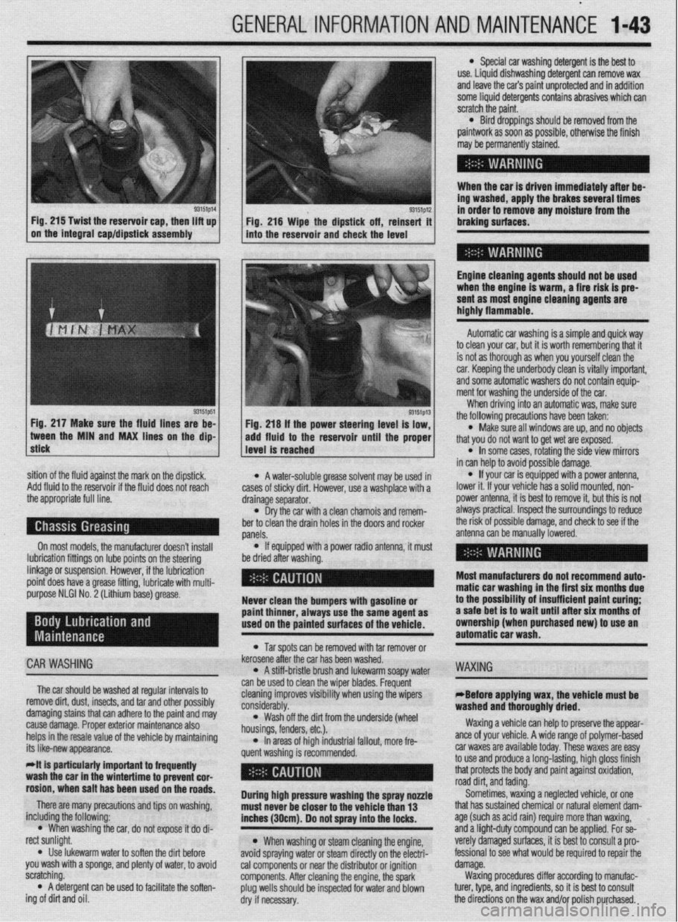
93151p14 93151p12 Fig. 215 Twist the reservoir cap, then lift up
I I
in order to remove any moisture from the
Fig. 216 Wipe the dipstick off, reinsert it braking surfaces.
on the integral cap/dipstick assembly
into the reservoir and check the level
I
Engine cleaning agents should not be used
when the engine is warm, a fire risk is pre-
sent as most engine cleaning agents are
highly flammable.
sition of the fluid against the mark on the dipstick,
Add fluid to the reservoir if the fluid does not reach
the appropriate full line.
On most models, the manufacturer doesn’t install
lubrication fittings on lube points on the steering
linkage or suspension. However, if the lubrication
point does have a grease fitting, lubricate with multi-
purpose NLGI No. 2 (Lithium base) grease.
CAR WASHING
The car should be washed at regular intervals to
remove dirt, dust, insects, and tar and other possibly
damaging stains that can adhere to the paint and may
cause damage. Proper exterior maintenance also
helps in the resale value of the vehicle by maintaining
its like-new appearance.
Mt is particularly important ta frequentiy
wash the car in the wintertime to prevent cor-
rosion, when salt has been used on the roads.
There are many precautions and tips on washing,
including the following:
l When washing the car, do not expose it do di-
rect sunlight.
. Use lukewarm water to soften the dirt before
you wash with a sponge, and plenty of water, to avoid
scratching.
l A detergent can be used to facilitate the soften-
ing of dirt and oil. * A water-soluble grease solvent may be used in
cases of sticky dirt. However, use a washplace with a
drainage separator.
l Dry the car with a clean chamois and remem-
ber to clean the drain holes in the doors and rocker
panels.
l If equipped with a power radio antenna, it must
be dried after washing.
Never clean the bumpers with gasoline or
paint thinner, always use the same agent as
used on the painted surfaces of the vehicle.
l Tar spots can be removed with tar remover or
kerosene after the car has been washed.
l A stiff-bristle brush and lukewarm soapy water
can be used to clean the wiper blades. Frequent
cleaning improves visibility when using the wipers
considerably.
l Wash off the did from the underside (wheel
housings, fenders, etc.).
l In areas of high industrial fallout, more fre-
quent washing is recommended.
During high pressure washing the spray nonle
must never be closer to the vehicle than 13
inches (30cm). Do not spray into the locks.
l When washing or steam cleaning the engine,
avoid spraying water or steam directly on the electri-
cal components or near the distributor or ignition
components. After cleaning the engine, the spark
plug wells should be inspected for water and blown
dry if necessary. Automatic car washing is a simple and quick way
to clean your car, but it is worth remembering that it
is not as thorough as when you yourself clean the
car. Keeping the underbody clean is vitally important,
and some automatic washers do not contain equip-
ment for washing the underside of the car.
When driving into an automatic was, make sure
the following precautions have been taken:
l Make sure all windows are up, and no objects
that you do not want to get wet are exposed.
l In some cases, rotating the side view mirrors
in can help to avoid possible damage.
l If your car is equipped with a power antenna,
lower it. If your vehicle has a solid mounted, non-
power antenna, it is best to remove it, but this is not
always practical. Inspect the surroundings to reduce
the risk of possible damage, and check to see if the
antenna can be manually lowered.
Most manufacturers do not recommend auto-
matic car washing in the first six months due
to the possibility of insufficient paint curing;
a safe bet is to wait until after six months of
ownership (when purchased new) to use an
automatic car wash.
WAXING
eBefore applying wax, the vehicle must be
washed and thoroughly dried.
Waxing a vehicle can help to preserve the appear-
ante of your vehicle. A wide range of polymer-based
car waxes are available today. These waxes are easy
to use and produce a long-lasting, high gloss finish
that protects the body and paint against oxidation,
road dirt, and fading.
Sometimes, waxing a neglected vehicle, or one
that has sustained chemical or natural element dam-
age (such as acid rain) require more than waxing,
and a light-duty compound can be applied. For se-
verely damaged surfaces, it is best to consult a pro-
fessional to see what would be required to repair the
damage.
Waxing procedures differ according to manufac-
turer, type, and ingredients, so it is best to consult
the directions on the wax and/or polish purchased.
Page 55 of 408
.
2-8 ENGINEELECTRICAL
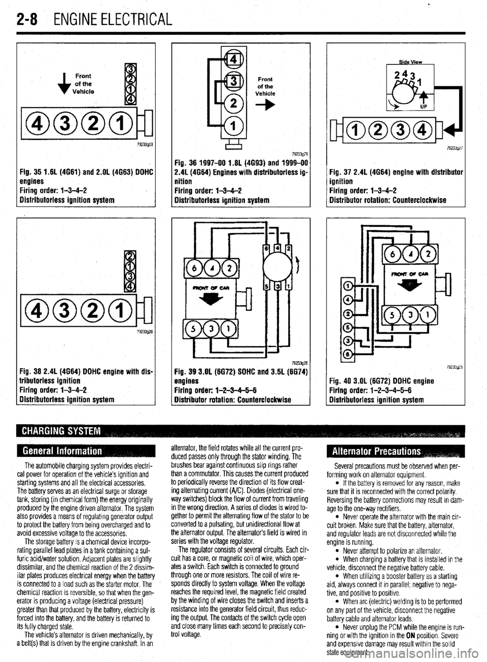
Front
of the
Vehicle
Fig. 35 1.61(4661) and 2.OL (4663) DDHC
engines
Firing order: l-3-4-2
Distributorless ignition system
Fig. 36 2.4L (4664) DDHC engine with dis-
lributorless ignition
Firing order: l-3-4-2
gistributorless ignition system
Front
of the
Vehicle
+
Fig. 36 1997-00 1.6L (4693) and 1999-00
2.41(4664) Engines with distributorless ig-
nition
Firing order: l-3-4-2
Distributorless ignition system
792!33g26 Fig. 39 3.OL (6672) SDHC and 3.5L (6674)
engines
Firing order: l-2-3-65-6
Distributor rotation: Counterclockwise Fig. 37 2.4L (4664) engine with distributor
ignition
Firing order: l-3-4-2
Distributor rotation: Counterclockwise
:ig. 40 3.OL (6672) DDHC engine
Yring order: l-2-3-4-5-6
Iistributorless ignition system
The automobile charging system provides electri-
cal power for operation of the vehicle’s ignition and
starting systems and all the electrical accessories.
The battery serves as an electrical surge or storage
tank, storing (in chemical form) the energy originally
produced by the engine driven alternator. The system
also provides a means of regulating generator output
to protect the battery from being overcharged and to
avoid excessive voltage to the accessories.
The storage battery IS a chemical device incorpo-
rating parallel lead plates in a tank containing a sul-
furic acid/water solution. Adjacent plates are slightly
dissimilar, and the chemical reaction of the 2 dissim-
ilar plates produces electrical energy when the battery
is connected to a load such as the starter motor. The
chemical reaction is reversible, so that when the gen-
erator IS producing a voltage (electrical pressure)
greater than that produced by the battery, electricity is
forced into the battery, and the battery is returned to
its fully charged state.
The vehicle’s alternator is driven mechanically, by
a belt(s) that is driven by the engine crankshaft. In an alternator, the field rotates while all the current pro-
duced passes only through the stator winding. The
brushes bear against continuous slip rings rather
than a commutator. This causes the current produced
to periodically reverse the direction of its flow creat-
ing alternating current (A/C). Diodes (electrical one-
way switches) block the flow of current from traveling
in the wrong direction. A series of diodes is wired to-
gether to permit the alternating flow of the stator to be
converted to a pulsating, but unidirectional flow at
the alternator output, The alternators field is wired in
series with the voltage regulator.
The regulator consists of several circuits. Each cir-
cuit has a core, or magnetic coil of wire, which oper-
ates a switch. Each switch is connected to ground
through one or more resistors. The coil of wire re-
sponds directly to system voltage. When the voltage
reaches the required level, the magnetic field created
by the winding of wire closes the switch and inserts a
resistance into the generator field circuit, thus reduc-
ing the output. The contacts of the switch cycle open
and close many times each second to precisely con-
trol voltage. Several precautions must be observed when per-
forming work on alternator equipment.
l If the battery is removed for any reason, make
sure that it is reconnected with the correct polarity.
Reversing the battery connections may result In dam-
age to the one-way rectifiers.
l Never operate the alternator with the main cir-
cuit broken. Make sure that the battery, alternator,
and regulator leads are not disconnected while the
engine is running.
l Never attempt to polarize an alternator. l When charging a battery that is installed in the
vehicle, disconnect the negative battery cable.
l When utilizing a booster battery as a starting
aid, always connect it in parallel; negatrve to nega-
tive, and positive to positrve.
l When arc (electric) welding is to be performed
on any part of the vehicle, disconnect the negative
battery cable and alternator leads.
l Never unplug the PCM while the engine is run-
ning or with the ignition in the ON position. Severe
and expensive damage may result within the solid
state equipment.
Page 58 of 408
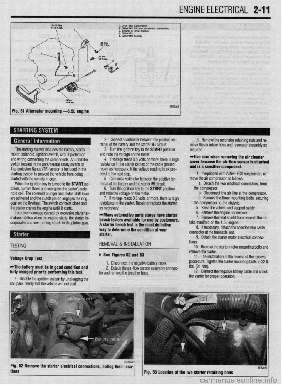
ENGINE ELECTRICAL 2-11
l.unVeMlil(GSflWtWJ
2.Gwwator harness con- connectk,,,
3. Engme OS, level d,pst,&
4 Generator
Fig. 51 Alternator mounting -3.51 engine
The starting system includes the battery, starter
motor, solenoid, ignition switch, circuit protection
and wiring connecting the components. An inhibitor
switch located in the park/neutral safety switch or
Transmission Range (TR) sensor is included in the
starting system to prevent the vehicle from being
started with the vehicle in gear.
When the ignition key is turned to the START po-
sition, current flows and energizes the starters sole-
noid coil. The solenoid plunger and clutch shift lever
are activated and the clutch pinion engages the ring
gear on the flywheel. The switch contacts close and
the starter cranks the engine until it starts.
To prevent damage caused by excessive starter ar-
mature rotation when the engine starts, the starter in-
corporates an over-running clutch in the pinion gear. 2. Connect a voltmeter between the positive ter-
minal of the battery and the starter B+ circuit.
3. Turn the ignition key to the START position
and note the voltage on the meter.
4. If voltage reads 0.5 volts or more, there is high
resistance in the starter cables or the cable ground,
repair as necessary. If the voltage reading is ok pro-
teed to the next step.
5. Connect a voltmeter between the positive ter-
minal of the battery and the starter M circuit,
6. Turn the ignition key to the START position
and note the voltage on the meter.
7. If voltage reads 0.5 volts or more, there is high
resistance in the starter. Repair or replace the starter
as necessary.
*Many automotive parts stores have starter
bench testers available for use by customers.
A starter bench test is the most definitive
way to determine the condition of your
starter. 3. Remove the resonator retaining nuts and re-
move the air intake hose and resonator assembly as
required.
rllse care when removing the air cleaner
cover because the air-flow sensor is attached
and is a sensitive component.
4. If equipped with Active-ECS suspension, re-
move the air compressor as follows:
a. Detach the two electrical connectors, from
the compressor.
b. Disconnect the air line at the compressor.
c. Remove the three mounting bolts, securing
the compressor to the chassis.
5. Raise the vehicle and support safely.
6. Remove the engine undercover.
7. Remove the heat shield from beneath the in-
take manifold on the 1.5L engine.
8. If necessary, detach the speedometer cable
connector at the transaxle end.
9. Detach the starter motor electrical connac-
TESTING
Voltage Drop Test
*The battery must be in good condition and
fully charged prior to performing this test. REMOVAL&INSTALLATION
# See Figures 52 and 53
1. Disconnect the negative battery cable.
2. Detach the air-flow sensor assembly connec-
tor and remove the breather hose.
1. Disable the ignition system by unplugging the
coil pack. Verify that the vehicle will not start. tions.
10. Remove the starter motor mounting bolts and
remove the starter.
11. The installation is the reverse of the removal
procedure. Tighten the starter mounting bolts to 22 ft.
Ibs. (31 Nm).
12. Connect the negative battery cable and check
the starter for proper operation.
9315zp19 Fig. 53 Location of the two starter retaining bolts