1900 MITSUBISHI DIAMANTE bolt pattern
[x] Cancel search: bolt patternPage 78 of 408
ENGlNEANDENGlNEOVERHAiJL 3-17
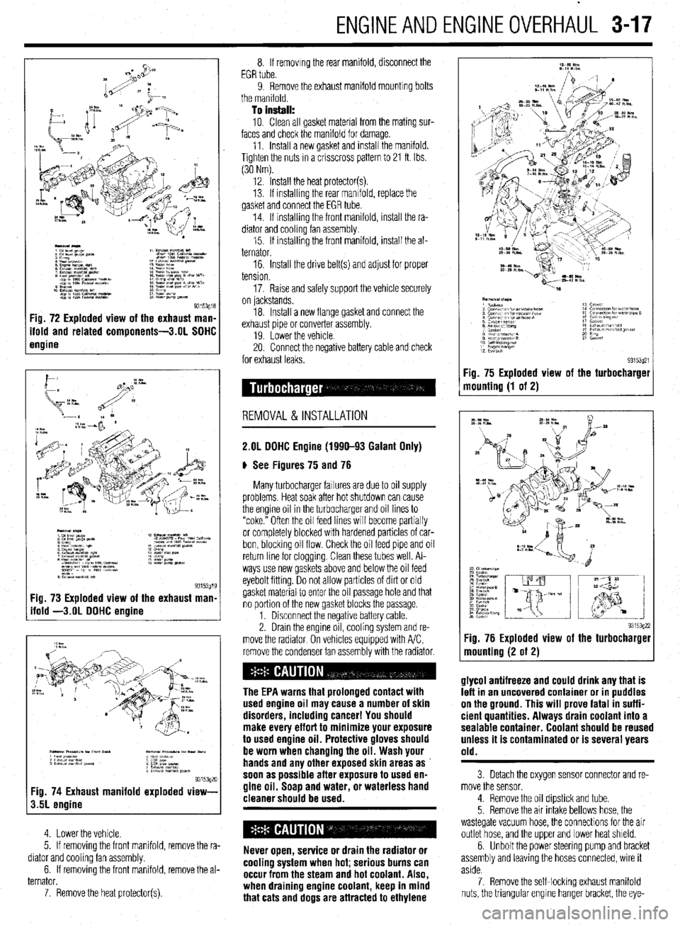
Fig. 73 Exploded view of the exhaust man
ifold -3.OL DOHC engine
9315392c Fig. 74 Exhaust manifold exploded view-
3.5L engine
4. Lower the vehicle.
5. If removing the front manifold, remove the ra-
diator and cooling fan assembly.
6. If removing the front manifold, remove the al-
ternator.
7. Remove the heat protector(s). 8. If removing the rear manifold, disconnect the
EGR tube.
9. Remove the exhaust manifold mounting bolts
the manifold.
To install:
10. Clean all gasket material from the mating sur-
faces and check the manifold for damage.
11. Install a new gasket and install the manifold.
Tighten the nuts in a crisscross pattern to 21 ft. Ibs.
(30 Nm).
12. Install the heat protector(s).
13. If installrng the rear manifold, replace the
gasket and connect the EGR tube.
14. If installing the front manifold, install the ra-
diator and cooling fan assembly.
15. If installing the front manifold, install the al-
ternator.
16. Install the drive belt(s) and adjust for proper
tension.
17. Raise and safely support the vehicle securely
on lackstands.
18. Install a new flange gasket and connect the
exhaust pipe or converter assembly.
19 Lower the vehicle
20. Connect the negative battery cable and check
for exhaust leaks.
REMOVAL&INSTALLATION
2.OL DOHC Engine (1990-93 Galant Only)
# See Figures 75 and 76
Many turbocharger failures are due to oil supply
problems. Heat soak after hot shutdown can cause
the engine oil in the turbocharger and oil lines to
“coke.” Often the oil feed lines will become partially
or completely blocked with hardened particles of car-
bon, blocking oil flow. Check the oil feed pipe and oil
return line for cloggrng. Clean these tubes well. Al-
ways use new gaskets above and below the oil feed
eyebolt fitting. Do not allow particles of dirt or old
gasket material to enter the oil passage hole and that
no portion of the new gasket blocks the passage.
1. Disconnect the negative battery cable.
2. Drain the engine oil, cooling system and re-
move the radiator On vehicles equipped with A/C,
remove the condenser fan assembly with the radiator.
The EPA warns that prolonged contact with
used engine oil may cause a number of skin
disorders, including cancer! You should
make every effort to minimize your exposure
to used engine oil. Protective gloves should
be worn when changing the oil. Wash your
hands and any other exposed skin areas as
soon as possible after exposure to used en-
gine oil. Soap and water, or waterless hand
cleaner should be used.
Never open, service or drain the radiator or
cooling system when hot; serious burns can
occur from the steam and hot coolant. Also,
when draining engine coolant, keep in mind
that cats and dogs are attracted to ethylene Fig. 75 Exploded view
mounting (1 of 2)
93153q21 the turbocharget
9315392: :ig. 76 Exploded view of the turbocharger
nounting (2 of 2)
glycol antifreeze and could drink any that is
left in an uncovered container or in puddles
on the ground. This will prove fatal in suffi-
cient quantities. Always drain coolant into a
sealable container. Coolant should be reused
unless it is contaminated or is several years
old.
3 Detach the oxygen sensor connector and re-
move the sensor.
4. Remove the oil dipstick and tube.
5. Remove the air intake bellows hose, the
wastegate vacuum hose, the connections for the air
outlet hose, and the upper and lower heat shield.
6. Unbolt the power steering pump and bracket
assembly and leaving the hoses connected, wire it
aside.
7. Remove the self-locking exhaust manifold
nuts, the triangular engrne hanger bracket, the eye-
Page 116 of 408
ENGINEANDENGINEOVERHAUL 3-55
8. Run a bead of sealer along any seams be-
tween the seal case and block. Install the seal case
with a new gasket.
9. Install the flywheel/driveplate and transaxle.
10. Connect the negative battery cable and check
for leaks.
11. Adjust oil level as necessary.
REMOVAL &INSTALLATION To lnstell:
7. Coat the threads of the driveplate/flywheel re-
taining bolts with thread locking compound.
8. Position the driveplatelflywheel on the crank-
shaft flange.
9. On automatic transaxle equipped models, in-
stall the driveplate adapter.
10. Install and tighten the bolts, in a alternating
star pattern, to the following specifications:
l 1.5L engine: 98 ft. Ibs. (135 Nm) l 1.6L, 2.01 and 2.4L engines: 94-101 ft.
Ibs. (130-140 Nm)
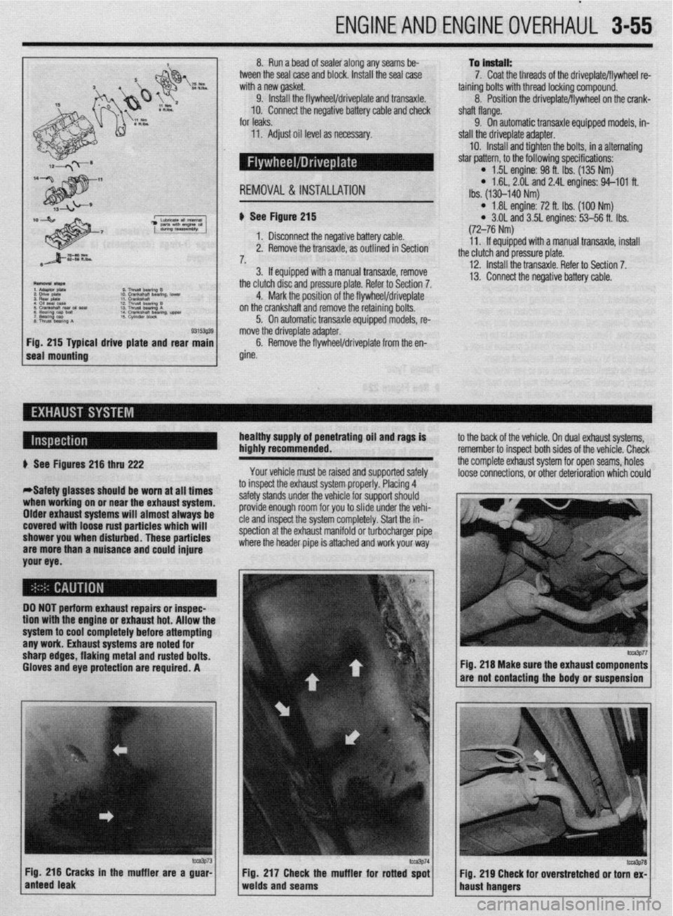
al drive plate and rear b See Figure 215
1. Disconnect the negative battery cable.
2. Remove the transaxle, as outlined in Section
7,
3. If equipped with a manual transaxle, remove
the clutch disc and pressure plate. Refer to Section 7.
4. Mark the position of the flywheel/driveplate
on the crankshaft and remove the retaining bolts.
5. On automatic transaxle equipped models, re-
move the driveplate adapter.
6. Remove the flywheel/driveplate from the en-
gine.
l 1.81 engine: 72 ft. Ibs. (100 Nm) l 3.OL and 3.5L engines: 53-56 ft. Ibs.
(72-76 Nm)
11. If equipped with a manual transaxle, install
the clutch and pressure plate.
12. Install the transaxle. Refer to Section 7.
13. Connect the negative battery cable.
healthy supply of penetrating oil and rags is
highly recommended.
Your vehicle must be raised and supported safely to the back of the vehicle. On dual exhaust systems,
remember to insoect both sides of the vehicle. Check
the complete exhaust system for open seams, holes
loose connections, or other deterioration which could + See Figures 216 thru 222
*Safety glasses should be worn at all times
when working on or near the exhaust system.
Older exhaust systems will almost always be
covered with loose rust particles which will
shower you when disturbed. These particles
are more than a nuisance and could injure
your eye. to inspect the exhaust system properly. Placing 4
safety stands under the vehicle for support should
provide enough room for you to slide under the vehi-
cle and inspect the system completely. Start the in-
spection at the exhaust manifold or turbocharger pipe
where the header pipe is attached and work your way
DO NOT perform exhaust repairs or inspec-
tion wtth the engine or exhaust hot. Allow thr
system to cool completely before attempting
any work. Exhaust systems are noted for
sharp edges, flaking metal and rusted bolts.
Gloves and eye protection are required. A
m3p73 Fig. 216 Cracks in the muffler are a guar-
anteed leak Fig 217 Check the muffler for rotted spot
Fig. 219 Cheek for overstretched or torn ex-
welds and seams
haust hangers
fm3p77 Fig. 216 Make sure the exhaust components
are not contacting the body or suspension
lcca3P78
Page 195 of 408
5-8 FUELSYSTEM
9 ,npimr w1m.m
1: i”“L,
1: 82”w
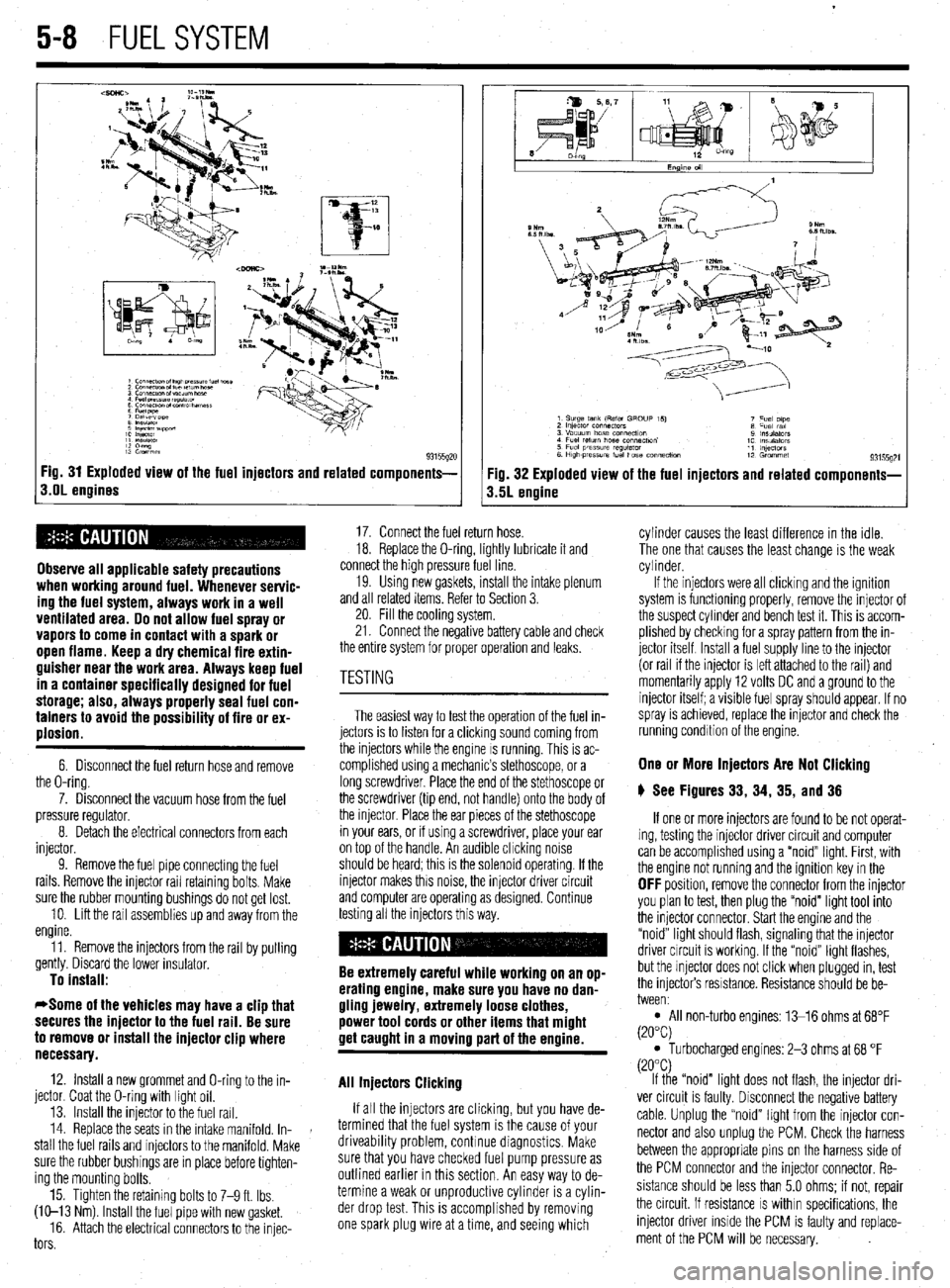
93155gx Fig. 31 Exploded view of the fuel injectors and related components-
s.OL engines
Observe all applicable safety precautions
when working around fuel. Whenever servic-
ing the fuel system, always work in a well
ventilated area. Do not allow fuel spray or
vapors to come in contact with a spark or
open flame. Keep a dry chemical fire extin-
guisher near the work area. Always keep fuel
in a container specifically designed for fuel
storage; also, always properly seal fuel con-
tainers to avoid the possibility of fire or ex-
plosion.
6. Disconnect the fuel return hose and remove
the O-ring.
7. Disconnect the vacuum hose from the fuel
pressure regulator.
8. Detach the electrical connectors from each
injector.
9. Remove the fuel pipe connectmg the fuel
rails. Remove the injector rail retaining bolts. Make
sure the rubber mounting bushings do not get lost.
10. Lift the rail assemblies up and away from the
engine.
11. Remove the injectors from the rail by pulling
gently. Discard the lower insulator.
To install:
*Some of the vehicles may have a clip that
secures the injector to the fuel rail. Be sure
to remove or install the injector clip where
necessary.
12. Install a new grommet and O-ring to the in-
jector. Coat the O-ring with light oil.
13. Install the injector to the fuel rail.
14. Replace the seats in the intake manifold. In-
stall the fuel rails and injectors to the manifold. Make
sure the rubber bushings are in place before tighten-
ing the mounting bolts.
15. Tighten the retaining bolts to 7-9 ft. Ibs.
(W-13 Nm) Install the fuel pipe with new gasket.
16. Attach the electrical connectors to the injec-
tors
Fig. 32 Exploded view of the fuel injectors and related components-
3.5L engine
17. Connect the fuel return hose.
18. Replace the O-ring, lightly lubricate it and
connect the high pressure fuel line.
19. Usmg new gaskets, install the intake plenum
and all related items. Refer to Section 3.
20. Fill the cooling system.
21. Connect the negative battery cable and check
the entire system for proper operation and leaks.
The easiest way to test the operation of the fuel in-
jectors is to listen for a clicking sound coming from
the injectors while the engine IS running. This is ac-
complished using a mechanic’s stethoscope, or a
long screwdriver. Place the end of the stethoscope or
the screwdriver (tip end, not handle) onto the body of
the injector. Place the ear pieces of the stethoscope
in your ears, or if using a screwdriver, place your ear
on top of the handle. An audible chcking noise
should be heard; this is the solenoid operating. If the
injector makes this noise, the injector driver circuit
and computer are operating as designed. Continue
testing all the injectors this way.
Be extremely careful while working on an op-
erating engine, make sure you have no dan-
gling jewelry, extremely loose clothes,
power tool cords or other items that might
get caught in a moving part of the ermine.
All Injectors Clicking
If all the injectors are clicking, but you have de-
termined that the fuel system is the cause of your
driveability problem, continue diagnostics. Make
sure that you have checked fuel pump pressure as
outlined earlier in this section. An easy way to de-
termine a weak or unproductive cylinder is a cylin-
der drop test. This is accomplished by removing
one spark plug wire at a time, and seeing which cylinder causes the least difference in the idle.
The one that causes the least change is the weak
cylinder.
If the injectors were all clicking and the ignition
system is functioning properly, remove the injector of
the suspect cylinder and bench test it. This is accom-
plished by checking for a spray pattern from the in-
jector itself Install a fuel supply line to the injector
(or rail if the injector is left attached to the rail) and
momentarily apply 12 volts DC and a ground to the
injector itself; a visible fuel spray should appear. If no
spray is achieved, replace the injector and check the
running condition of the engine.
One or More Injectors Are Not Clicking
6 See Figures 33, 34, 35, and 36
If one or more injectors are found to be not operat-
ing, testing the injector driver circuit and computer
can be accomplished using a “noid” light. First, with
the engine not running and the ignition key in the
OFF position, remove the connector from the injector
you plan to test, then plug the “noid” light tool into
the injector connector. Start the engine and the
“noid” light should flash, signaling that the injector
driver circuit is working. If the “noid” light flashes,
but the injector does not click when plugged in, test
the injectors resistance. Resistance should be be-
tween:
l All non-turbo engines: 13-16 ohms at 68°F
(20°C)
l Turbocharged engines: 2-3 ohms at 68 “F
(20°C)
If the “noid” light does not flash, the injector dri-
ver circuit is faulty. Disconnect the negative battery
cable. Unplug the “noid” light from the injector con-
nector and also unplug the PCM. Check the harness
between the appropriate pins on the harness side of
the PCM connector and the injector connector. Re-
sistance should be less than 5.0 ohms; if not, repair
the circuit. If resistance
IS within specifications, the
injector driver inside the PCM is faulty and replace-
ment of the PCM will be necessary.
Page 286 of 408
DRlVETRilN 7-7
bansaxle. When the pedal is pushed inward, the disc
and plate separate (the clutch is disenqaqed) discon-
necti
M no the enoine from the transaxie.- .
The clutch driven disc mav comam asoestos.
Galant and Mirage
b See Figures 28 thru 41 ost clutches utilize a single plate, dry friction REMOVAL &INSTALLATION
.* * _ disc with a diaphragm-style spring pressure plate.
which has been determined to be a cancer ’ The clutch disc has a splined hub which attaches the
causing agent. Never clean clutch surfaces disc to the input shaft. The disc has friction material
with compressed air! Avoid inhaling any dust where it contacts the flywheel and pressure plate.
from any clutch surface! When cleaning Torsion springs on the disc help absorb engine
clutch surfaces, use a commercially avail- torque pulses. The pressure plate applies pressure to
able brake cleaning fluid. the clutch disc, holding it tight againstthe surface of
the flywheel. The clutch operating mechanism con-
sists of a release bearing, fork and cylinder assembly. The clutch driven disc may contain asbestos,
The purpose of the clutch is to disconnect and
The release fork and actuating linkage transfer which has been determined to be a cancer
connect engine power at the tram&e. A vehicle at
pedal motion to the release bearing. In the engaged causing agent. Never clean clutch surfaces
rest requires a lot of engine torque to get all that
weight moving. An internal combustion engine does position (pedal released) the diaphragm spring holds with compressed air! Avoid inhaling any dust
the pressure plate against the clutch disc, so engine from any clutch surface! When cleaning
not develop a high starting torque (unlike steam en-
torque is transmitted to the input shaft. When the clutch surfaces, use a commercially avail-
gines) so it must be allowed to operate without any
clutch pedal is depressed, the release bearing pushes able brake cleaning fluid.
load until it builds up enough torque to move the ve-
hicle. Torque increases with engine rpm. The clutch the diaphragm spring center toward the flywheel. The
diaphragm spring pivots the fulcrum, relieving the 1. Disconnect the negative battery cable.
allows the engine to build up torque by physically
disconnecting the engine from the transaxle, relieving load on the pressure plate. Steel spring straps riveted 2. Raise and safely support the vehicle.
the engine of any load or resistance. to the clutch cover lift the pn--“-- -I-‘^ I--- ‘!-- 3. Remove the transaxle assemblv from the ve-
The transfer of engine power to the transaxle (the clutch disc, disengaging the Gllyl,lo UllVc IIVIII II1c
4. Remove the oressure elate attachina bolts.
load) must be smooth and gradual; if it weren’t, drive transaxle and enabling the gc”-- +,, h,n -‘----’
line components would wear out or break quickly. The clutch is operating pryV’uV,J ,,.
l to be reused, loosen the bolts in a diagonal pattern 1
This gradual power transfer is made possible by It will stall the engine when released with the
vehicle held stationary. or 2 turns at a time. This will prevent warping the
gradually releasing the clutch pedal. The clutch disc
l The shift lever can be moved freely between 1st clutch cover assembly.
and pressure plate are the connecting link between
and reverse gears when the vehicle is stationary and 5. Remove the return clip and the pressure plate
the engine and transaxle. When the clutch pedal is
the clutch disengaged. release bearing. Do not use solvent to clean the bear-
released, the disc and plate contact each other (the ing.
clutch is engaged) ohvsicallv ioinina the enaine and 6. lnsoect the clutch release fork and fulcrum for hicle. Refer to the procedure earlier in this section.
pressure plate and clutch disc. If the pressure plate is
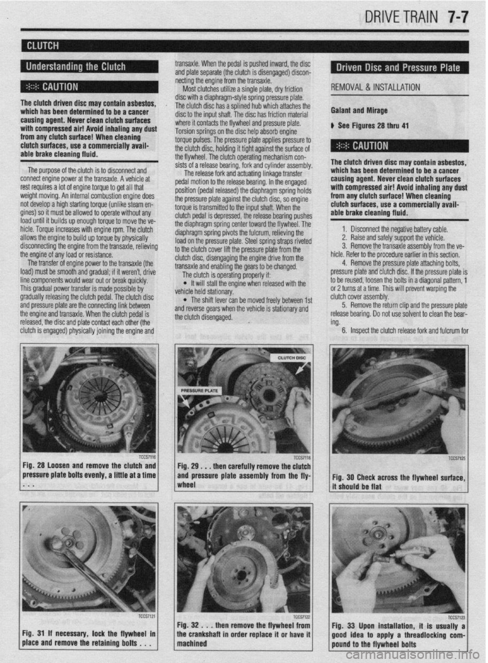
TCCS7118 Fig. 28 Loosen and remove the clutch and
. . . then carefully remove the clutch
essure plate bolts evenly, a little at a time
1~~~~~ -1 [it&ouldbeflat and pressure plate assembly from the fly
- ‘(
1 .
Fig. 33 Upon installation, it is usually a 7 1 / F@%!,d . then remove the flywhee;;:! 1 1 pound’to the flywheel bolts . Tccs7’z3~
Ftg. 31 If necessary, lock the flywheel III
the crankshaft m order replace d or have d
place and remove the retaining bolts . . . good Idea to apply a threadlockmg com-
Page 297 of 408
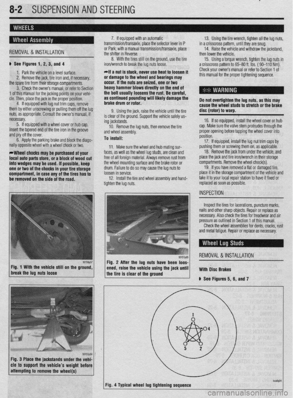
.
8-2 SUSPENSION AND STEERING
b
REMOVAL &INSTALLATION
# See Figures 1, 2, 3, and 4
1. Park the vehicle on a level surface.
2. Remove the jack, tire iron and, if necessary,
the spare tire from their storage compartments.
3. Check the owners manual, or refer to Section
1 of this manual for the jacking points on your vehi-
cle. Then, place the jack in the proper position,
4. If equipped with lug nut trim caps, remove
them by either unscrewing or pulling them off the lug
nuts, as appropriate. Consult the owners manual, if
necessary.
5. If equipped with a wheel cover or hub cap,
insert the tapered end of the tire iron in the groove
and pry off the cover.
6. Apply the parking brake and block the diago-
nally opposite wheel with a wheel chock or two.
*Wheel chocks may be purchased at your
local auto parts store, or a block of wood cut
into wedges may be used. If possible, keep
one or two of the chocks in your tire storage
compartment, in case any of the tires has to
be removed on the side of the road. 7. If equipped with an automatic
transmission/transaxle, place the selector lever in P
or Park; with a manual transmission/transaxle, place
the shifter in Reverse.
8. With the tires still on the ground, use the tire
iron/wrench to break the lug nuts loose.
*If a nut is stuck, never use heat to loosen it
or damage to the wheel and bearings may
occur. If the nuts are seized, one or two
heavy hammer blows directly on the end of
the bolt usually loosens the rust. Be careful,
as continued pounding will likely damage the
brake drum or rotor.
9. Using the jack, raise the vehicle until the tire
is clear of the ground. Support the vehicle safely us-
ing jackstands.
10. Remove the lug nuts, then remove the tire
and wheel assembly.
To install:
11. Make sure the wheel and hub mating sur-
faces, as well as the wheel lug studs, are clean and
free of all foreign material. Always remove rust from
the wheel mounting surface and the brake rotor or
drum. Failure to do so may cause the lug nuts to
loosen in service.
12. Install the tire and wheel assembly and hand-
tighten the lug nuts. 13. Using the tire wrench, tighten all the lug nuts,
in a crisscross pattern, until they are snug.
14. Raise the vehicle and withdraw the jackstand,
then lower the vehicle.
15. Using a torque wrench, tighten the lug nuts in
a crisscross pattern to 65-80 ft. lbs. ( 90-l 10 Nm).
Check your owners manual or refer to Section 1 of
this manual for the proper tightening sequence.
Do not overtighten the lug nuts, as this may
cause the wheel studs to stretch or the brake
disc (rotor) to warp.
16. If so equipped, install the wheel cover or hub
cap. Make sure the valve stem protrudes through the
proper opening before tapping the wheel cover into
position.
17. If equipped, install the lug nut trim caps by
pushing them or screwing them on, as applicable.
18. Remove the jack from under the vehicle, and
place the jack and tire iron/wrench in their storage
compartments. Remove the wheel chock(s).
19. If you have removed a flat or damaged tire,
place it in the storage compartment of the vehicle and
take it to your local repair station to have it fixed or
replaced as soon as possible.
Inspect the tires for lacerations, puncture marks,
nails and other sharp objects. Repair or replace as
necessary. Also check the tires for treadwear and air
pressure as outlined in Section 1 of this manual.
Check the wheel assemblies for dents, cracks, rust
and metal fatigue. Repair or replace as necessary.
REMOVAL&INSTALLATION
Fig. 3 Place the jackstands under the vehi-
cle to support the vehicle’s weight before
Page 380 of 408
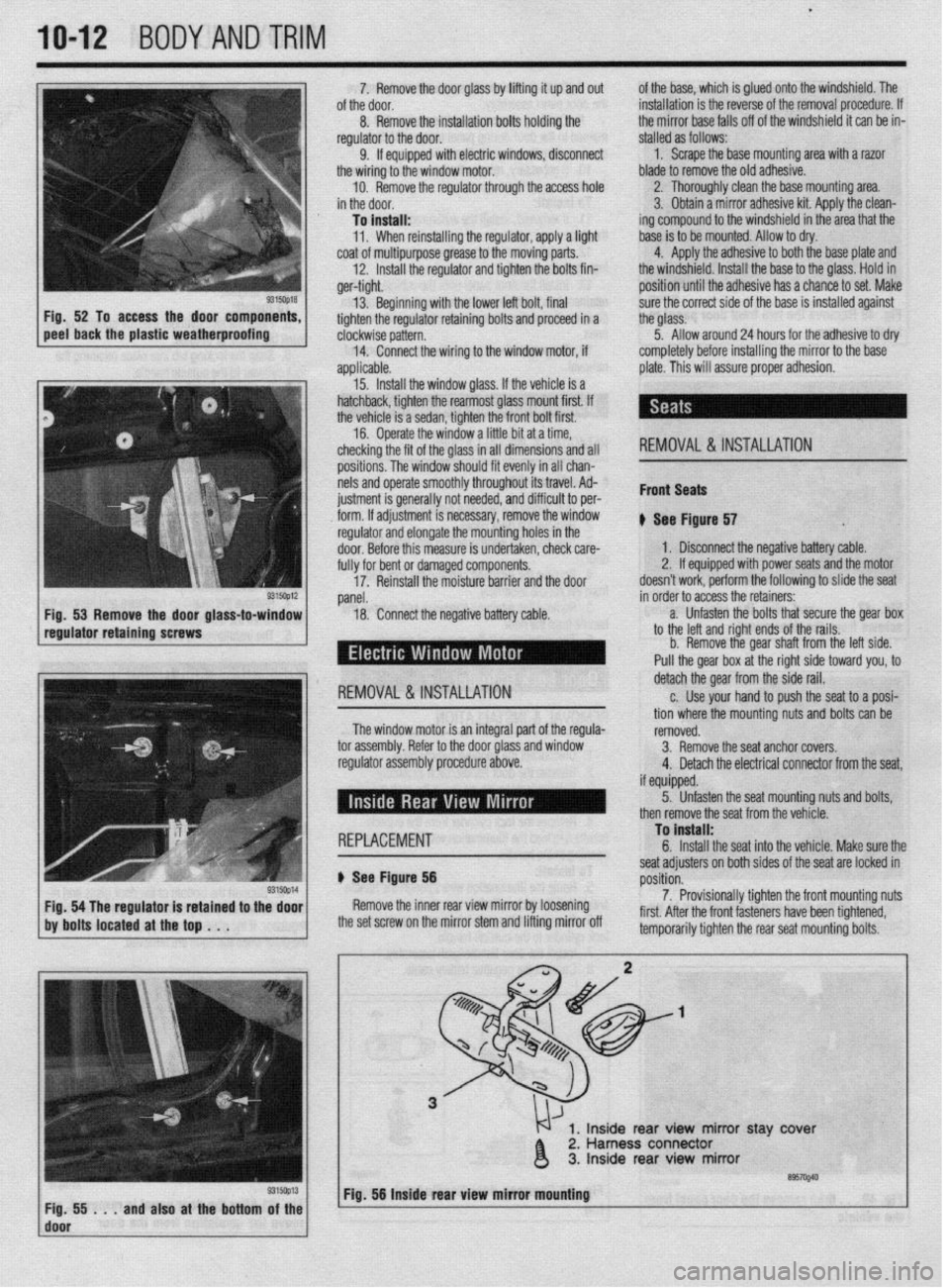
.
1042 BODYANDTRIM
P
I. i%lllUVt: LIE UUUI yldbb Uy lllllll!J It up ana out ot me ease, wnicn IS glueo onto tne wmasnlela. 1 ne
of the door.
installation is the reverse of the removal procedure. If
8. Remove the installation bolts holding the
the mirror base falls off of the windshield it can be in-
regulator to the door.
stalled as follows:
I
9. If equipped with electric windows discnnnad
1. Scrape the base mounting area with a razor
LllC vvllllly L” t,te Wlll”“W lll”l”l.
blade to remove the old adhesive.
I 10. Remove the regulator through the access hole
2. Thoroughly clean the base mounting ara.
’ in the door.
3. Obtain a mirror adhesive kit. Apply the clean-
To install:
ing compound to the windshield in the area that the
11. When reinstalling the regulator, apply a light
base is to be mounted. Allow to dry.
coat of multipurpose grease to the moving parts.
4. Apply the adhesive to both the base plate and
12. Install the regulator and tighten the bolts fin-
the windshield. Install the base to the glass. Hold in
ger-tight.
position until the adhesive has a chance to set. Make
5315oQ18 Fig. 52 To access the door components,
peel back the plastic weatherproofing 13. Beginning with the lower left bolt, final
tighten the regulator retaining bolts and p
clockwise pattern.
14.
applic
+r roceed in a
Connect the wiring to the window motor, if
able.
Install the window glass. If the vehicle is a
lack, tighten the rearmost glass mount first. If
hicle is a sedan, tighten the front bolt first.
.
13. hatcht
the ve’
16. Uperate the window a little bit at a time,
checking the fit of the glass in all dimensions and all
positions. The window should fit evenly in all chan-
nels and operate smoothly throughout its travel. Ad-
ius~ment is rener;IIIv not needed. and diffirlllf +n nor- . ._ ~ _.._. - ., _.
___.-, - - _ lll”“ll I” pm
i&h. If adiustment is necessarv, remove thp win&N I..” . . . ..“1.. regulator and elongate the mointing holes in the
door. Before this measure is undertaken, check care-
fully for bent or damaged components.
17. Reinstall the moisture barrier and the door sure the correct side of the base is installed against
the glass.
5. Allow around 24 hours for the adhesive to dry
completely before installing the mirror to the base
plate. This will assure proper adhesion.
REMOVAL & INSTALLATION
Front Seats
* err ei
I ovv rlgure 57 .
1, Disconnect the negative battery cable.
2. If equipped with power seats and the motor
doesn’t work, perform the following to slide the seat
panel.
18. Conned the negative battery Cable. in order to acdess the retainers:
-
a. Unfasten the bolts that secure the gear box
to the left and right ends of the rails.
b. Remove the gear shaft from the left side.
Pull the gear box at the right side toward you, to
I REMOVAL & INSTALLATION detach the gear from the side rail.
c. Use your hand to push the seat to a posi-
tion where the mounting nuts and bolts can be
The window motor is an integral part nf the renlrla-
romnvPrl
-’ .“- ‘-J-.- tor assembly. Refer to the door Glass and window
regulator assembly procedure above. IYII,“.““. 3. Remove the seat anchor covers.
4. Detach the electrical connector from the seat,
if m~innd I I, “y”y~Y”. 5. Unfasten the seat mountina nuts and bolts.
1 REPLACEMENT To install:
c
b Ser f Floure 56
Yap- ~~
Remove the inner rear view mirror by loosening
the set screw on the mirror stem and lifting mirror off seat adjusters on both sides of the seat are locked in
rmritinn p”3111”ll.
7. Provisionally tighten the front mounting nuts
first. After the front fasteners have been tightened,
tomnnr.,rilw tinhton thn co.-ar co.,+ m qunting bolts. then remove the seat from the vehicle.
1, Inside rear view mirror stay ‘cover
2. Harness connector
3. Inside rear view mirror
’ ~;f!i!i...andalsoatthebottom~~~~ Fig. 56 Inside rear view mirror mbuntlng
I