1900 MITSUBISHI DIAMANTE spark plugs replace
[x] Cancel search: spark plugs replacePage 1 of 408
HOW TO USE THIS BOOK 1-2
WHERE TOBEGIN l-2
AVOIDINGTROUBLE 1-2
MAINTENANCEORREPAIR? 1-2
AVOIDINGTHEMOSTCOMMONMISTAKES l-2
TOOLS AND EQUIPMENT 1-2
SPECIALTOOLS l-4
YOUR VEHICLE SAFELY 1-4
DON'TS l-6
FASTENERS, MEASUREMENTS AND
CONVERSIONS l-6
BOLTS,NUTSANDOTHERTHREADED
RETAINERS 1-6
TORQUE l-7
TORQUEWRENCHES l-7
TORQUEANGLEMETERS 1-9
STANDARDANDMETRIC MEASUREMENTS l-9
SERIAL NUMBER IDENTIFICATION l-10
VEHICLE IDENTIFICATION NUMBER l-10
ENGINE IDENTIFICATION NUMBER I-10
TRANSAXLEIDENTIFICATION I-10
DRlVEAXLE(AWDGALANTONLY) l-10
TRANSFERCASE(AWDGALANTONLY) l-10
ROUTINE MAINTENANCE AND TUNE-UP l-14
AIRCLEANER(ELEMENT) 1-14
REMOVAL&INSTALLATION 1-14
FUELFILTER 1-15
REMOVAL &INSTALLATION l-15
PCVVALVE l-15
REMOVAL&INSTALLATION l-15
EVAPORATIVECANISTER l-16
SERVICING 1-16
BATTERY 1-16
PRECAUTIONS I-16
GENERALMAINTENANCE 1-16
BEL BATTERYFLUID 1-16
CABLES I-17
CHARGING I-18
REPLACEMENT 1-18
TS 1-18
INSPECTiON l-18
ADJUSTMENT 1-18
REMOVAL&INSTALLATION 1-18
TIMINGBELTS l-20
INSPECTION l-20
HOSES I-20
INSPECTION l-20
REMOVAL&INSTALLATION
CV-BOOTS 1-21
INSPECTION l-21
SPARKPLUGS l-22
SPARKPLUGHEATRANGE
REMOVAL&INSTALLATION
INSPECTION &GAPPING 1.
SPARKPLUG WIRES 1-24
TESTING 1-24
REMOVAL&INSTALLATION
DISTRIBUTORCAPANDROTOR
REMOVAL&INSTALLATION
INSPECTION 1-25
IGNITIONTIMING 1-25
. GENERALINFORAMTION l-
lNSPECTlON&ADJUSTMENl
VALVE LASH l-27
ADJUSTMENT l-27
IDLESPEED 1-28 1-21
l-22
l-22
-23
1-24
l-25
l-25
.25
1-26
AIR CONDITIONING SYSTEM 1-28
SYSTEMSERVlCEiiREPAlR l-28
PREVENTIVEMAINTENANCE 1-28
SYSTEM INSPECTION l-29
WINDSHIELD WIPERS l-29
ELEMENT(REFILL)CARE&
REPLACEMENT l-29
TIRESANDWHEELS l-30
TIRE ROTATION I-30
TIRE DESIGN 1-31
TIRESTORAGE l-31
INFLATION &INSPECTION l-31
CARE OFSPECIALWHEELS l-32 OPERATION INFOREIGNCOUNTRIES l-33
ENGINE l-33
OILLEVELCHECK 1-33
OIL& FILTER CHANGE l-34
MANUALTRANSAXLE l-35
FLUIDRECOMMENDATIONS l-35
LEVELCHECK l-35
DRAIN&REFILL l-36
AUTOMATICTRANSAXLE l-36
FLUIDRECOMMENDATIONS l-36
LEVELCHECK 1-36
DRAIN&REFILL l-36
PAN & FILTERSERVICE 1-36
TRANSFERCASE(AWDGAlANT ONLY) l-38
FLUIDRECOMMENDATIONS l-38
LEVELCHECK l-38
DRAIN&REFILL l-38
REARDRlVEAXLE(AWDGALANTONLY) l-38
FLUIDRECOMMENDATIONS l-38
LEVELCHECK l-38
DRAIN&REFILL l-38
COOLINGSYSTEM l-39
FLUIDRECOMMENDATIONS l-39
iM-41
FLUIDS AND LUBRICANTS 1-33
FLUID DISPOSAL 1-33
FlJELANDENGlNEOILRECOMMENDATlONS
ENGINE OIL l-33
FUEL l-33
Page 2 of 408
.
1-2 GENERALINFORMATIONAND MAINTENANCE
Chitton’s Total Car Care manual for the 199M10
Mitsubishi Mirage, Galant and Diamante is intended
to help you learn more about the inner workings of
your vehicle while saving you money on its upkeep
and operation.
The beginning of the book will likely be referred to
the most, since that is where you will find information
for maintenance and tune-up. The other sections deal
with the more complex systems of your vehicle. Oper-
ating systems from engine through brakes are cov-
ered to the extent that the average do-it-yourselfer be-
comes mechanically involved. This book will not
explain such things as rebuilding a differential for the
simple reason that the expertise required and the in-
vestment in special tools make this task uneconomi-
cal. It will, however, give you detailed instructions to
help you change your own brake pads and shoes, re-
place spark plugs, and perform many more jobs that
can save you money, give you personal satisfaction
and help you avoid expensive problems.
A secondary purpose of this book is a reference for
owners who want to understand their vehicle and/or
their mechanics better. In this case, no tools at all are
required.
Before removing any bolts, read through the entire
procedure. This will give you the overall view of what
tools and supplies will be required. There is nothing
more frustrating than having to walk to the bus stop
on Monday morning because you were short one bolt
on Sunday afternoon. So read ahead and plan ahead.
Each operation should be approached logically and
all procedures thoroughly understood before attempt-
ing any work.
All sections contain adjustments, maintenance, re-
moval and installation procedures, and in some cases,
repair or overhaul procedures. When repair is not con-
sidered practical, we tell you how to remove the part
and then how to install the new or rebuilt replacement.
In this way, you at least save labor costs. “Backyard”
repair of some components is just not practical.
Many procedures in this book require you to “label
and disconnect. . ” a group of lines, hoses or wires.
Don’t be lulled into thinking you can remember where
everything goes-you won’t. If you hook up vacuum
or fuel lines incorrectly, the vehicle may run poorly, if
at all. If you hook up electrical wiring incorrectly, you
may instantly learn a very expensive lesson.
You don’t need to know the official or engineering
name for each hose or line. A piece of masking tape
on the hose and a piece on its fitting will allow you to
assign your own label such as the letter A or a short name. As long as you remember your own code, the
lines can be reconnected by matching similar letters
or names. Do remember that tape will dissolve in
gasolrne or other fluids; if a component is to be
washed or cleaned, use another method of identifica-
tion. A permanent felt-tipped marker or a metal scribe
can be very handy for marking metal parts. Remove
any tape or paper labels after assembly.
It’s necessary to mention the difference between
maintenance and repair Maintenance includes rou-
tine inspections, adjustments, and replacement of
parts which show signs of normal wear Maintenance
compensates for wear or deterioration. Repair implies
that something has broken or is not working. A need
for repair is often caused by lack of maintenance. Ex-
ample, draining and refilling the automatic transaxle
fluid is maintenance recommended by the manufac-
turer at specific mileage intervals. Failure to do this
can shorten the life of the transmission/transaxle, re-
quiring very expensive repairs. While no maintenance
program can prevent items from breaking or wearing
out, a general rule can be stated: MAINTENANCE IS
CHEAPER THAN REPAIR.
Two basic mechanrc’s rules should be mentioned
here. First, whenever the left side of the vehicle or en-
gine is referred to, it is meant to specify the drivers
side. Conversely, the right side of the vehicle means
the passengers side. Second, screws and bolts are
removed by turning counterclockwise, and tightened
by turning clockwrse unless specifically noted.
Safety is always the most important rule. Con-
stantly be aware of the dangers involved in working
on an automobile and take the proper precautions.
See the informatron in this section regarding SER-
VICING YOUR VEHICLE SAFELY and the SAFETY
NOTICE on the acknowledgment page.
Pay attention to the instructions provided. There
are 3 common mistakes in mechanical work:
1. Incorrect order of assembly, disassembly or
adjustment. When taking something apart or putting
it together, performing steps in the wrong order usu-
ally just costs you extra time; however, it CAN break
something. Read the entire procedure before begin-
ning disassembly. Perform everything in the order in
which the instructions say you should, even if you
can’t immedrately see a reason for it. When you’re
taking apart something that is very intricate, you
might want to draw a picture of how it looks when as-
sembled at one point in order to make sure you get everything back in its proper position. We will supply
exploded views whenever possible. When making
adjustments, perform them in the proper order. One
adjustment possibly will affect another.
2. Overtorquing (or undertorquing). While it is
more common for overtorquing to cause damage,
undertorquing may allow a fastener to vibrate loose
causing serious damage. Especially when dealing
with aluminum parts, pay attention to torque specifi-
cations and utilize a torque wrench in assembly. If a
torque figure is not available, remember that if you
are using the right tool to perform the job, you will
probably not have to strain yourself to get a fastener
tight enough. The pitch of most threads is so slight
that the tension you put on the wrench will be multi-
plied many times in actual force on what you are
tightening. A good example of how critical torque is
can be seen in the case of spark plug installation, es-
pecially where you are putting the plug into an alu-
minum cylinder head. Too little torque can fail to
crush the gasket, causing leakage of combustion
gases and consequent overheating of the plug and
engine parts. Too much torque can damage the
threads or distort the plug, changing the spark gap.
There are many commercial products available for
ensuring that fasteners won’t come loose, even if they
are not torqued just right (a very common brand is
Loctite? If you’re worried
about getting something
together tight enough to hold, but loose enough to
avoid mechanical damage during assembly, one of
these products might offer substantial insurance. Be-
fore choosing a threadlocking compound, read the
label on the package and make sure the product is
compatible with the materials, fluids, etc. involved.
3. Crossthreading. This occurs when a part such
as a bolt is screwed into a nut or casting at the wrong
angle and forced. Crossthreading is more likely to
occur if access is difficult. It helps to clean and lubri-
cate fasteners, then to start threading the bolt, spark
plug, etc. with your fingers If you encounter resis-
tance, unscrew the part and start over again at a dif-
ferent angle until it can be inserted and turned several
times without much effort. Keep in mind that many
parts, especially spark plugs, have tapered threads,
so that gentle turning will automatically bring the part
you’re threading to the proper angle. Don’t put a
wrench on the part until its been tightened a couple
of turns by hand. If you suddenly encounter resis-
tance, and the part has not seated fully, don’t force it.
Pull it back out to make sure it’s clean and threading
properly.
Be sure to take your time and be patient, and al-
ways plan ahead. Allow yourself ample time to per-
form repairs and maintenance You may find main-
taining your car a satisfying and enjoyable
experience.
b See Figures 1 thru 15
Naturally, without the proper tools and equipment
it is impossible to properly service your vehicle. It
would also be virtually impossible
to catalog every
tool that you would need to perform all of the opera-
tions in this book. Of course, It would be unwise for
the amateur to rush out and buy an expensive set of
tools on the theory that he/she may need one or more
of them at some time, The best approach is to proceed slowly, gathering savings will
be far outweighed by frustration and
a good quality set of those tools that are used most mangled knuckles.
frequently Don’t be misled by the low cost of bargain Begin accumulating those tools that are used most
tools. It is far better to spend a little more for better frequently: those associated with routine maintenance
quality. Forged wrenches, 6 or 12-point sockets and and tune-up. In addition to the normal assortment of
fine tooth ratchets are by far preferable to their less screwdrivers and pliers, you should have the follow-
expensive counterparts. As any good mechanic can ing tools:
tell you, there are few worse experiences than trying
l Wrenches/sockets and combination open
to work on a vehicle with bad tools. Your monetary end/box end wrenches in sizes from %-% in. or
Page 21 of 408
l-22 GENERALINFORMATIONAND MAINTENANCE
tears. If the boot is damaged, it should be replaced
trode is to the block’s cooling passages) the cooler it
your driving is long distance, high speed travel, use a
immediately. Please refer to Section 7 for procedures.
will operate. A plug that absorbs little heat and re-
colder plug; if most of your driving is stop and go,
mains too cool will quickly accumulate deposits of
use a hotter plug. Original equipment plugs are gen-
oil and carbon since it is not hot enough to burn
erally a good compromise between the 2 styles and
them off. This leads to plug fouling and consequently
most people never have the need to change their
to misfiring. A plug that absorbs too much heat will
plugs from the factory-recommended heat range.
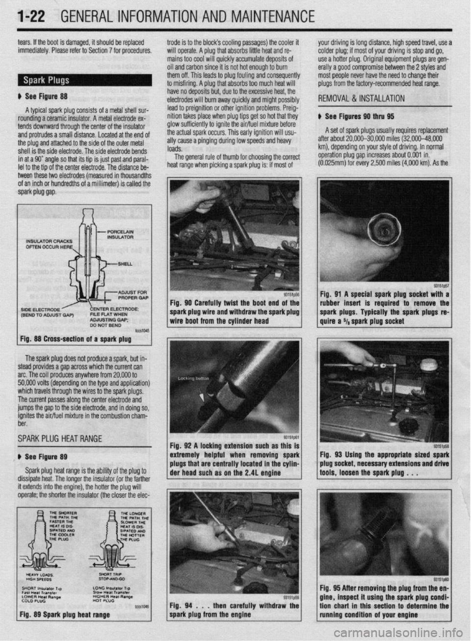
ti See Figure 88 have no deposits but, due to the excessive heat, the
,electrodes will burn away quickly and might possibly
REMOVAL &INSTALLATION
A typical spark plug consists of a metal shell sur- lead to preignition or other ignition problems. Preig-
rounding a ceramic insulator. A metal electrode ex- nition takes place when plug tips get so hot that they
ti See Figures 90 thru 95
tends downward through the center of the insulator glow sufficiently to ignite the air/fuel mixture before
and protrudes a small distance. Located at the end of the actual spark occurs. This early ignition will usu- A set of spark plugs usually requires replacement
the plug and attached to the side of the outer metal ally cause a pinging during low speeds and heavy after about 20,000-30,000 miles (32,000-48,000
shell is the side electrode. The side electrode bends loads. km), depending on your style of driving. In normal
in at a 90” angle so that its tip is just past and paral- The general rule of thumb for choosing the correct operation plug gap increases about 0.001 in.
lel to the tio of the center electrode. The distance be- heat range when picking a spark plug is: if most of (0.025mrn) for every 2,500 miles
(4,000 km). As the
tween these two electrodes (measured in thousandths
of an inch or hundredths of a millimeter) is called the
spark piug gap.
The spark plug does not produce a spark, but in-
steed provides a gap across which the current can
arc. The coil produces anywhere from 20,000 to
50,000 volts (depending on the type and application)
which travels through the wires to the spark plugs.
The current passes along the center electrode and
jumps the gap to the side electrode, and in doing so,
ignites the air/fuel mixture in the combustion charn-
ber.
SPARKPLUG HEATRANGE
ti See Figure 89
Spark plug heat range is the ability of the plug to
dissipate heat. The longer the insulator (or the farther
INSULATOR CRACKS
OFTEN OCCUR HERE
SIDE ELECTRODE ENTER ELECTRODE:
(SEND TO ADJUST GAP) FILE FLAT WHEN
ADJUSTING GAP;
DO NOT BEND
Fig. 88 Cross-section of a spark plug
it extends into the engine), the hotter the plug will
operate; the shorter the insulator (the closer the elec- Fig. 90 Carefully twist the boot end of the
I
spark plug wire and withdraw the spark plug
wire boot from the cylinder head
Fig. 92 A locking extension such as this is
extremely helpful when removing spark
plugs that are centrally located in the cyhn-
Fig. 94 . . .
then carefully withdraw the
spark plug from the engine Fig. 91 A special spark plug socket with a
rubber insert is required to remove the
spark plugs. Typically the spark plugs
re-
quire a Ya spark plug socket
Fig, 93 Using the appropriate sized spark
plug socket, necessary extensions and drive
tools, loosen the spark plug . . .
93151ptxl Fig. 95 After removing the plug from the en-
gine, inspect it using the spark plug condi-
tion chart in this section to determine the
running condition of your engine
Page 22 of 408
t
GENERALINFORMATIONAND MAINTENANCE l-23
gap increases, the plug’s voltage requirement also in-
creases. It requires a greater voltage to jump the the spark plug counterclockwise to loosen and re-
move the spark plug from the bore.
wider gap and about &o to three times as much volt-
age to fire the plug at high speeds than at idle. The
improved air/fuel ratio control of modern fuel injec-
tion combined with the higher voltage output of mod- Be sure not to use a flexible extension on the place. The click may be felt or heard, then gently pull
ern ignition systems will often allow an engine to run socket. Use of a flexible extension may allow back on the boot to assure proper contact.
.___. . _
significantly longer on a set of standard spark plugs, a shear force to be agptf’ ea to me plug.
A 12. On the 3.OL fSOHC and DOHC) and 3.5L en-
LL_ _I___ -u I_ IL-
but keep in mind that efficiency will drop as the gap shear force could break tne pug on III me
tion 3 for the installation procedure.
widens (along with fuel economy and power). cylinder head, leading to costly and frustrat-
13. If equipped, install the center cover.
When you’re removing spark plugs, work on one ing repairs.
at a time. Don’t start by removing the plug wires all at
once, because, unless you number them, they may To install:
INSPECTION & GAPPING
11. Apply a small amount of silicone dielectric
compound to the end of the spark plug lead or inside
the spark plug boot to prevent sticking, then install
the boot to the spark plug and push until it clicks into
gines, install the upper intake manifold. Refer to Sec-
,,Y” ..1111 uy”’ 1 the neaative bat&v cable and if become mixed up. Take a minute before you begin
and number the wrrpc with +sne
1. Disconnect. ~~.~
--..-., -..-.-, -..-
thevehicle has been run recently, allow the engine to
thoroughly cool.
2. If equipped, remove the center cover.
3. On the 3.OL (SOHC and DOHC) and 3.5L en-
gines, the upper intake manifold must be removed to
access the rear spark plugs. Refer to Section 3 for the
removal procedure.
4. Carefully twist the spark plug wire boot to
loosen it, then pull upward and remove the boot from
the plug. Be sure to pull on the boot and not on the
wire, otherwise the connector located inside the boot
may become separated.
5. Using compressed air, blow any water or de-
bris from the spark plug well to assure that no harm-
ful contaminants are allowed to enter the combustion
chamber when the spark plug is removed. If com-
pressed air is not available, use a raa or a brush to must be replaced.
Check the plugs for deposits and wear, If they are 7. Inspect the spark plug boot for tears or dam-
age. If.a damaged boot is found, the spark plug wire
8. Using a wire feelergauge, check and adjust
the spark plug gap. When using a gauge, the proper
size should pass between the electrodes with a slight
drag. The next larger size should not be able to pass
while the next smaller size should pass freely.
9. Carefully thread the plug into the bore by
hand. If resistance is felt before the plug is almost
completely threaded, back the plug out and begin
threading again. In small, hard to reach areas, an old
spark plug wire and boot could be used as a thread-
ing tool. The boot will hold the plug while you twist
the end of the wire and the wire is supple enough to
twist before it would allow the plug to crossthread.
Do not use the spark plug sock?
l -- K-rrA tha nhme Alwmm rarntdlv thw GL I” IlllGa”
the possibility of crossthreading and damag- lad the plug
. ..Y f..“YY. rn”Y,‘““mY*“.‘, .I**” by hand or using an old plug wire to prevent
ing the cylinder head bore.
10. Carefully tighten the spark plug. If the plug
you are installing is equipped with a crush washer,
seat the plug, then tighten about I/, turn to crush the
washer. If you are installing a tapered seat plug,
tighten the plug to specifications provided by the ve-
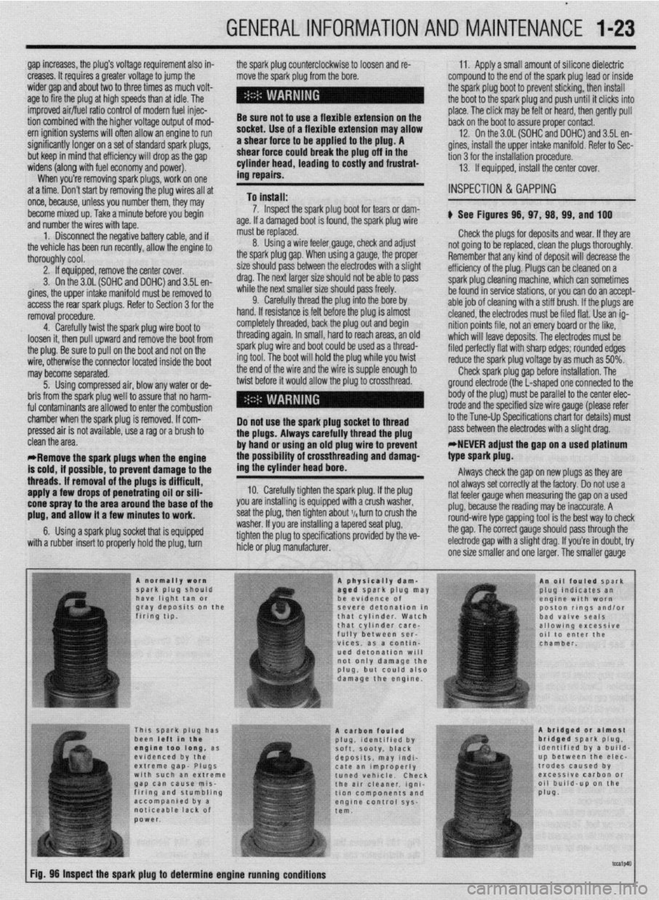
hicle or plug manufacturer. b See Figures 98, 97, 98, 99, and 100
not going to be replaced, clean the plugs thoroughly.
Remember that any kind of deposit will decrease the
efficiency of the plug. Plugs can be cleaned on a
spark plug cleaning machine, which can sometimes
be found in service stations, or you can do an accept-
able job of cleaning with a stiff brush. If the plugs are’
cleaned, the electrodes must be filed flat. Use an ig-
nition points file, not an emery board or the like,
which will leave deposits. The electrodes must be
filed perfectly flat with sharp edges; rounded edges
reduce the spark plug voltage by as much as 50%.
Check spark plug gap before installation. The
ground electrode (the L-shaped one connected to the
body of the plug) must be parallel to the center elec-
trode and the specified size wire gauge (please refer
to the Tune-Up Specifications chart for details) must
pass between the electrodes with a slight drag:
*,NEVER adjust the gap on a used platinum
. clean the area.
*Remove the spark plugs when the engine
is cold, if possible, to prevent damage to the
threads. If removal of the plugs is difficult,
apply a few drops of penetrating oil or sili-
cone spray to the area around the base of the
plug, and allow it a few minutes to work.
6. Using a spark plug socket that is equipped
with a rubber insert to properly hold the plug, turn type spark plug.
Always check the gap on new plugs as they are
not always set correctly at the factory. Do not use a
flat feeler gauge when measuring the gap on a used
plug, because the reading may be inaccurate. A
round-wire type gapping tool is the best way to check
the gap. The correct gauge should pass through the
electrode gap with a slight drag. If you’re in doubt, try
one size smaller and one laraer. The smaller aauqe
Page 23 of 408
l-24 GENERALINFORMATIONAND MAINTENANCE
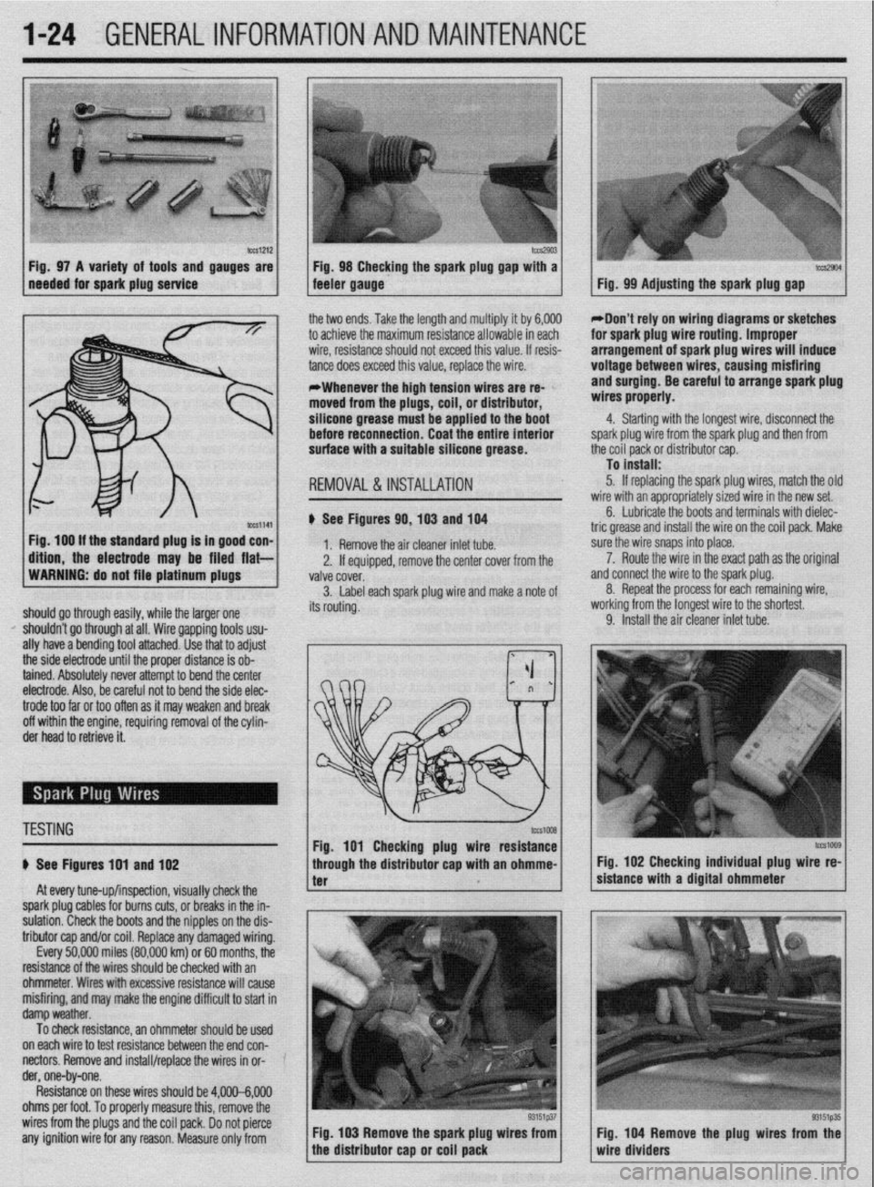
b%slZl2 Fig. 97 A variety of tools and gauges are
needed for spark plug service tm2903 Fig. 98 Checking the spark plug @au with a tccs2904 feeler gauge. - Fig. 99 Adjusting the spark plug gap
ig. 100 If the standard plug Is in good con-
ftlon, the electrode may be filed flat- the two ends. Take the length and multiply it by 6,000
to achieve the maximum resistance allowable in each
wire, resistance should not exceed this value. If resis-
tance does exceed this value, replace the wire.
*Whenever the high tension wires are re- ’
moved from the plugs, coil, or distributor,
silicone grease must be applied to the boot
before reconnection. Coat the entire Interior
surface with a suitable silicone grease.
REMOVAL &INSTALLATION
# See Figures 90,103 and 104
1. Remove the air cleaner inlet tube.
2. If eouiooed, remove the center cover from the
WARNING: do not file platinum plugs
valve covei.
3. Label each spark plug wire and make a note of
should go through easily, while the larger one its routing.
I’ shouldn’t go through at all. Wire gapping tools usu-
ally have a bending tool attached. Use that to adjust
the side electrode until the proper distance is ob-
tained. Absolutely never attempt to bend the center
electrode. Also, be careful not to bend the side elec- *Don’t rely on wiring diagrams or sketches
for spark plug wire routing. Improper
arrangement of spark plug wires will induce
voltage between wires, causing misfiring
and surging. Be careful to arrange spark plug
wires properly.
4. Starting with the longest wire, disconnect the
spark plug wire from the spark plug and then from
the coil pack or distributor cap.
To install:
5. If replacing the spark plug wires, match the olc
wire with an appropriately sized wire in the new set.
6. Lubricate the boots and terminals with dielec-
tric grease and install the wire on the coil pack. Make
sure the wire snaps into place.
a 7. Route the wire in the exact path as the original
nd connect the wire to the spark plug.
8. Repeat the process for each remaining wire,
iorking from the longest wire to the shortest.
9. Install the air cleaner inlet tube.
trode too far or too often as it may weaken and break
off within the engine, requiring removal of the cylin-
der head to retrieve it.
TESTING
# See Figures 191 and 102
At every tune-up/inspection, visually check the
spark plug cables for burns cuts, or breaks in the in-
sulation. Check the boots and the nipples on the dis-
tributor cap and/or coil. Replace any damaged wiring.
Every 50,000 miles (80,000 km) or 60 months, the
resistance of the wires should be checked with an
ohmmeter. Wires with excessive resistance will cause
misfiring, and may make the engine difficult to start in
damp weather.
To check resistance, an ohmmeter should be used ’
on each wire to test resistance between the end con-
nectors. Remove and install/replace the wires in or- ’
der, one-by-one.
Resistance on these wires should be 4,000-6,000
ohms per foot. To properly measure this, remove the
wires from the plugs and the coil pack. Do not pierce
any ignition wire for any reason. Measure only from Fig. 103 Remove the spark plug wires from
tcG1009 Fig. 102 Checking individual plug wire re-
sistance with a digital ohmmeter
Fig. 104 Remove the plug wires from the
wire dividers
Page 24 of 408
GENERALINFORMATIONAND MAlNTENANdE 1-25
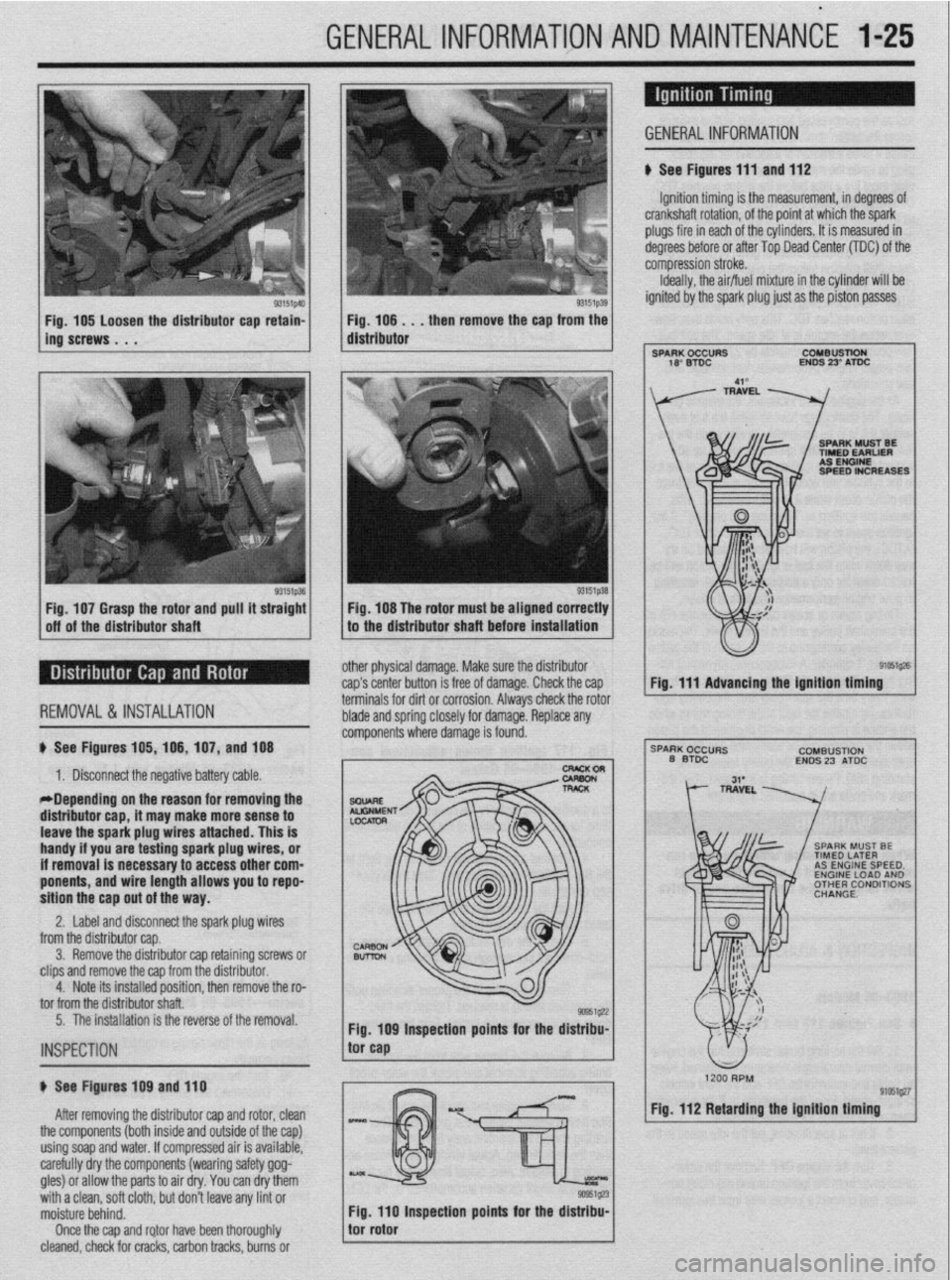
osen the distributor cap retain-
Fig. 106. . . then remove the cap from the
distributor
Fig. 107 Grasp the rotor and pull it straight
off of the distributor shaft
REMOVAL &INSTALLATION
1. Disconnect the negative battery cable.
*Depending on the reason for removing the
distributor cap, it may make more sense to Fig. 108 The rotor must be aligned correctly
to the distributor shaft before installation
other physical damage. Make sure the distributor
cap’s center button is free of damage. Check the cap
terminals for dirt or corrosion. Always check the rotor
blade and spring closely for damage. Replace any
comoonents where damaae is found.
smmE
ALGNME
LOCATOR
b See Figures 105,106,107, and 108 GENERAL INFORMATION
b See Figures 111 and 112
Ignition timing is the measurement, in degrees of
crankshaft rotation, of the point at which the spark
plugs fire in each of the cylinders. It is measured in
degrees before or after Top Dead Center (TDC) of the
compression stroke.
Ideally, the air/fuel mixture in the cylinder will be
ignited by the spark plug just as the piston passes
I 1 COMBUSTION
ENDS 23’ ATDC
SPEED INCREASES
9ir&1$?6
Fig. 111 Advancing the ignition timing
’
CCURS
COMBUSTION
DC
ENDS 23 ATDC
3. Remove the distributor cap retaining screws or
clips and remove the cap from the distributor.
4. Note its installed position, then remove the ro-
tor from the distributor shaft. leave the spark plug wires attached. This is
handy if you are testing spark plug wires, or
if removal is necessary to access other com-
ponents, and wire length allows you to repo-
sition the cap out of the way.
2. Label and disconnect the spark plug wires
from the distributor cao.
5. The installation is the reverse of the removal.
INSPECTION
u See Figures 109 and 110
9mg27
After removing the distributor cap and rotor, clean
the components (both inside and outside of the cap)
using soap and water. If compressed air is available,
carefully dry the components (wearing safety gog-
gles) or allow the parts to air dry. You can dry them
with a clean, soft cloth, but don’t leave any lint or
moisture behind.
Once the cap and rotor have been thoroughly Inspection points for the dis Fig. 112 Retarding the tgnttion timing
cleaned, check for cracks, carbon tracks, burns or
Page 27 of 408
l-28 GENERALINFORMATIONAND MAINTENANCE
may result in skin or eye irritation or frostbite. Al- formed to help maintain the efficiency of the vehicle’s
though low in toxicity (due to chemical stability), in- A/C system. For preventive maintenance, perform the
The idle speed is factory set and usually no ad- halation of concentrated refrigerant fumes is danger- following:
justments are ever necessary. If an adjustment be- ous and can result in death; cases of fatal cardiac
l The easiest and most important preventive
comes necessary, first check that the spark plugs, in- arrhythmia have been reported in people accidentally maintenance for your A/C system is to be sure that it
jectors, idle air control servo and compression subjected to high levels of refrigerant. Some early is used on a regular basis. Running the system for
pressure are all normal. symptoms include loss of concentration and drowsi- five minutes each month (no matter what the season)
Data from various sensors and switches are used ness. + will help ensure that the seals and all internal compo-
by the ECU to determine the proper fuel/air mixture
for optimal engine performance. cGeneraiiy, the limit for exposure is lower nents remain lubricated.
for R-134a than it is for R-12. Exceptional *Some newer vehicles automatically oper-
care must be practiced when handling R- ate the A/C system compressor whenever the
134a. windshield defroster is activated. When run-
Also, refrigerants can decompose at high tempera- ning, the compressor lubricates the A/C sys
tures (near gas heaters or open flame), which may re- tern components; therefore, the A/C system
SYSTEM SERVICE& REPAIR suit in hydrofluoric acid, hydrochloric acid and phos- would not need to be operated each month.
gene (a fatal nerve gas). * In order to prevent heater core freeze-up during
R-12 refrigerant can damage the environment be- A/C operation, it is necessary to maintain proper an-
cause it is a Chlorofluorocarbon (CFC), which has tifreeze protection. Use a hand-held coolant tester
been proven to add to ozone layer depletion, leading (hydrometer) to periodically check the condition of
to increasing levels of UV radiation. UV radiation has the antifreeze in your engine’s cooling system.
been linked with an increase in skin cancer, suppres-
sion of the human immune system, an increase in *Antifreeze should not be used longer than
cataracts, damage to crops, damage to aquatic organ- the manufacturer specifies.
isms, an increase in ground-level ozone, and in- . For efficient operation of an air conditioned ve-
creased global warming. hicle’s cooling system, the radiator cap should have a
R-134a refrigerant is a greenhouse gas which, if holding pressure which meets manufacturers specifi-
allowed to vent into the atmosphere, will contribute to cations. A cap which fails to hold these pressures
global warming (the Greenhouse Effect). should be replaced.
It is usually more economically feasible to have a
l Any obstruction of or damage to the condenser
certified MVAC automotive technician perform A/C configuration will restrict air flow which is essential
system service on your vehicle. Some possible rea- to its efficient operation. It is, therefore, a good rule
sons for this are as follows: to keep this unit clean and in proper physical shape.
l While it is illegal to service an A/C system
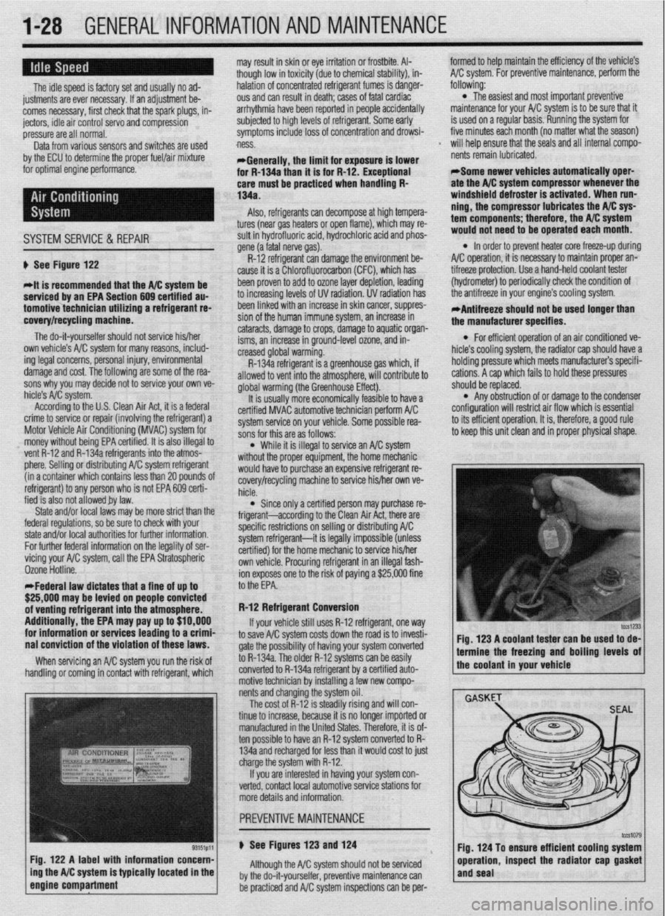
without the proper equipment, the home mechanic ti See Figure 122
*it is recommended that the A/C svstem be
serviced by an EPA Section 609 cehified au-
tomotivetechnicfan utilizing a refrigerant re-
covery/recycling machfne.
The do-it-yourselfer should not service his/her
own vehicle’s A/C system for many reasons, includ-
ing legal concerns, personal injury, environmental
damage and cost. The following are some of the rea-
sons why you may decide not to service your own ve-
hicle’s A/C system.
According to the U.S. Clean Air Act, it is a federal
crime to service or repair (involving the refrigerant) a
Motor Vehicle Air Conditioning (MVAC) system for
money without being EPA certified. It is also illegal to
vent R-12 and R-134a refrigerants into the atmos-
phere. Selling or distributing A/C system refrigerant
(in a container which contains less than 20 pounds oi
refrigerant) to any person who is not EPA 609 certi-
fied is also not allowed by law.
State and/or local laws may be more strict than the
federal regulations, so be sure to check with your
state and/or local authorities for further information.
For further federal information on the legality of ser-
vicing your AK system, call the EPA Stratospheric
Ozone Hotline.
*Federal law dictates that a fine of up to
$25,000 may be levied on people convicted
of venting refrigerant into the atmosphere.
Additionally, the EPA may pay up to $10,000
for information or services leading to a crimf
nai conviction of the violation of these laws.
When servicing an A/C system you run the risk of
handling or coming in contact with refrigerant, which
Fig. 122 A label with information concern-
ing the A/C system is typically located in the
engine compartment
f would haveto purchase an expensive refrigerant re-
covery/recycling machine to service his/her own ve-
hicle.
l Since only a certified person may purchase re-
frigerant-according to the Clean Air Act, there are
specific restrictions on selling or distributing A/C
system refrigerant-it is legally impossible (unless
certified) for the home mechanic to service his/her
own vehicle. Procuring refrigerant in an illegal fash-
ion exposes one to the risk of paying a $25,000 fine
to the EPA.
R-12 Refrigerant Conversion
If your vehicle still uses R-12 refrigerant, one
way to save A/C system costs down the road is to invesh-
gate the possibility of having your system converted
to R-134a. The older R-12 systems can be easily
converted to R-134a refrigerant by a certified auto-
motive technician by installing a few new compo-
nents and changing the system oil.
The cost of R-12 is steadily rising and will con-
tinue to increase, because it is no longer imported or
manufactured in the United States. Therefore, it is of-
ten possible to have an R-12 system converted to R-
134a and recharged for less than it would cost to just
charge the system with R-12.
If you are interested in having your system con-
verted, contact local automotive service stations for
more details and information.
u See Figures 123 and 124
Although the A/C system should not be serviced
by the do-it-yourselfer, preventive maintenance can
be practiced and A/C system inspections can be per- Fig. 123 A coolant tester can be used to de-
1 termine the freezing and boiling levels of
the coolant in your vehicle
Fig. 124 To ensure efficient cooling system
operation, inspect the radiator cap gasket
and seal
Page 46 of 408
GENERAL INFORMATION AND MAINTENANCE 1-47
ramps are also a handy and safe way to both raise l When the drive wheels are to remain on the
and support the vehicle. Be careful though, some ground, leave the vehicle in gear to help prevent it
ramps may be too steep to drive your vehicle onto
The following safety points cannot be overempha- from rolling.
without scraping the front bottom panels. Never sup-
sized:
l Always use jackstands to support the vehicle
port the vehicle on any suspension member (unless l Always block the opposite wheel or wheels to when you are working underneath. Place the stands
specifically instructed to do so by a repair manual) or
keep the vehicle from rolling off the jack. beneath the vehrcle’s jacking brackets Before climb-
by an underbody panel.
l When raising the front of the vehicle, firmly ap- ing underneath, rock the vehicle a bit to make sure it
ply the parking brake. is firmly supported.
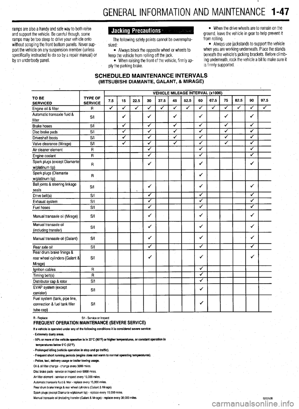
SCHEDULED MAINTENANCE INTERVALS (MITSUBISHI DIAMANTE, GALANT, & MIRAGE)
VEHICLE MILEAGE INTERVAL (x1000)
7.5 15
22.5 30 37.5 45 52.5 60 67.5 75 62.5 90 97.5
J J
J 4 J J 4 4 4 J J
J 4
4
J J J J 4 TO BE
Ball loints &steering linkage
S/I J J J
seals
Dnve belt(s) S/I 4 4 J
Fvha,,rt cvctom $/I
J J J LmI,..“w. “,YL”,‘. Fuel hoses
+
Manual transaxle oil (Galant)
connectlon & fuel tank filler
R. Replace S/I - Sefwce or Inspect FREQUENT OPERATION MAINTENANCE (SEVERE SERVICE) II a vehicle is operated under any of the following conditions it is considered severe service:
- Extremely dusty areas.
- 50% or more of the vehicle operation is in 32% (WF) or higher temperatures, or constant opsralion in
temperatures below 0% (32°F).
- Prolonged idling (vehicle operation in stop and go traffic).
_ Frequent short running periods (engine does not warm to normal operating temfwatures).
- Police, taxi, delivery usage or trailer towing usage.
0118 011 filter change-change every 3CQO miles.
Disc brake pads - sewce or Inspect ever 6COO miles
AN hlter element _ setwe or inspect every 15,000 miles.
Automatic transaxle lluld 8 filter . replace every 15,COO m&s.
Rear drum brake Ikmngs & rear wheel cylinders (Galant & Mirage)
Spark plugs (except Dlamante wlplabnum tip) - replace every 15,COO miles.
Manual transaxle 011 (mcludlng transfer (Galant & Mirage). replace every 30,000 miles.