2024 FORD F650/750 reset
[x] Cancel search: resetPage 148 of 386
Vehicles with Automatic Transmission
When you switch the ignition on, thesystem automatically turns on. You cannotturn the system on or off.
AIR BRAKES
WARNING: Failure to maintainproper air brake adjustment can resultin reduction or loss of braking ability.
WARNING: Do not drive or continueto drive if the low air pressure buzzer issounding or the brake warning light is lit.These warnings indicate that air pressureis not to normal operating level.Continued use of the vehicle could resultin loss of braking ability.
WARNING: Avoid repeated lightapplication of the brake pedal. Thisdepletes air pressure faster and couldresult in loss of braking capability.
WARNING: Do not move thevehicle when the air pressure isinsufficient because the brake systemmay be inoperative.
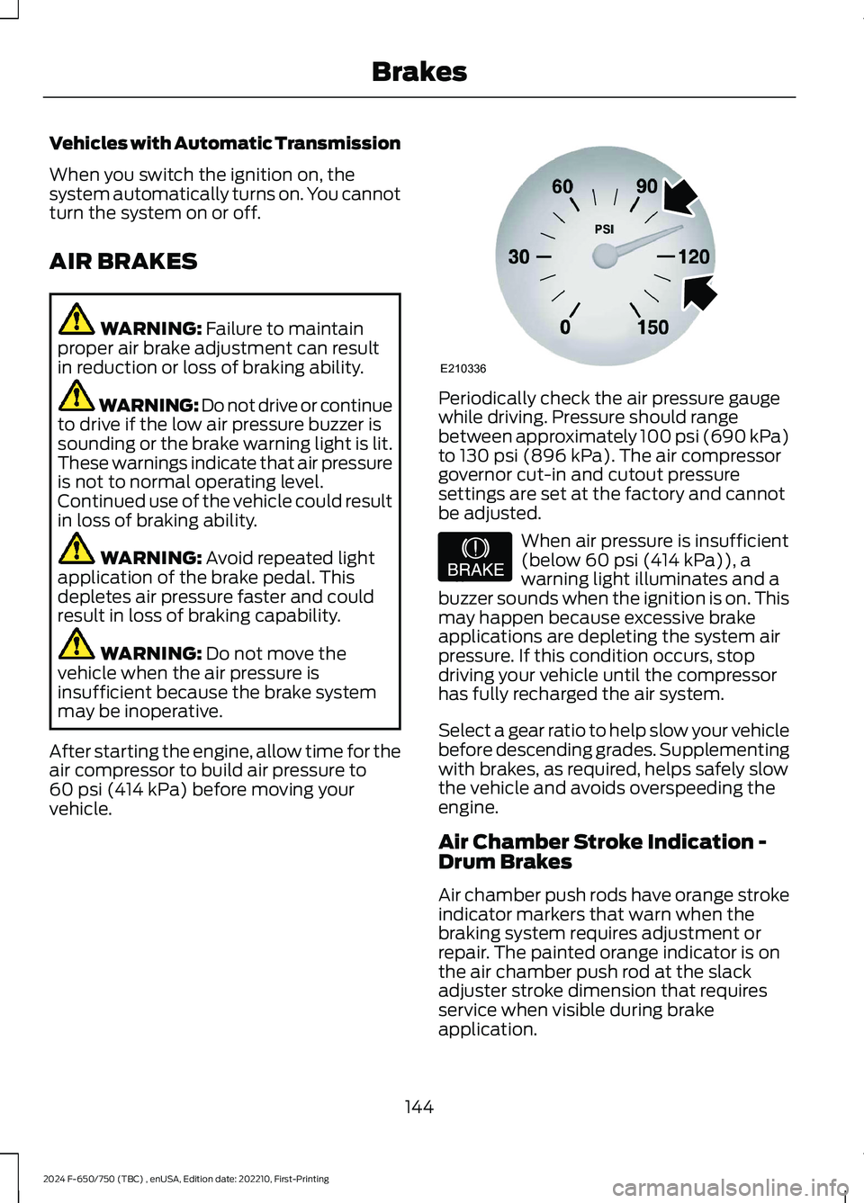
After starting the engine, allow time for theair compressor to build air pressure to60 psi (414 kPa) before moving yourvehicle.
Periodically check the air pressure gaugewhile driving. Pressure should rangebetween approximately 100 psi (690 kPa)to 130 psi (896 kPa). The air compressorgovernor cut-in and cutout pressuresettings are set at the factory and cannotbe adjusted.
When air pressure is insufficient(below 60 psi (414 kPa)), awarning light illuminates and abuzzer sounds when the ignition is on. Thismay happen because excessive brakeapplications are depleting the system airpressure. If this condition occurs, stopdriving your vehicle until the compressorhas fully recharged the air system.
Select a gear ratio to help slow your vehiclebefore descending grades. Supplementingwith brakes, as required, helps safely slowthe vehicle and avoids overspeeding theengine.
Air Chamber Stroke Indication -Drum Brakes
Air chamber push rods have orange strokeindicator markers that warn when thebraking system requires adjustment orrepair. The painted orange indicator is onthe air chamber push rod at the slackadjuster stroke dimension that requiresservice when visible during brakeapplication.
144
2024 F-650/750 (TBC) , enUSA, Edition date: 202210, First-PrintingBrakesE210336 E206772
Page 165 of 386
Following a Vehicle
WARNING: When following avehicle that is braking, your vehicle doesnot always decelerate quickly enough toavoid a crash without driver intervention.Apply the brakes when necessary. Failureto follow this instruction could result inpersonal injury or death.
WARNING: The system only warnsof vehicles detected by the radar sensor.In some cases there may be no warningor a delayed warning. Apply the brakeswhen necessary. Failure to follow thisinstruction could result in personal injuryor death.
Note:When you are following a vehicle andyou switch on a direction indicator, adaptivecruise control may provide a smalltemporary acceleration to help you pass.
Note:The brakes may emit noise whenapplied by the system.
When a vehicle ahead of you enters thesame lane or a slower vehicle is ahead inthe same lane, the vehicle speed adjuststo maintain a preset gap distance. Avehicle graphic illuminates in theinstrument cluster.
Your vehicle maintains a consistent gapfrom the vehicle ahead until any of thefollowing occur:
•The vehicle in front of you acceleratesto a speed above the set speed.
•The vehicle in front of you moves outof the lane you are in.
•Your vehicle speed falls below 12 mph(20 km/h).
•You set a new gap distance.
The system applies the brakes to slow yourvehicle to maintain a safe gap distancefrom the vehicle in front. The system onlyapplies limited braking. You can overridethe system by applying the brakes.
If the system determines that its maximumbraking level is not sufficient, an audiblewarning sounds, a message appears in theinformation display and an indicatorflashes when the system continues tobrake. Take immediate action.
Setting the Gap Distance
You can decrease or increase the distancebetween your vehicle and the vehicle infront by pressing the gap control.
Press and release to decreasethe gap distance.
Press and release to increase thegap distance.
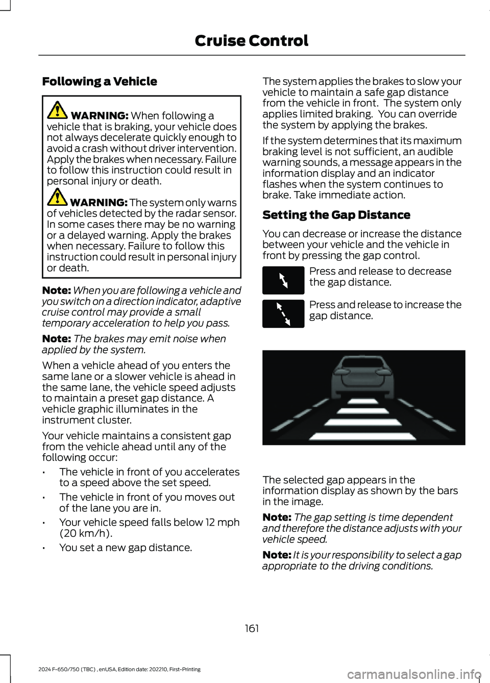
The selected gap appears in theinformation display as shown by the barsin the image.
Note:The gap setting is time dependentand therefore the distance adjusts with yourvehicle speed.
Note:It is your responsibility to select a gapappropriate to the driving conditions.
161
2024 F-650/750 (TBC) , enUSA, Edition date: 202210, First-PrintingCruise ControlE263697 E263696 E233874
Page 171 of 386
The warning system uses two stages. Atfirst the system issues a temporary warningthat you need to take a rest. This messageonly appears for a short time. If the systemdetects further reduction in drivingalertness, another warning could be issuedwhich remains in the information displayfor a longer time. Press OK on the steeringwheel control to clear the warning. Whenactive the system runs in the backgroundand only issues a warning if required.
Resetting the System
You can reset the system by either:
•Switching the ignition off and on.
•Stopping the vehicle and then openingand closing the driver door.
LANE KEEPING SYSTEM (IF
EQUIPPED)
WARNING: You are responsible forcontrolling your vehicle at all times. Thesystem is designed to be an aid and doesnot relieve you of your responsibility todrive with due care and attention. Failureto follow this instruction could result inthe loss of control of your vehicle,personal injury or death.
WARNING: Always drive with duecare and attention when using andoperating the controls and features onyour vehicle.
WARNING: In cold and severeweather conditions the system may notfunction. Rain, snow and spray can alllimit sensor performance.
WARNING: The system will notoperate if the sensor cannot track theroad lane markings.
WARNING: The sensor mayincorrectly track lane markings as otherstructures or objects. This can result ina false or missed warning.
WARNING: Large contrasts inoutside lighting can limit sensorperformance.
WARNING: The system may notoperate properly if the sensor is blocked.Keep the windshield free fromobstruction.
WARNING: If damage occurs in theimmediate area surrounding the sensor,have your vehicle checked as soon aspossible.
WARNING: The system may notcorrectly operate if your vehicle is fittedwith a suspension kit not approved byus.
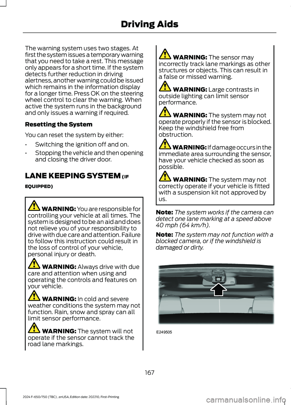
Note:The system works if the camera candetect one lane marking at a speed above40 mph (64 km/h).
Note:The system may not function with ablocked camera, or if the windshield isdamaged or dirty.
167
2024 F-650/750 (TBC) , enUSA, Edition date: 202210, First-PrintingDriving AidsE249505
Page 206 of 386

FUSE SPECIFICATION CHART
Engine Compartment Fuse Box
WARNING: Always disconnect thebattery before servicing high currentfuses.
WARNING: To reduce risk ofelectrical shock, always replace thecover to the power distribution boxbefore reconnecting the battery orrefilling fluid reservoirs.
The engine compartment fuse box is in theengine compartment. It has high-currentfuses that protect your vehicle's mainelectrical systems from overloads.
If you disconnect and reconnect thebattery, you need to reset some features.See Changing the 12V Battery (page 246).
Replace fuses with the same type andrating. See Changing a Fuse (page 211).
Protected ComponentRatingItem
Horn.20 A1
Blower motor.40 A2
202
2024 F-650/750 (TBC) , enUSA, Edition date: 202210, First-PrintingFusesE251921
Page 232 of 386

Do not use supplemental engine oiladditives because they are unnecessaryand could lead to engine damage that thevehicle warranty may not cover.
1.Clean the area surrounding the engineoil filler cap before you remove it.
2.Remove the engine oil filler cap.
3.Add engine oil that meets ourspecifications. See Capacities andSpecifications (page 291).
4.Reinstall the engine oil filler cap. Turnit clockwise until you feel a strongresistance.
Note: Do not add oil further than themaximum mark. Oil levels above themaximum mark may cause engine damage.
Note:Immediately soak up any oil spillagewith an absorbent cloth.
Engine Oil Pressure Warning Lamp
WARNING: If it illuminates whenyou are driving do not continue yourjourney, even if the oil level is correct.Have your vehicle checked.
It illuminates when you switchthe ignition on.
If it illuminates when the engineis running this indicates a malfunction.Stop your vehicle as soon as it is safe todo so and switch the engine off. Check theengine oil level. If the oil level is sufficient,this indicates a system malfunction. Haveyour vehicle checked as soon as possible.
CHANGING THE ENGINE OIL
AND OIL FILTER
WARNING: Do not add engine oilwhen the engine is hot. Failure to followthis instruction could result in personalinjury.
Your vehicle has an Intelligent Oil LifeMonitor™ that calculates the proper oilchange service interval. When theinformation display indicates: OIL CHANGEREQUIRED, change the engine oil and oilfilter. See Information Displays (page71).
The engine oil filter protects your engineby filtering harmful, abrasive or sludgeparticles and particles significantly smallerthan most available will-fit filters. SeeMotorcraft Parts (page 293).
1.Unscrew the oil filter and oil pan drainplug and wait for the oil to drain.
2.Replace the filter.
3.Reinstall the oil pan drain plug.
4.Refill the engine with new oil. SeeEngine Oil Capacity andSpecification (page 299).
5.Reset the Intelligent Oil Life Monitor™.See Information Displays (page 71).
Engine Lubrication for SevereService Operation
The following conditions define severeoperation:
•Frequent or extended idling such asover 10 minutes per hour of normaldriving.
•Low-speed operation or stationary use.
•If the vehicle is operated in sustained,ambient temperatures below -9°F(-23°C) or above 100°F (38°C).
228
2024 F-650/750 (TBC) , enUSA, Edition date: 202210, First-PrintingMaintenanceE67022
Page 233 of 386
•Frequent low-speed operation, orconsistent heavy traffic less than25 mph (40 km/h).
•Operating in severe dust conditions.
•Operating the vehicle off road.
•Towing a trailer over 1,000 mi(1,600 km).
•Sustained, high-speed driving at thegross vehicle weight rating.
•Use of fuels with sulfur content otherthan ultra-low sulfur diesel (ULSD).
•Use of high-sulfur diesel fuel.
Only use engine oil that meets ourspecifications. See Capacities andSpecifications (page 291).
OIL CHANGE INDICATOR
RESET
Base Cluster
Use the information display controls onthe steering wheel to reset the oil changeindicator.
From the main menu scroll to:
Action and DescriptionMessage
Press the right arrow button,then from this menu scrollto the following message.
Settings
Press the down arrowbutton, then from this menuscroll to the followingmessage.
Vehicle
Press the right arrow button,then from this menu scrollto the following message.
Oil LifeReset
Press and hold the OKbutton until the instrumentcluster displays thefollowing message.
Oil LifeHold toReset
Action and DescriptionMessage
Press and hold the OKbutton until the instrumentcluster displays thefollowing message.
Oil LifeHold OKto Reset
Reset Complete
If the instrument clusterdisplays the followingmessage, repeat theprocess.
Reset Cancelled
High Series Cluster
Use the information display controls onthe steering wheel to reset the oil changeindicator.
From the main menu scroll to:
Action and DescriptionMessage
Press the down arrowbutton, then from this menuscroll to the followingmessage.
Truck Info
Press the OK button.Mainten-anceMonitor
Press the down arrowbutton, then from this menuscroll to the followingmessage.
Oil Life:xxx%
Press the OK button.Oil Life
Press and hold the OKbutton until the instrumentcluster displays thefollowing message.
Oil LifeHold OK toReset
229
2024 F-650/750 (TBC) , enUSA, Edition date: 202210, First-PrintingMaintenance
Page 234 of 386
Action and DescriptionMessage
Oil Life: 100%
When the oil change indic-ator resets, the instrumentcluster displays 100%.
Repeat the process if the oilchange indicator does notreset.
CHANGING THE ENGINE AIR
FILTER - 6.7L DIESEL
Air Filter Restriction Gauge
WARNING: To reduce the risk ofvehicle damage and personal burninjuries, do not start your engine with theair cleaner removed and do not removeit while the engine is running.
Note:Operating your vehicle in heavysnowfall or extreme rain conditions mayallow excessive amounts of snow or waterinto the air intake system. This could plugor soak the air filter and cause the engine tolose power or shut down.
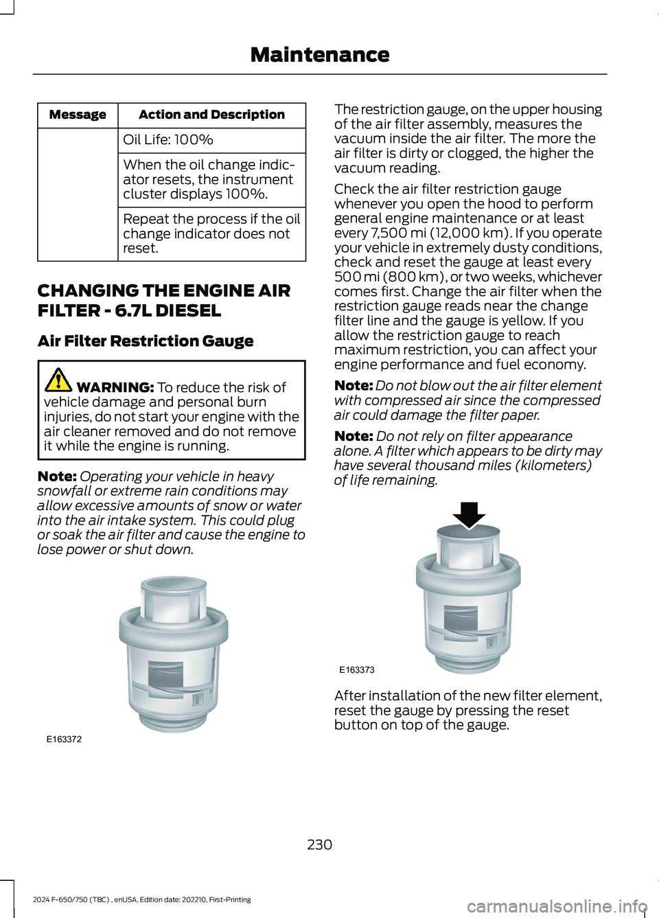
The restriction gauge, on the upper housingof the air filter assembly, measures thevacuum inside the air filter. The more theair filter is dirty or clogged, the higher thevacuum reading.
Check the air filter restriction gaugewhenever you open the hood to performgeneral engine maintenance or at leastevery 7,500 mi (12,000 km). If you operateyour vehicle in extremely dusty conditions,check and reset the gauge at least every500 mi (800 km), or two weeks, whichevercomes first. Change the air filter when therestriction gauge reads near the changefilter line and the gauge is yellow. If youallow the restriction gauge to reachmaximum restriction, you can affect yourengine performance and fuel economy.
Note:Do not blow out the air filter elementwith compressed air since the compressedair could damage the filter paper.
Note:Do not rely on filter appearancealone. A filter which appears to be dirty mayhave several thousand miles (kilometers)of life remaining.
After installation of the new filter element,reset the gauge by pressing the resetbutton on top of the gauge.
230
2024 F-650/750 (TBC) , enUSA, Edition date: 202210, First-PrintingMaintenanceE163372 E163373
Page 235 of 386
We recommend the following actions afteroperating the vehicle up to 200 mi(320 km) in heavy snowfall or extremerain:
•Snow: At the earliest opportunity, openthe hood and clear all the snow and icefrom the air filter housing inlet. Do NOTremove the foam filter and reset theair filter restriction gauge.
•Extreme rain: The air filter dries afterabout 15–30 minutes at highwayspeeds. At the earliest opportunity,open the hood and reset the air filterrestriction gauge.
Air Filter Replacement
When replacing the air filter element, usea Motorcraft® air filter element. SeeMotorcraft Parts (page 293).
Note:Failure to use the correct air filterelement may result in severe enginedamage.
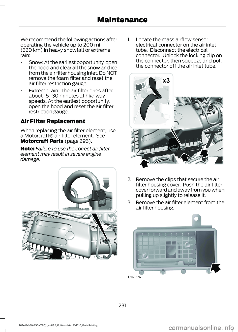
1.Locate the mass airflow sensorelectrical connector on the air inlettube. Disconnect the electricalconnector. Unlock the locking clip onthe connector, then squeeze and pullthe connector off the air inlet tube.
2.Remove the clips that secure the airfilter housing cover. Push the air filtercover forward and away from you whenpulling up slightly to release it.
3.Remove the air filter element from theair filter housing.
231
2024 F-650/750 (TBC) , enUSA, Edition date: 202210, First-PrintingMaintenanceE317651 x3E317652 E163376