2024 FORD F650/750 instrument panel
[x] Cancel search: instrument panelPage 100 of 386

12 Volt DC Power Point
WARNING: Do not plug optionalelectrical accessories into the cigarlighter socket. Incorrect use of the cigarlighter can cause damage not coveredby the vehicle warranty, and can resultin fire or serious injury.
Note:When you switch the ignition on, youcan use the socket to power 12 voltappliances with a maximum current ratingof 15 amps.
If the power supply does not work after youswitch the ignition off, switch the ignitionon.Note:Do not hang any accessory from theaccessory plug.
Note:Do not use the power point over thevehicle capacity of 12 volt DC 180 watts ora fuse may blow.
Note:Always keep the power point capsclosed when not in use.
Do not insert objects other than anaccessory plug into the power point. Thisdamages the power point and may blowthe fuse.
Run the vehicle for full capacity use of thepower point.
To prevent the battery from running out ofcharge:
•Do not use the power point longer thannecessary when the vehicle is notrunning.
•Do not leave devices plugged inovernight or when you park your vehiclefor extended periods.
Locations
Power points may be in the followinglocations:
•On the instrument panel (twolocations).
•Inside the front under-seat storagecompartment.
•Inside the rear under-seat storagecompartment.
110 Volt AC Power Point (If Equipped)
WARNING: Do not keep electricaldevices plugged in the power pointwhenever the device is not in use. Do notuse any extension cord with the 110 voltAC power point, since it will defeat thesafety protection design. Doing so maycause the power point to overload dueto powering multiple devices that canreach beyond the 150 watt load limit andcould result in fire or serious injury.
Note:The power point turns off when youswitch the ignition off, or when the batteryvoltage drops below 11 volts.
You can use the power point for electricdevices that require up to 150 watts. It isin the center of the instrument panel.
Note:Depending on your vehicle, the powerpoint cover may open to the right or upward.
96
2024 F-650/750 (TBC) , enUSA, Edition date: 202210, First-PrintingAuxiliary Power PointsE193395
Page 102 of 386
LOCATING THE USB PORTS
Data Transfer USB Ports
The USB ports could be in the followinglocations:
•On the lower instrument panel.
•Inside the center console.
Note: These USB ports can also chargedevices.
Note: Not all USB ports in your vehicle havedata transfer capabilities.
Note: We recommend using only USB-IFcertified cables and adapters. Non-certifiedcables and adapters may not work.
Charge Only USB Ports
The USB ports could be in the followinglocations:
•On the lower instrument panel.
•On the upper instrument panel.
•Inside the media bin.
•Inside the center console.
•On the rear of the center console.
•Behind the first row seats.
•In the cargo area.
PLAYING MEDIA USING THE
USB PORT
WARNING: Driving while distractedcan result in loss of vehicle control, crashand injury. We strongly recommend thatyou use extreme caution when using anydevice that may take your focus off theroad. Your primary responsibility is thesafe operation of your vehicle. Werecommend against the use of anyhand-held device while driving andencourage the use of voice-operatedsystems when possible. Make sure youare aware of all applicable local lawsthat may affect the use of electronicdevices while driving.
Connect your device to a data transfer USBport.
Press the audio button on thefeature bar.
Select Sources.
Select the USB option.
Press to play a track. Press againto pause the track.
Press to skip to the next track.
Press and hold to fast forwardthrough the track.
Press once to return to thebeginning of a track. Repeatedlypress to return to previoustracks.
Press and hold to fast rewind.
CHARGING A DEVICE
Connect your device to the USB port.
98
2024 F-650/750 (TBC) , enUSA, Edition date: 202210, First-PrintingUSB PortsE250655 E263583 E100027
Page 120 of 386
Keep a record for at least one month andrecord the type of driving (city or highway).This provides an accurate estimate of yourvehicle's fuel economy under currentdriving conditions. Keeping records duringsummer and winter will show howtemperature impacts fuel economy.
Conditions
•Heavily loading your vehicle reducesfuel economy.
•Carrying unnecessary weight in yourvehicle may reduce fuel economy.
•Adding certain accessories to yourvehicle such as bug deflectors, rollbarsor light bars, running boards and skiracks may reduce fuel economy.
•Using fuel blended with alcohol maylower fuel economy.
•Fuel economy may decrease with lowertemperatures.
•Fuel economy may decrease whendriving short distances.
•You will get better fuel economy whendriving on flat terrain than when drivingon hilly terrain.
FUEL TANK SELECTOR
SWITCH (IF EQUIPPED)
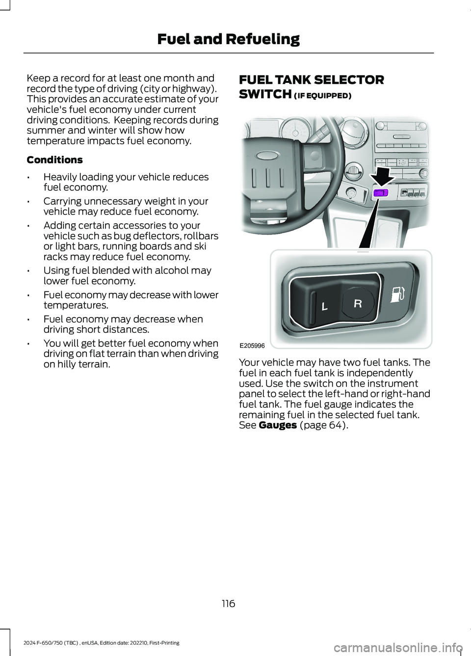
Your vehicle may have two fuel tanks. Thefuel in each fuel tank is independentlyused. Use the switch on the instrumentpanel to select the left-hand or right-handfuel tank. The fuel gauge indicates theremaining fuel in the selected fuel tank.See Gauges (page 64).
116
2024 F-650/750 (TBC) , enUSA, Edition date: 202210, First-PrintingFuel and RefuelingE205996
Page 150 of 386
Note:Installing an exhaust or auxiliarybrake does not necessarily protect theengine from exceeding the maximumgoverned speed. Use the primary brakes tomake sure the engine never exceeds themaximum governed speed under anycircumstance.
Note:Engine speed has a major influenceon limiting performance. When enginespeed stays at the maximum allowablelevel, the exhaust brake operates at peakperformance.
Note:Exhaust brakes operate effectivelywith automatic transmissions. However,performance varies with engine speed andthe gear selected by the transmission.
An exhaust brake is an auxiliary brakingsystem that assists, but does not replace,the primary brake system. It helps controlvehicle speed. It is not a vehicle-stoppingdevice.
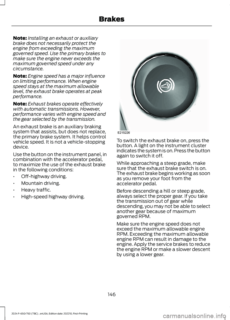
Use the button on the instrument panel, incombination with the accelerator pedal,to maximize the use of the exhaust brakein the following conditions:
•Off-highway driving.
•Mountain driving.
•Heavy traffic.
•High-speed highway driving.
To switch the exhaust brake on, press thebutton. A light on the instrument clusterindicates the system is on. Press the buttonagain to switch it off.
While approaching a steep grade, makesure that the exhaust brake switch is on.The exhaust brake begins working as soonas you remove your foot from theaccelerator pedal.
Before descending a hill or steep grade,always select the proper gear. If you takethe transmission out of gear whiledescending, you may not be able to selectanother gear because of maximumgoverned RPM.
Make sure the engine speed does notexceed the maximum allowable engineRPM. Exceeding the maximum allowableengine RPM can result in damage to theengine. Apply the service brakes to reducethe engine RPM or make a slower descentby using a lower gear.
146
2024 F-650/750 (TBC) , enUSA, Edition date: 202210, First-PrintingBrakesE215226
Page 151 of 386
While driving down a grade, use a lowenough gear to descend safely with aminimum application of the service brakes.As a general guideline, use the same gearas you use to ascend the hill.
Exhaust Brake OperatingCharacteristics
The exhaust brake switches on when youremove your feet from the acceleratorpedal and the exhaust brake is on.
If the brake is working properly, you maynotice:
•A slight change in engine sound whenthe exhaust brake turns on.
•A smooth braking effect. Do not expecta retarding effect similar to sudden,hard application of the service brakes.
•A retarding force possibly felt actingagainst your body during brakeapplication, depending on the gradeand vehicle load. This force helps yourvehicle resist increasing speeds downgrades.
•Engine temperatures remaining in thenormal operating range.
•A drop in engine RPM, depending ongrade and vehicle load, during adescent.
•A decrease in road speed whenapplying the exhaust brake during adescent, except when your vehicle iscarrying a heavy load or the grade isextremely steep. In these instances,you may need to apply the servicebrakes occasionally.
TRAILER BRAKES (IF EQUIPPED)
Trailer Brake Hand Control (If Equipped)
WARNING: The hand controlshould never be used to apply the brakeswhen the tractor and trailer are parkedunattended. Air may leak from thesystem and the vehicle could possiblymove, resulting in possible propertydamage, personal injury or death.
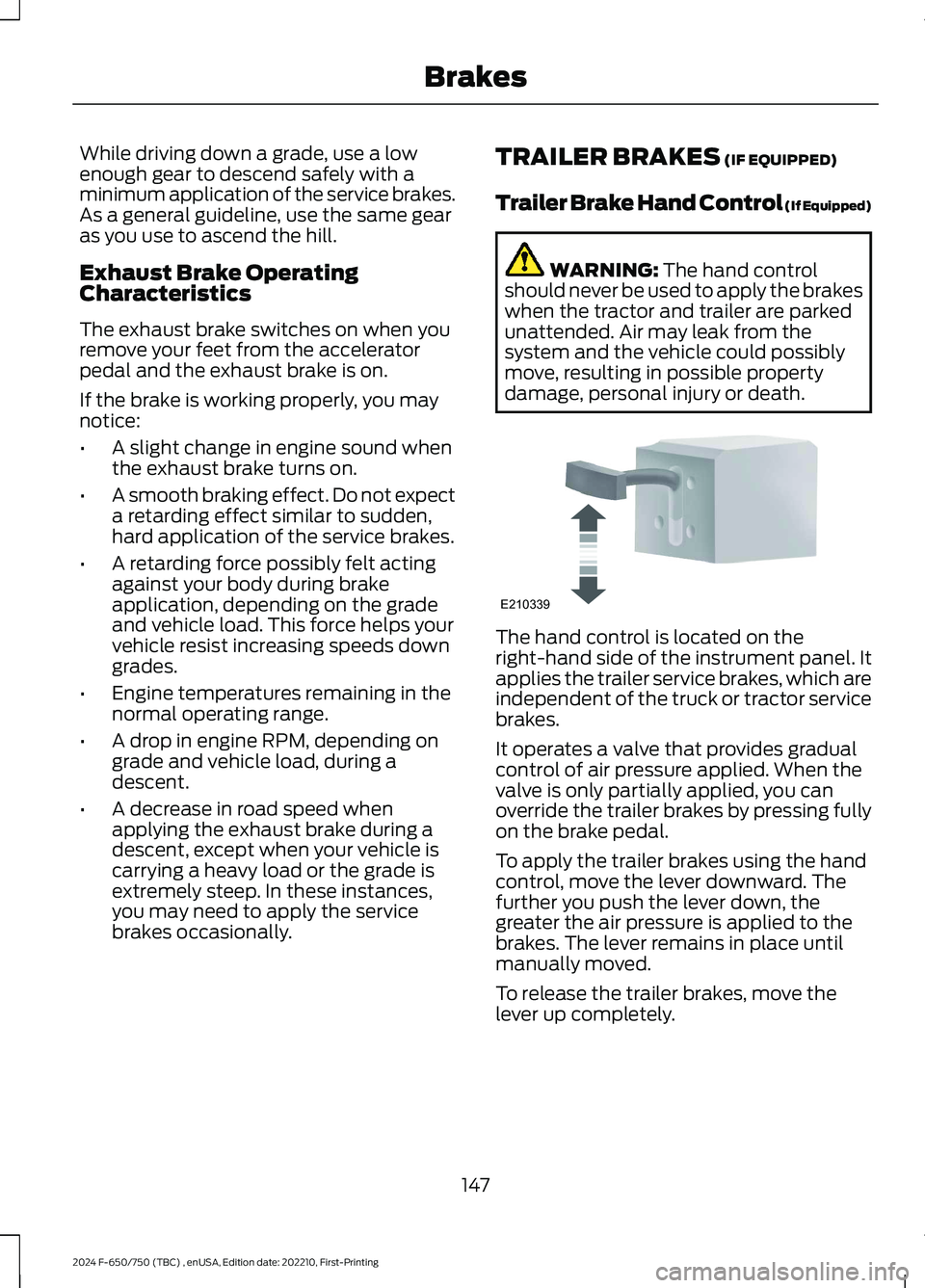
The hand control is located on theright-hand side of the instrument panel. Itapplies the trailer service brakes, which areindependent of the truck or tractor servicebrakes.
It operates a valve that provides gradualcontrol of air pressure applied. When thevalve is only partially applied, you canoverride the trailer brakes by pressing fullyon the brake pedal.
To apply the trailer brakes using the handcontrol, move the lever downward. Thefurther you push the lever down, thegreater the air pressure is applied to thebrakes. The lever remains in place untilmanually moved.
To release the trailer brakes, move thelever up completely.
147
2024 F-650/750 (TBC) , enUSA, Edition date: 202210, First-PrintingBrakesE210339
Page 155 of 386
PRINCIPLE OF OPERATION
The traction control system helps avoiddrive wheel spin and loss of traction.
If your vehicle begins to slide, the systemapplies the brakes to individual wheelsand, when needed, reduces engine powerat the same time. If the wheels spin whenaccelerating on slippery or loose surfaces,the system reduces engine power in orderto increase traction.
USING TRACTION CONTROL -
VEHICLES WITH: AIR BRAKES
WARNING: Operating your vehiclewith the traction control disabled couldlead to an increased risk of loss of vehiclecontrol, vehicle rollover, personal injuryand death.
Press the TCS Off button on theinstrument panel to enable themud/snow mode.
This is beneficial when your vehicle is stuckin snow or on a slippery road surface. Thismode allows wheel spin to dig your vehicleout and allows you to rock your vehicle.
Press the switch again to select standardtraction control. The system automaticallyselects standard traction control at thenext ignition cycle.
System Indicator Light
Note:If the traction control light does notflash during a traction control event or staysilluminated, the system is not functioningproperly. Take your vehicle to an authorizeddealer for service.
During traction control operation, thetraction control light flashes rapidly andthe engine does not rev-up when you pressfurther on the accelerator. This is normaland is no reason for concern.
In mud/snow mode, the TCS OFF lightilluminates on the instrument cluster. If atraction event occurs in either mode, thestability and traction control light flashesrapidly.
USING TRACTION CONTROL -
VEHICLES WITH: HYDRAULIC
BRAKES
WARNING: Operating your vehiclewith the traction control disabled couldlead to an increased risk of loss of vehiclecontrol, vehicle rollover, personal injuryand death.
The system turns on each time you switchthe ignition on.
Use the traction control buttonon the instrument panel toswitch the system off or on.
If your vehicle is stuck in mud or snow,switching traction control off is beneficialas this allows the wheels to spin.
Press the button again to switch thetraction control system on.
System Indicator Light
Note:If the traction control light does notflash during a traction control event or stayson, the system is not operating. Have thesystem checked as soon as possible.
During a traction control event, the tractioncontrol light rapidly flashes. Pressingfurther on the accelerator does not causethe engine to rev higher. This is normal andis no reason for concern.
151
2024 F-650/750 (TBC) , enUSA, Edition date: 202210, First-PrintingTraction ControlE330660 E330660
Page 183 of 386
AIR SUSPENSION
Note:Do not operate your vehicle withoutair in the suspension springs. Operating yourvehicle without air in the suspension springsdamages the suspension, degrades rideperformance and may cause propertydamage.
The air suspension system automaticallyadjusts to different loads to maintain aconstant frame height, allows for ease ofvehicle loading, provides improved vehicleride, and increased driver comfort.
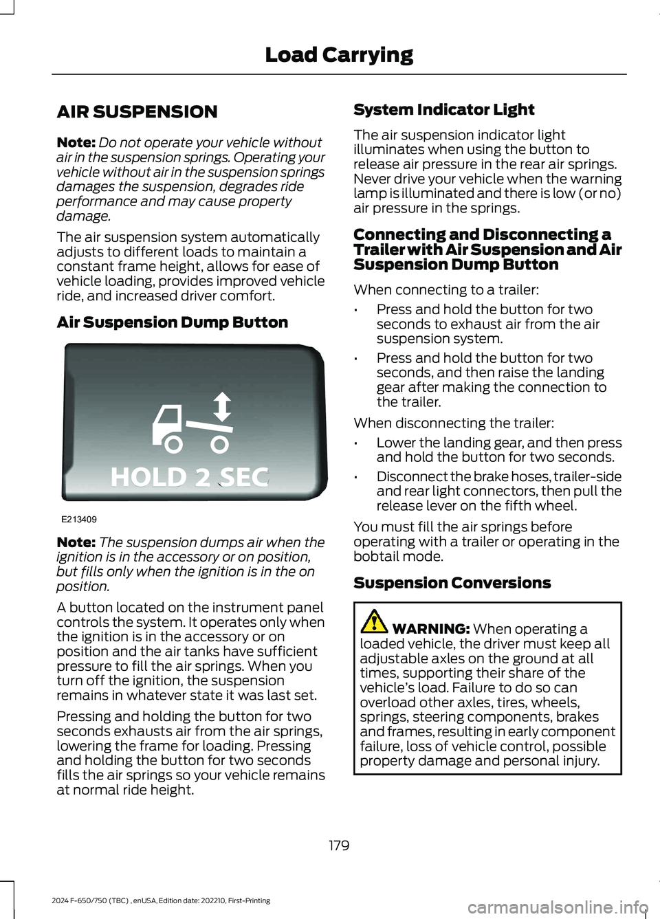
Air Suspension Dump Button
Note:The suspension dumps air when theignition is in the accessory or on position,but fills only when the ignition is in the onposition.
A button located on the instrument panelcontrols the system. It operates only whenthe ignition is in the accessory or onposition and the air tanks have sufficientpressure to fill the air springs. When youturn off the ignition, the suspensionremains in whatever state it was last set.
Pressing and holding the button for twoseconds exhausts air from the air springs,lowering the frame for loading. Pressingand holding the button for two secondsfills the air springs so your vehicle remainsat normal ride height.
System Indicator Light
The air suspension indicator lightilluminates when using the button torelease air pressure in the rear air springs.Never drive your vehicle when the warninglamp is illuminated and there is low (or no)air pressure in the springs.
Connecting and Disconnecting aTrailer with Air Suspension and AirSuspension Dump Button
When connecting to a trailer:
•Press and hold the button for twoseconds to exhaust air from the airsuspension system.
•Press and hold the button for twoseconds, and then raise the landinggear after making the connection tothe trailer.
When disconnecting the trailer:
•Lower the landing gear, and then pressand hold the button for two seconds.
•Disconnect the brake hoses, trailer-sideand rear light connectors, then pull therelease lever on the fifth wheel.
You must fill the air springs beforeoperating with a trailer or operating in thebobtail mode.
Suspension Conversions
WARNING: When operating aloaded vehicle, the driver must keep alladjustable axles on the ground at alltimes, supporting their share of thevehicle’s load. Failure to do so canoverload other axles, tires, wheels,springs, steering components, brakesand frames, resulting in early componentfailure, loss of vehicle control, possibleproperty damage and personal injury.
179
2024 F-650/750 (TBC) , enUSA, Edition date: 202210, First-PrintingLoad CarryingE213409
Page 194 of 386
HAZARD FLASHERS
Note:If used when the vehicle is notrunning, the battery loses charge. As a result,there may be insufficient power to restartyour vehicle.
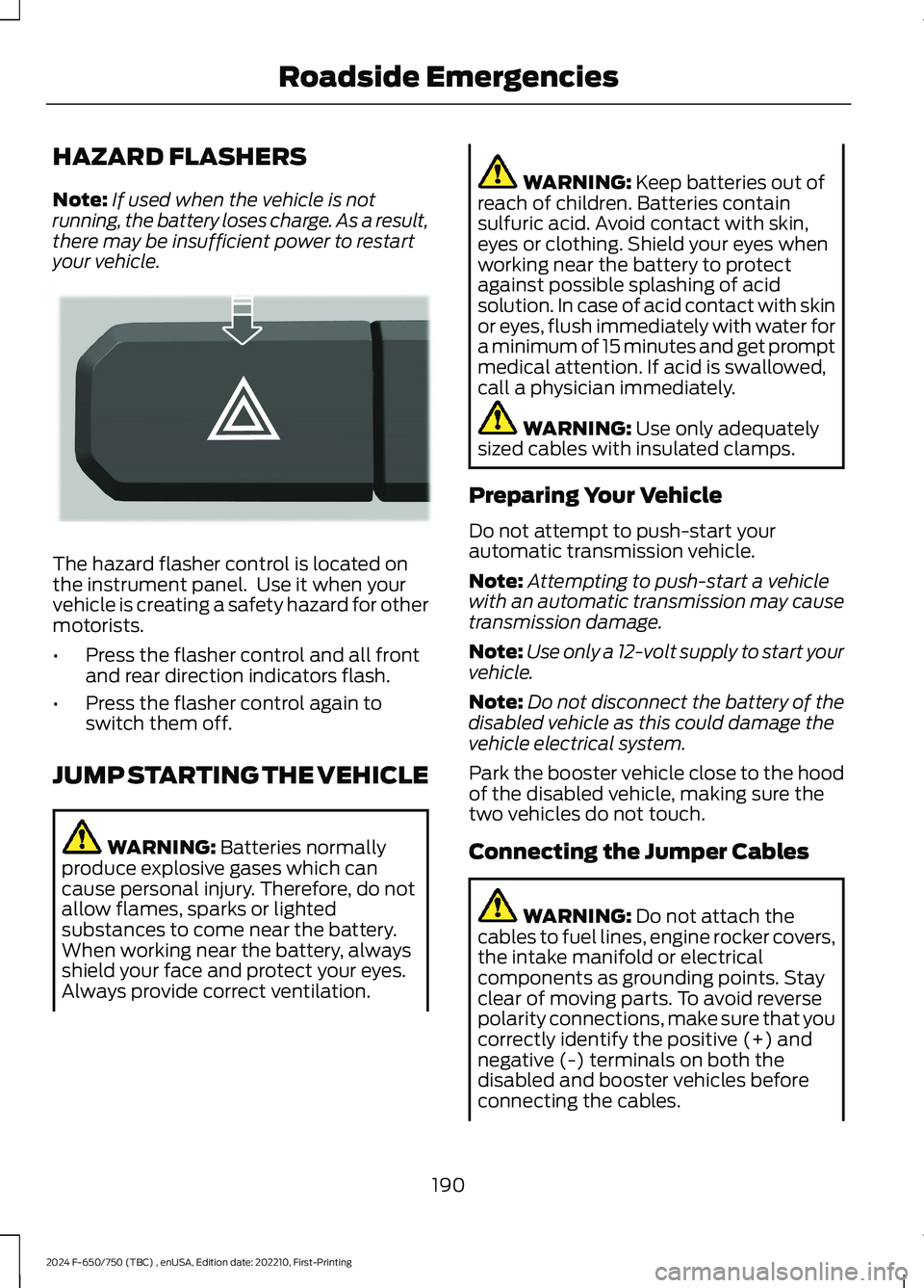
The hazard flasher control is located onthe instrument panel. Use it when yourvehicle is creating a safety hazard for othermotorists.
•Press the flasher control and all frontand rear direction indicators flash.
•Press the flasher control again toswitch them off.
JUMP STARTING THE VEHICLE
WARNING: Batteries normallyproduce explosive gases which cancause personal injury. Therefore, do notallow flames, sparks or lightedsubstances to come near the battery.When working near the battery, alwaysshield your face and protect your eyes.Always provide correct ventilation.
WARNING: Keep batteries out ofreach of children. Batteries containsulfuric acid. Avoid contact with skin,eyes or clothing. Shield your eyes whenworking near the battery to protectagainst possible splashing of acidsolution. In case of acid contact with skinor eyes, flush immediately with water fora minimum of 15 minutes and get promptmedical attention. If acid is swallowed,call a physician immediately.
WARNING: Use only adequatelysized cables with insulated clamps.
Preparing Your Vehicle
Do not attempt to push-start yourautomatic transmission vehicle.
Note:Attempting to push-start a vehiclewith an automatic transmission may causetransmission damage.
Note:Use only a 12-volt supply to start yourvehicle.
Note:Do not disconnect the battery of thedisabled vehicle as this could damage thevehicle electrical system.
Park the booster vehicle close to the hoodof the disabled vehicle, making sure thetwo vehicles do not touch.
Connecting the Jumper Cables
WARNING: Do not attach thecables to fuel lines, engine rocker covers,the intake manifold or electricalcomponents as grounding points. Stayclear of moving parts. To avoid reversepolarity connections, make sure that youcorrectly identify the positive (+) andnegative (-) terminals on both thedisabled and booster vehicles beforeconnecting the cables.
190
2024 F-650/750 (TBC) , enUSA, Edition date: 202210, First-PrintingRoadside EmergenciesE304635