2024 FORD F650/750 charging
[x] Cancel search: chargingPage 6 of 386

Automatic High Beam Control.................57
Direction Indicators......................................58
Interior Lamps................................................58
Windows and Mirrors
Power Windows............................................60
Exterior Mirrors................................................61
Interior Mirror..................................................63
Sun Visors........................................................63
Instrument Cluster
Gauges..............................................................64
Warning Lamps and Indicators................67
Audible Warnings and Indicators............70
Information Displays
General Information......................................71
Information Messages.................................75
Climate Control
Manual Climate Control.............................86
Hints on Controlling the Interior Climate...........................................................................87
Heated Exterior Mirrors...............................88
Seats
Sitting in the Correct Position..................89
Head Restraints.............................................89
Manual Seats...................................................91
Power Seats....................................................92
Rear Seats.......................................................94
Front Seat Armrest.......................................95
Rear Seat Armrest........................................95
Auxiliary Power Points
Auxiliary Power Points................................96
USB Ports
Locating the USB Ports..............................98
Playing Media Using the USB Port.........98
Charging a Device.........................................98
Storage Compartments
Overhead Console......................................100
Starting and Stopping theEngine
General Information....................................101
Ignition Switch...............................................101
Starting a Gasoline Engine......................102
Starting a Diesel Engine............................103
Switching Off the Engine.........................104
Engine Idle Shutdown...............................105
Engine Block Heater...................................105
Fuel and Refueling
Safety Precautions......................................107
Fuel Quality - Diesel...................................108
Fuel Quality - Gasoline................................111
Running Out of Fuel - Diesel.....................112
Running Out of Fuel - Gasoline...............112
Refueling - Diesel..........................................112
Refueling - Gasoline....................................114
Fuel Consumption........................................115
Fuel Tank Selector Switch........................116
Engine Emission Control
Emission Law..................................................117
Catalytic Converter......................................118
Selective Catalytic Reductant System -Diesel...........................................................120
Diesel Particulate Filter.............................124
Transmission
Automatic Transmission..........................130
Power Take-Off............................................135
Rear Axle
General Information...................................136
2
2024 F-650/750 (TBC) , enUSA, Edition date: 202210, First-PrintingTable of Contents
Page 81 of 386
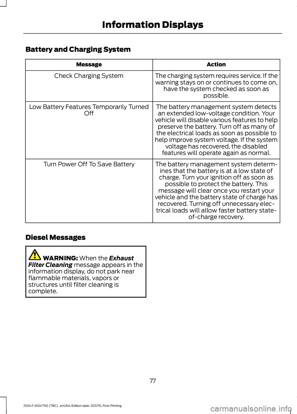
Battery and Charging System
ActionMessage
The charging system requires service. If thewarning stays on or continues to come on,have the system checked as soon aspossible.
Check Charging System
The battery management system detectsan extended low-voltage condition. Yourvehicle will disable various features to helppreserve the battery. Turn off as many ofthe electrical loads as soon as possible tohelp improve system voltage. If the systemvoltage has recovered, the disabledfeatures will operate again as normal.
Low Battery Features Temporarily TurnedOff
The battery management system determ-ines that the battery is at a low state ofcharge. Turn your ignition off as soon aspossible to protect the battery. Thismessage will clear once you restart yourvehicle and the battery state of charge hasrecovered. Turning off unnecessary elec-trical loads will allow faster battery state-of-charge recovery.
Turn Power Off To Save Battery
Diesel Messages
WARNING: When the ExhaustFilter Cleaning message appears in theinformation display, do not park nearflammable materials, vapors orstructures until filter cleaning iscomplete.
77
2024 F-650/750 (TBC) , enUSA, Edition date: 202210, First-PrintingInformation Displays
Page 88 of 386
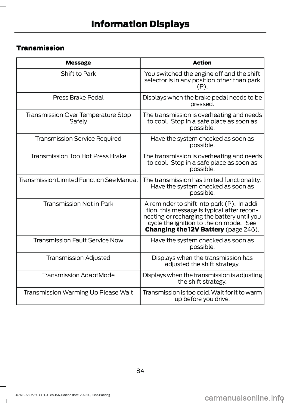
Transmission
ActionMessage
You switched the engine off and the shiftselector is in any position other than park(P).
Shift to Park
Displays when the brake pedal needs to bepressed.Press Brake Pedal
The transmission is overheating and needsto cool. Stop in a safe place as soon aspossible.
Transmission Over Temperature StopSafely
Have the system checked as soon aspossible.Transmission Service Required
The transmission is overheating and needsto cool. Stop in a safe place as soon aspossible.
Transmission Too Hot Press Brake
The transmission has limited functionality.Have the system checked as soon aspossible.
Transmission Limited Function See Manual
A reminder to shift into park (P). In addi-tion, this message is typical after recon-necting or recharging the battery until youcycle the ignition to the on mode. SeeChanging the 12V Battery (page 246).
Transmission Not in Park
Have the system checked as soon aspossible.Transmission Fault Service Now
Displays when the transmission hasadjusted the shift strategy.Transmission Adjusted
Displays when the transmission is adjustingthe shift strategy.Transmission AdaptMode
Transmission is too cold. Wait for it to warmup before you drive.Transmission Warming Up Please Wait
84
2024 F-650/750 (TBC) , enUSA, Edition date: 202210, First-PrintingInformation Displays
Page 102 of 386
LOCATING THE USB PORTS
Data Transfer USB Ports
The USB ports could be in the followinglocations:
•On the lower instrument panel.
•Inside the center console.
Note: These USB ports can also chargedevices.
Note: Not all USB ports in your vehicle havedata transfer capabilities.
Note: We recommend using only USB-IFcertified cables and adapters. Non-certifiedcables and adapters may not work.
Charge Only USB Ports
The USB ports could be in the followinglocations:
•On the lower instrument panel.
•On the upper instrument panel.
•Inside the media bin.
•Inside the center console.
•On the rear of the center console.
•Behind the first row seats.
•In the cargo area.
PLAYING MEDIA USING THE
USB PORT
WARNING: Driving while distractedcan result in loss of vehicle control, crashand injury. We strongly recommend thatyou use extreme caution when using anydevice that may take your focus off theroad. Your primary responsibility is thesafe operation of your vehicle. Werecommend against the use of anyhand-held device while driving andencourage the use of voice-operatedsystems when possible. Make sure youare aware of all applicable local lawsthat may affect the use of electronicdevices while driving.
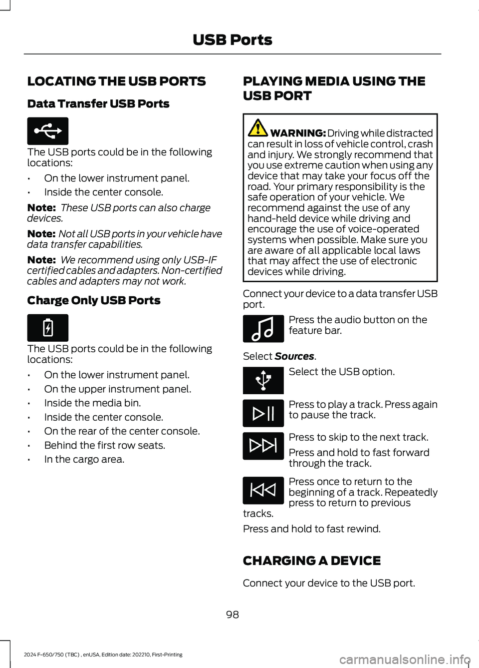
Connect your device to a data transfer USBport.
Press the audio button on thefeature bar.
Select Sources.
Select the USB option.
Press to play a track. Press againto pause the track.
Press to skip to the next track.
Press and hold to fast forwardthrough the track.
Press once to return to thebeginning of a track. Repeatedlypress to return to previoustracks.
Press and hold to fast rewind.
CHARGING A DEVICE
Connect your device to the USB port.
98
2024 F-650/750 (TBC) , enUSA, Edition date: 202210, First-PrintingUSB PortsE250655 E263583 E100027
Page 123 of 386

Illumination of the service engine soonindicator, charging system warning light orthe temperature warning light, fluid leaks,strange odors, smoke or loss of enginepower could indicate that the emissioncontrol system is not working properly.
An improperly operating or damagedexhaust system may allow exhaust toenter the vehicle. Have a damaged orimproperly operating exhaust systeminspected and repaired immediately.
Do not make any unauthorized changes toyour vehicle or engine. By law, vehicleowners and anyone who manufactures,repairs, services, sells, leases, tradesvehicles, or supervises a fleet of vehiclesare not permitted to intentionally removean emission control device or prevent itfrom working. Information about yourvehicle’s emission system is on the VehicleEmission Control Information Decallocated on or near the engine. This decalalso lists engine displacement.
Please consult your warranty informationfor complete details.
On-Board Diagnostics (OBD-II)
Your vehicle has a computer known as theon-board diagnostics system (OBD-II) thatmonitors the engine’s emission controlsystem. The system protects theenvironment by making sure that yourvehicle continues to meet governmentemission standards. The OBD-II systemalso assists a service technician in properlyservicing your vehicle.
When the service engine soonindicator illuminates, the OBD-IIsystem has detected amalfunction. Temporary malfunctions maycause the service engine soon indicator toilluminate. Examples are:
1.Your vehicle has run out of fuel—theengine may misfire or run poorly.
2.Poor fuel quality or water in thefuel—the engine may misfire or runpoorly.
3.The fuel fill inlet may not have closedproperly. See Refueling (page 112).
4.Driving through deep water—theelectrical system may be wet.
You can correct these temporarymalfunctions by filling the fuel tank withgood quality fuel, properly closing the fuelfill inlet or letting the electrical system dryout. After three driving cycles without theseor any other temporary malfunctionspresent, the service engine soon indicatorshould stay off the next time you start theengine. A driving cycle consists of a coldengine startup followed by mixed city andhighway driving. No additional vehicleservice is required.
If the service engine soon indicator remainson, have your vehicle serviced at the firstavailable opportunity. Although somemalfunctions detected by the OBD-II maynot have symptoms that are apparent,continued driving with the service enginesoon indicator on can result in increasedemissions, lower fuel economy, reducedengine and transmission smoothness andlead to more costly repairs.
Readiness for Inspection andMaintenance (I/M) Testing
Some state and provincial and localgovernments may haveInspection/Maintenance (I/M) programsto inspect the emission control equipmenton your vehicle. Failure to pass thisinspection could prevent you from gettinga vehicle registration.
If the service engine soonindicator is on or the bulb doesnot work, your vehicle may needservice. See On-Board Diagnostics.
119
2024 F-650/750 (TBC) , enUSA, Edition date: 202210, First-PrintingEngine Emission ControlE67028 E67028
Page 152 of 386
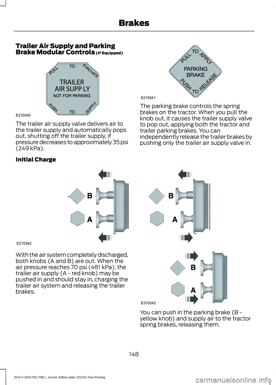
Trailer Air Supply and ParkingBrake Modular Controls (If Equipped)
The trailer air supply valve delivers air tothe trailer supply and automatically popsout, shutting off the trailer supply, ifpressure decreases to approximately 35 psi(249 kPa).
The parking brake controls the springbrakes on the tractor. When you pull theknob out, it causes the trailer supply valveto pop out, applying both the tractor andtrailer parking brakes. You canindependently release the trailer brakes bypushing only the trailer air supply valve in.
Initial Charge
With the air system completely discharged,both knobs (A and B) are out. When theair pressure reaches 70 psi (481 kPa), thetrailer air supply (A - red knob) may bepushed in and should stay in, charging thetrailer air system and releasing the trailerbrakes.
You can push in the parking brake (B -yellow knob) and supply air to the tractorspring brakes, releasing them.
148
2024 F-650/750 (TBC) , enUSA, Edition date: 202210, First-PrintingBrakesE210340AB12A320A E210341 E210342 E210343
Page 219 of 386
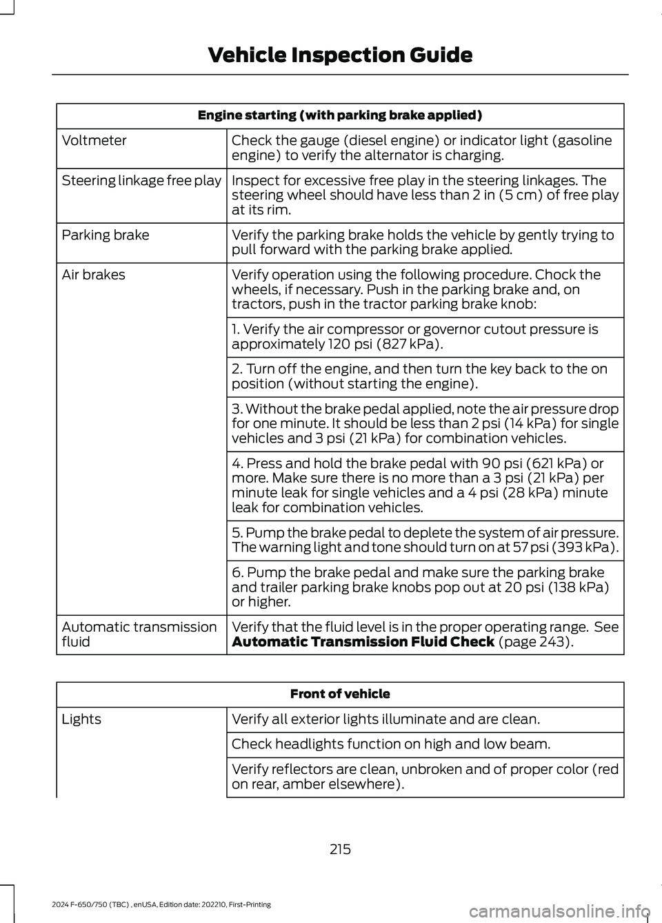
Engine starting (with parking brake applied)
Check the gauge (diesel engine) or indicator light (gasolineengine) to verify the alternator is charging.Voltmeter
Inspect for excessive free play in the steering linkages. Thesteering wheel should have less than 2 in (5 cm) of free playat its rim.
Steering linkage free play
Verify the parking brake holds the vehicle by gently trying topull forward with the parking brake applied.Parking brake
Verify operation using the following procedure. Chock thewheels, if necessary. Push in the parking brake and, ontractors, push in the tractor parking brake knob:
Air brakes
1. Verify the air compressor or governor cutout pressure isapproximately 120 psi (827 kPa).
2. Turn off the engine, and then turn the key back to the onposition (without starting the engine).
3. Without the brake pedal applied, note the air pressure dropfor one minute. It should be less than 2 psi (14 kPa) for singlevehicles and 3 psi (21 kPa) for combination vehicles.
4. Press and hold the brake pedal with 90 psi (621 kPa) ormore. Make sure there is no more than a 3 psi (21 kPa) perminute leak for single vehicles and a 4 psi (28 kPa) minuteleak for combination vehicles.
5. Pump the brake pedal to deplete the system of air pressure.The warning light and tone should turn on at 57 psi (393 kPa).
6. Pump the brake pedal and make sure the parking brakeand trailer parking brake knobs pop out at 20 psi (138 kPa)or higher.
Verify that the fluid level is in the proper operating range. SeeAutomatic Transmission Fluid Check (page 243).Automatic transmissionfluid
Front of vehicle
Verify all exterior lights illuminate and are clean.Lights
Check headlights function on high and low beam.
Verify reflectors are clean, unbroken and of proper color (redon rear, amber elsewhere).
215
2024 F-650/750 (TBC) , enUSA, Edition date: 202210, First-PrintingVehicle Inspection Guide
Page 252 of 386

the driver that battery protection actionsare active. These messages are only fornotification that an action is taking place,and not intended to indicate an electricalproblem or that the battery requiresreplacement.
Electrical accessory installation
To ensure proper operation of the BMS,any electrical devices that are added tothe vehicle should not have their groundconnection made directly at the negativebattery post. A connection at the negativebattery post can cause inaccuratemeasurements of the battery conditionand potential incorrect system operation.
Note:Electrical or electronic accessoriesadded to the vehicle by the dealer or theowner may adversely affect batteryperformance and durability, and may alsoaffect the performance of other electricalsystems in the vehicle.
When a battery replacement is required,the battery should only be replaced witha Ford recommended replacement batterywhich matches the electrical requirementsof the vehicle. After battery replacement,or in some cases after charging the batterywith the external charger, the BMS requireseight hours of vehicle sleep time (key offwith doors closed) to relearn the newbattery state of charge. Prior to relearningthe state of charge, the BMS may disableelectrical features (to protect the battery)earlier than normal.
ADJUSTING THE HEADLAMPS
Vertical Aim Adjustment
The headlamps on your vehicle areproperly aimed at the assembly plant. Ifyour vehicle has been in an accident, thealignment of your headlamps should bechecked by your authorized dealer.
Headlamp Aiming Target
8 ft (2.4 m)A
Center height of lamp to groundB
25 ft (7.6 m)C
Horizontal reference lineD
Vertical Aim Adjustment Procedure
1.Park the vehicle directly in front of awall or screen on a level surface,approximately 25 ft (7.6 m) away.
2.Measure the height of the headlampbulb center from the ground and markan 8 ft (2.4 m) horizontal reference lineon the vertical wall or screen at thisheight.
Note:To see a clearer light pattern foradjusting, you may want to block the lightfrom one headlamp while adjusting theother.
3.Turn on the low beam headlamps toilluminate the wall or screen and openthe hood.
248
2024 F-650/750 (TBC) , enUSA, Edition date: 202210, First-PrintingMaintenanceE142592