Page 465 of 698
463
7
Owners Manual_Europe_M52N75_en
7-2. Steps to take in an emergency
When trouble arises
recessed portion of the jack is in
contact with the center of the
jack point.
5 Assemble the jack handle
extension.
6 Raise the vehicle until the tire is
slightly raised off the ground.
7 Remove all the wheel nuts and
the tire.
When resting the tire on the ground, place the tire so that the wheel design faces up to avoid scratching the wheel
surface.
WARNING
■Replacing a flat tire
●Observe the following precautions.
Failure to do so may result in seri- ous injury:
• Do not try to remove the wheel ornament by hand. Take due care in handling the ornament to avoid
unexpected personal injury.
Page 466 of 698
464
Owners Manual_Europe_M52N75_en
7-2. Steps to take in an emergency
1Remove any dirt or foreign mat-
ter from the wheel contact sur-
face.
If foreign matter is on the wheel contact
surface, the wheel nuts may loosen while the vehicle is in motion, causing the tire to come off.
2 Install the tire and loosely
tighten each wheel nut by hand
by approximately the same
amount.
When replacing a steel wheel with a
steel wheel (including a compact spare
tire), tighten the wheel nuts until the
tapered portion comes into loose
contact with the disc wheel seat .
When replacing an aluminum wheel
with a steel wheel (including a compact
spare tire), tighten the wheel nuts until
the tapered portion comes into
loose contact with the disc wheel seat
WARNING
�
Page 467 of 698

465
7
Owners Manual_Europe_M52N75_en
7-2. Steps to take in an emergency
When trouble arises
.
When replacing an aluminum wheel
with an aluminum wheel, turn the wheel
nuts until the washers come into
contact with the disc wheel .
3 Lower the vehicle.
4 Firmly tighten each wheel nut
two or three times in the order
shown in the illustration.
Tightening torque:
103 N•m (10.5 kgf•m, 76 ft•lbf)
5 Stow the flat tire, tire jack and all
tools.
■The full-size spare tire (if equipped)
●The full-size spare tire has a “Tempo- rary use only” label on the outer sur-
face of the wheel. Use the full-size spare tire temporarily, and only in an emergency.
●Make sure to check the tire inflation pressure of the full-size spare tire.
( P.490)
■The compact spare tire (if equipped)
●The compact spare tire is identified by the label “TEMPORARY USE ONLY” on the tire sidewall. Use the compact
spare tire temporarily, and only in an emergency.
●Make sure to check the tire inflation pressure of the compact spare tire. ( P.490)
■When the compact spare tire (if
equipped) is equipped
The vehicle becomes lower when driv- ing with the compact spare tire com-
pared to when driving with standard tires.
■When using the compact spare tire
(if equipped)
As the compact spare tire is not equipped with a tire pressure warning
valve and transmitter, low inflation pres- sure of the compact spare tire will not be indicated by the tire pressure warning
Page 468 of 698

466
Owners Manual_Europe_M52N75_en
7-2. Steps to take in an emergency
system. Also, if you replace the compact
spare tire after the tire pressure warning light comes on, the light remains on.
■If you have a flat rear tire (vehicles
with a compact spare tire in some
countries*)
Do not install the compact spare tire to rear axles.
Install the compact spare tire on one of the front wheels of the vehicle.
1 Replace a front tire with the compact spare tire.
2 Replace the flat rear tire with the tire
removed from the front of the vehi- cle.*: Guadelope, Martinique, F. Guiana,
Ceuta & Melilla, Ukraine, Turkey, New
Caledonia, Tahiti, Morocco
■If you have a flat front tire on a road covered with snow or ice (vehicles
with a compact spare tire)
Install the compact spare tire on one of the rear wheels of the vehicle. Perform
the following steps and fit tire chains to the front tires:
1 Replace a rear tire with the compact spare tire.
2 Replace the flat front tire with the tire
removed from the rear of the vehicle.
3 Fit tire chains to the front tires.
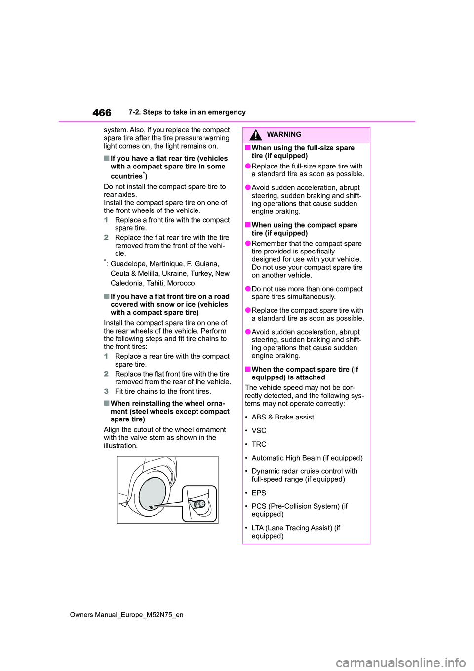
■When reinstalling the wheel orna- ment (steel wheels except compact spare tire)
Align the cutout of the wheel ornament with the valve stem as shown in the illustration.
WARNING
■When using the full-size spare tire (if equipped)
●Replace the full-size spare tire with a standard tire as soon as possible.
●Avoid sudden acceleration, abrupt steering, sudden braking and shift-ing operations that cause sudden
engine braking.
■When using the compact spare
tire (if equipped)
●Remember that the compact spare tire provided is specifically
designed for use with your vehicle. Do not use your compact spare tire on another vehicle.
●Do not use more than one compact spare tires simultaneously.
●Replace the compact spare tire with a standard tire as soon as possible.
●Avoid sudden acceleration, abrupt steering, sudden braking and shift-
ing operations that cause sudden engine braking.
■When the compact spare tire (if equipped) is attached
The vehicle speed may not be cor-
rectly detected, and the following sys- tems may not operate correctly:
• ABS & Brake assist
• VSC
•TRC
• Automatic High Beam (if equipped)
• Dynamic radar cruise control with
full-speed range (if equipped)
• EPS
• PCS (Pre-Collision System) (if equipped)
• LTA (Lane Tracing Assist) (if equipped)
Page 482 of 698
480
Owners Manual_Europe_M52N75_en
7-2. Steps to take in an emergency
1Stop the hybrid system. Set the
parking brake and shift the shift
lever to P.
2 Remove the mud, snow or sand
from around the front wheels.
3 Place wood, stones or some
other material under the front
wheels to help provide traction.
4 Restart the hybrid system.
5 Shift the shift lever to D or R and
release the parking brake. Then,
while exercising caution,
depress the accelerator pedal.
■When it is difficult to free the vehi-
cle
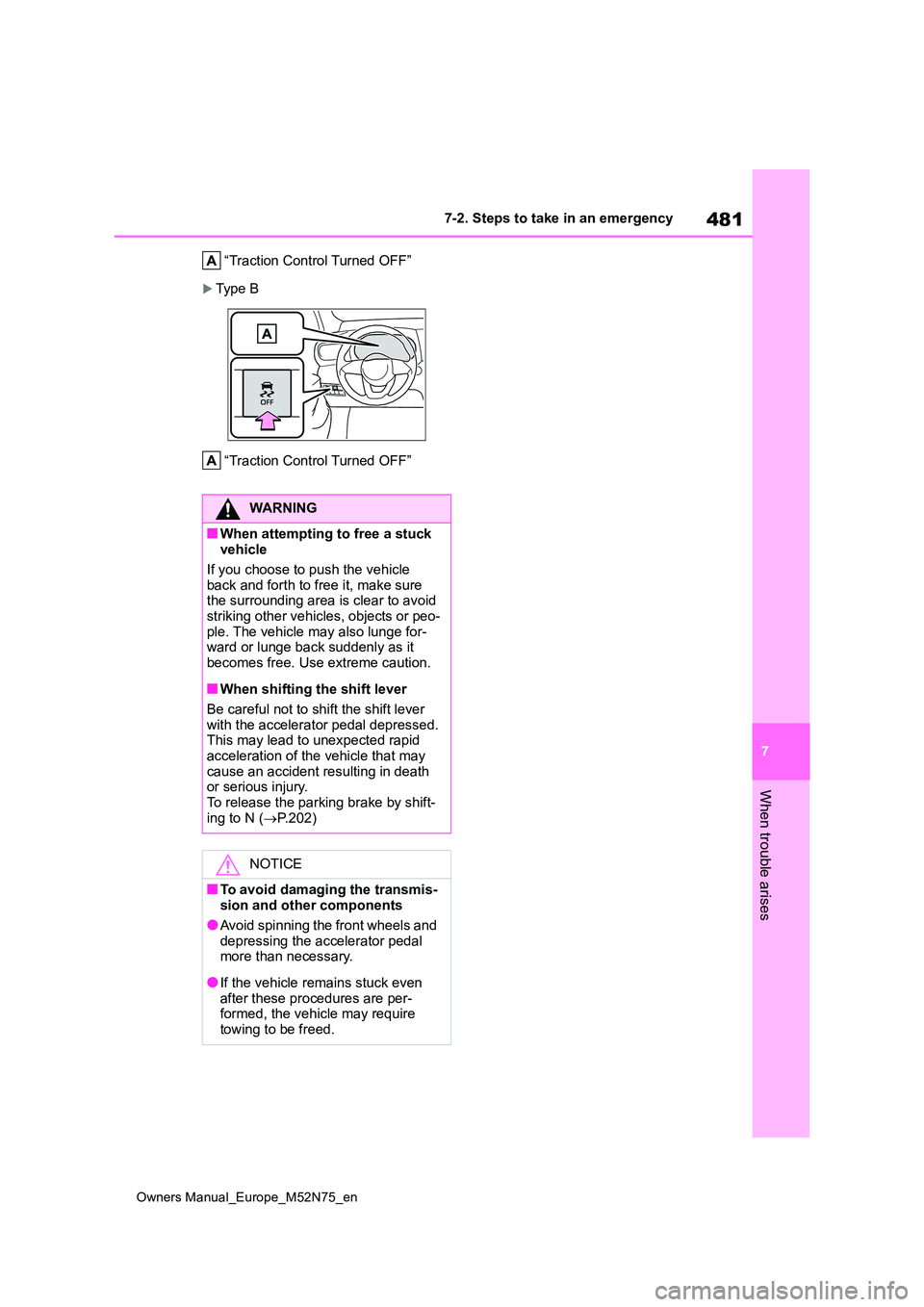
Press the switch to turn off TRC.
A message will be shown on the multi-
information display.
Ty p e A
NOTICE
●Do not use any coolant additive.
If the vehicle becomes
stuck
Carry out the following proce-
dures if the tires spin or the
vehicle becomes stuck in mud,
dirt or snow:
Recovering procedure
Page 483 of 698

481
7
Owners Manual_Europe_M52N75_en
7-2. Steps to take in an emergency
When trouble arises
“Traction Control Turned OFF”
Typ e B
“Traction Control Turned OFF”
WARNING
■When attempting to free a stuck vehicle
If you choose to push the vehicle
back and forth to free it, make sure the surrounding area is clear to avoid striking other vehicles, objects or peo-
ple. The vehicle may also lunge for- ward or lunge back suddenly as it becomes free. Use extreme caution.
■When shifting the shift lever
Be careful not to shift the shift lever
with the accelerator pedal depressed. This may lead to unexpected rapid acceleration of the vehicle that may
cause an accident resulting in death or serious injury.To release the parking brake by shift-
ing to N ( P.202)
NOTICE
■To avoid damaging the transmis- sion and other components
●Avoid spinning the front wheels and
depressing the accelerator pedal more than necessary.
●If the vehicle remains stuck even after these procedures are per-formed, the vehicle may require
towing to be freed.
Page 486 of 698

484
Owners Manual_Europe_M52N75_en
8-1. Specifications
8-1.Spec ific ations
*1: With front bumper type A (P.431)
*2: With front bumper type B (P.431)
*3: 17-inch tires or 18-inch tires
*4: 16-inch tires
*5: 17-inch tires or 18-inch tires and AWD models
*6: 16-inch tires and AWD models
*7: 17-inch tires or 18-inch tires and 2WD models
*8: 16-inch tires and 2WD models
*9: 2WD models
*10: AWD models
Maintenance data (fuel, oil level, etc.)
Dimensions and weights
Overall length4180 mm (164.6 in.)*1
4200 mm (165.4 in.)*2
Overall width1765 mm (69.5 in.)
Overall height (unladen vehicles)1595 mm (62.8 in.)
Wheelbase2560 mm (100.8 in.)
Tread
Front1517 mm (59.7 in.)*3
1527 mm (60.1 in.)*4
Rear
1504 mm (59.2 in.)*5
1514 mm (59.6 in.)*6
1517 mm (59.7 in.)*7
1527 mm (60.1 in.)*8
Gross vehicle mass1690 kg (3726.4 lb.)*9
1775 kg (3913.8 lb.)*10
Maximum permissible axle
capacity
Front965 kg (2127.8 lb.)
Rear925 kg (2039.6 lb.)
Drawbar load (vehicles with towing packages)75 kg (165.3 lb.)
Towing capacity (vehicles with
towing packages)
Without brake550 kg (1212.7 lb.)
With brake750 kg (1653.7 lb.)
Page 492 of 698

490
Owners Manual_Europe_M52N75_en
8-1. Specifications
If replacement is necessary, contact any authorized Toyota reta iler or Toyota
authorized repairer, or any reliable repairer.
*1: Minimum pedal clearance when depressed with a force of 300 N ( 31.0 kgf, 67.4
lbf) while the hybrid system is operating.
*2: Make sure to confirm that the brake warning light (yellow) doe s not illuminate. (If
the brake warning light illuminates, refer to P.91, 435.)
16-inch tires
NOTICE
■Transmission fluid type
Using transmission fluid other than the above type may cause ab normal noise or vibration, or ultimately damage the transmission of your vehicl e.
Brakes
Pedal clearance*188 mm (3.5 in.) Min.
Pedal free play1 6 mm (0.04 0.24 in.)
Parking brake indicator*2
When pulling the parking brake switch for 1 to 2
seconds: comes on
When pushing the parking brake switch for 1 to
2 seconds: turns off
Fluid typeSAE J1704 or FMVSS No.116 DOT 4
Steering
Free playLess than 30 mm (1.2 in.)
Tires and wheels
Tire size205/65R16 95H
Tire inflation pressure
(Recommended cold tire
inflation pressure)
Front tire
230 kPa (2.3 kgf/cm2 or bar, 33 psi)
Rear tire
220 kPa (2.2 kgf/cm2 or bar, 32 psi)
Wheel size16 6 1/2J
Wheel nut torque103 N•m (10.5 kgf•m, 76 ft•lbf)