2023 TOYOTA 86 ECU
[x] Cancel search: ECUPage 343 of 449
3437-2. Steps to take in an emergency
7
When trouble arises
Use a towing dolly under the
front wheels.
When using a flat-bed truck to
transport the vehicle, use tire
strapping belts. Refer to the
owner’s manual of the flat-bed
truck for the tire strapping
method.
In order to suppress vehicle
movement during transporta-
tion, set the parking brake and
turn the engine switch off.
If a tow truck is not available in
an emergency, your vehicle may
be temporarily towed using
cables or chains secured to the
emergency towing eyelets. This
should only be attempted on
hard surfaced roads for at most
19 miles (30 km) at under 18
mph (30 km/h).
A driver must be in the vehicle to steer and operate the brakes.
The vehicle’s wheels, drive train,
axles, steering and brakes must
be in good condition.
For vehicles with an automatic
transmission, only the front tow-
ing eyelets may be used.
To have your vehicle towed by
another vehicle, the towing eye-
let must be installed to your
vehicle. Install the towing eyelet
using the following procedure.
1
Take out the wheel nut
wrench, flathead screwdriver
and towing eyelet. ( P.359)
2 Remove the eyelet cover
using a flathead screwdriver.
To protect the b odywork, place a
rag between the screwdriver and
the vehicle body as shown in the
NOTICE
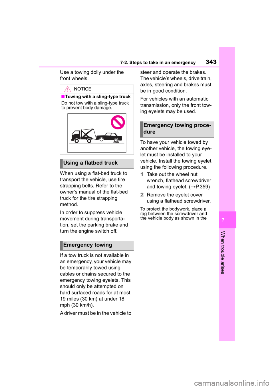
■Towing with a sling-type truck
Do not tow with a sling-type truck
to prevent body damage.
Using a flatbed truck
Emergency towing
Emergency towing proce-
dure
Page 344 of 449
3447-2. Steps to take in an emergency
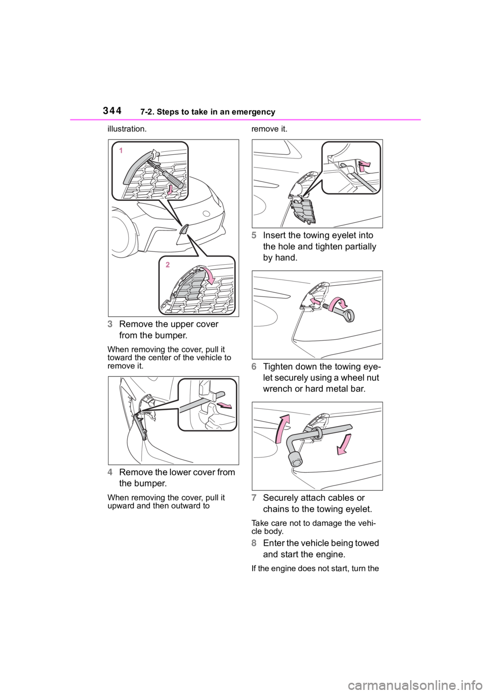
illustration.
3Remove the upper cover
from the bumper.
When removing the cover, pull it
toward the center of the vehicle to
remove it.
4Remove the lower cover from
the bumper.
When removing the cover, pull it
upward and then outward to remove it.
5
Insert the towing eyelet into
the hole and tighten partially
by hand.
6 Tighten down the towing eye-
let securely using a wheel nut
wrench or hard metal bar.
7 Securely attach cables or
chains to the towing eyelet.
Take care not to damage the vehi-
cle body.
8Enter the vehicle being towed
and start the engine.
If the engine does not start, turn the
Page 345 of 449
3457-2. Steps to take in an emergency
7
When trouble arises
engine switch to ON.
9Shift the shift lever to N and
release the parking brake.
Vehicles with an automatic trans-
mission: When the shift lever can-
not be shifted: P. 1 5 0
■Towing eyelet purpose
The towing eyelet i s to be used to
tow your vehicle, not to tow other
vehicles.
■While towing
If the engine is not running, the
power assist for the brakes and
steering will not function, making
steering and braking more difficult.
■Wheel nut wrench
Wheel nut wrench is installed in
trunk. ( P.359)
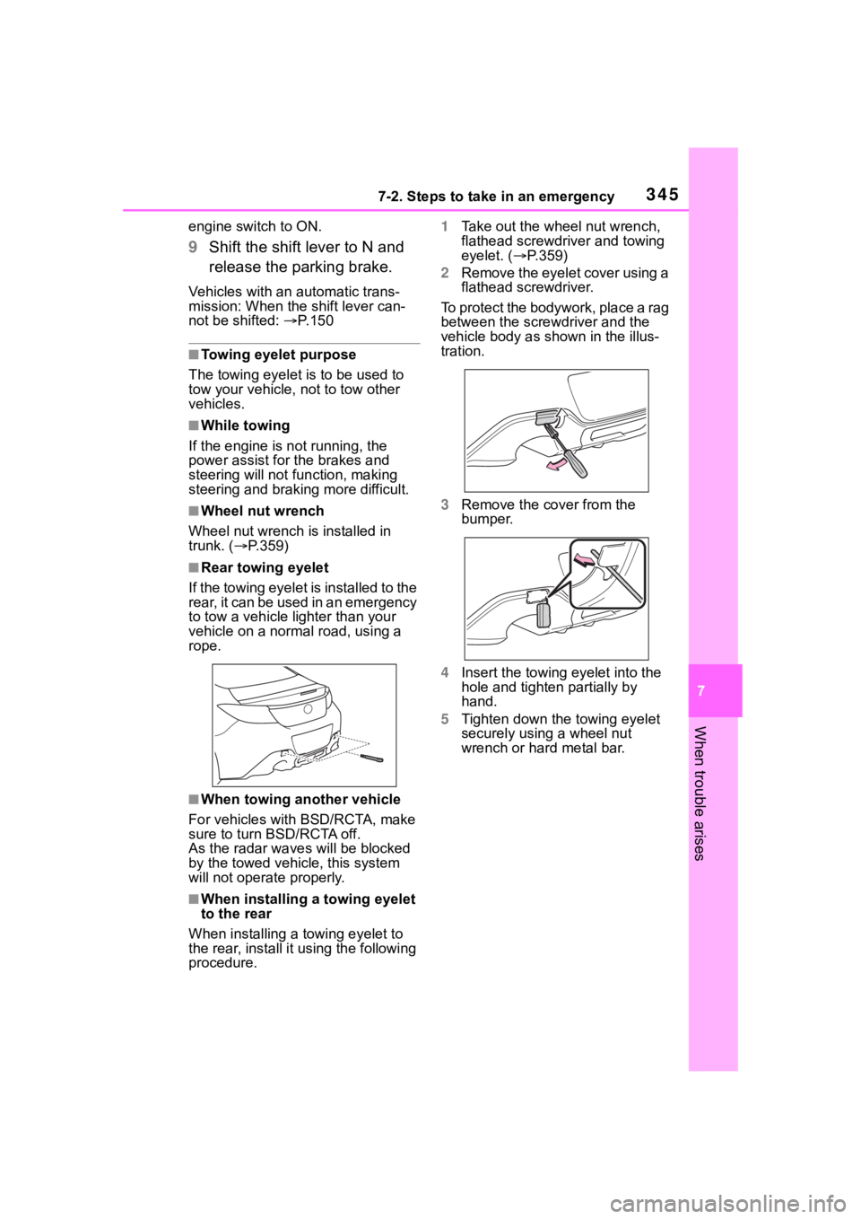
■Rear towing eyelet
If the towing eyelet is installed to the
rear, it can be used in an emergency
to tow a vehicle lig hter than your
vehicle on a norma l road, using a
rope.
■When towing another vehicle
For vehicles with BSD/RCTA, make
sure to turn BSD/RCTA off.
As the radar wave s will be blocked
by the towed vehicle, this system
will not operat e properly.
■When installing a towing eyelet
to the rear
When installing a towing eyelet to
the rear, install it using the following
procedure. 1
Take out the wheel nut wrench,
flathead screwdriver and towing
eyelet. ( P.359)
2 Remove the eyelet cover using a
flathead screwdriver.
To protect the bodywork, place a rag
between the screwdriver and the
vehicle body as shown in the illus-
tration.
3 Remove the cover from the
bumper.
4 Insert the towing eyelet into the
hole and tighten partially by
hand.
5 Tighten down the towing eyelet
securely using a wheel nut
wrench or hard metal bar.
Page 354 of 449

3547-2. Steps to take in an emergency
■Tire pressure warning light (warning buzzer)
■Front passenger detection sen-
sor, seat belt reminder and
warning buzzer
●If luggage is placed on the front
passenger seat, the front passen-
ger detection sensor may cause
the warning light to flash and the
warning buzzer to sound even if a
passenger is not sitting in the
seat.
●If a cushion is placed on the seat,
the sensor may not detect a pas-
senger, and the warning light may
not operate properly.
■If the malfunction indicator
lamp comes on while driving
First check the following:
●Is the fuel t ank empty?
If it is, fill the f uel tank immediately.
●Is the fuel tank cap loose?
If it is, tighten it securely.
The light will go o ff after several
driving trips.
If the light does not go off even after
several trips, contact your Toyota
dealer as soon as possible.
■Electric power steering system
warning light (warning buzzer)
When the battery charge becomes
insufficient or the voltage temporar-
ily drops, the electric power steering
system warning light may come on
and the warning buzzer may sound.
■When the tire pressure warning
light comes on
Check the tire inflation pressure and
adjust to the appropriate level.
Pushing the tire pressure warning
reset switch will not turn off the tire
pressure warning light.
■The tire pressure warning light
may come on due to natural
causes
The tire pressure warning light may
come on due to natural causes such
as natural air leaks and tire inflation
pressure changes caused by tem-
perature. In this ca se, adjusting the
tire inflation pressure will turn off the
warning ligh t (after a few minutes).
■Conditions that the tire pres-
sure warning system may not
function properly
P.315
Warning lightDetails/Actions
When the light comes on:
Low tire inflation pressure such as
Natural causes ( P.354)
Flat tire ( P.358)
Adjust the tir e inflation pressure to the specified
level. The light will turn of f after a few minutes. In
case the light does not turn off even if the tire infla-
tion pressure is adjusted, have the system checked
by your Toyota dealer.
When the light comes on a fter blinking for 1 minute:
Malfunction in the tire pressure warning system
Have the system checked by your Toyota dealer.
Page 366 of 449
3667-2. Steps to take in an emergency
WARNING
●Connect the valve and hose
securely with the tire installed
on the vehicle.
●If the hose is not properly con-
nected to the valve, air leakage
may occur or sealant may be
sprayed out.
●If the hose comes off the valve
while inflating the tire, there is a
risk that the hose will move
abruptly due to air pressure.
●After inflation of the tire has
completed, the sealant may
splatter when the hose is dis-
connected or some air is let out
of the tire.
●Follow the operation procedure
to repair the tire. If the proce-
dure is not followed, the sealant
may spray out.
●Keep back from the tire while it
is being repaired, as there is a
chance of it bursting while the
repair operation is being per-
formed. If you notice any cracks
or deformation of the tire, turn
off the compressor switch and
stop the repair operation imme-
diately.
●The kit may overheat if operated
for a long period of time. Do not
operate the compressor contin-
uously for more than 10 min-
utes.
●Parts of the kit become hot
during operation. Be careful
handling the kit during and after
operation. Do not touch the
metal part around the connect-
ing area between the bottle and
compressor. It will be extremely
hot.
●Do not attach the vehicle speed
warning sticker to an area other
than the one indicated. If the
sticker is attached to an area
where an SRS airbag is located,
such as the pad of the steering
wheel, it may prevent the SRS
airbag from operating properly.
■Driving to spread the liquid
sealant evenly
Observe the following precautions
to reduce the risk of accidents.
Failing to do so may result in a
loss of vehicle control and cause
death or serious injury.
●Drive the vehicle carefully at a
low speed. Be especially careful
when turning and cornering.
●If the vehicle does not drive
straight or you feel a pull
through the steering wheel, stop
the vehicle and check the tire.
The tire may have separated
from the wheel.
NOTICE
■When performing an emer-
gency repair
●Perform the emergency repair
without removing the nail or
screw that has punctured the
tread of the tire. If the object
that has punctur ed the tire is
removed, repair by the emer-
gency tire puncture repair kit
may not be possible.
●The kit is not waterproof. Make
sure that the ki t is not exposed
to water, such as when it is
being used in the rain.
●Do not put the kit directly onto
dusty ground such as sand at
the side of the road. If the kit
vacuums up dust etc., a mal-
function may occur.
Page 373 of 449
3737-2. Steps to take in an emergency
7
When trouble arises
Connect the jumper cable to ground on your vehicle as shown in
the illustration.
4 Start the engine of the sec-
ond vehicle. Increase the
engine speed slightly and
maintain at that level for
approximately 5 minutes to
recharge the battery of your
vehicle.
5 Open and close any of the
door of your vehicle with the
engine switch off.
6 Maintain the engine speed of
the second vehicle and start
the engine of your vehicle by
turning the engine switch to
ON.
7 Once the vehicle’s engine
has started, remove the
jumper cables in the exact
reverse order from which
they were connected.
Once the engine starts, have the
vehicle inspected at your Toyota
dealer as soon as possible.
■Starting the engine when the
battery is discharged
The engine cannot be started by
push-starting.
■To prevent battery discharge
●Turn off the headlights and the
audio system while the engine is
off.
●Turn off any unnecessary electri-
cal components when the vehicle
is running at a low speed for an
extended period, such as in heavy
traffic.
■When the battery is removed or
discharged
Information stored in the ECU is
cleared. When the battery is
depleted, have the vehicle
inspected at your Toyota dealer.
■When removing the battery ter-
minals
When the battery terminals are
removed, the information stored in
the ECU is cleared. Before remov-
ing the battery term inals, contact
your Toyota dealer.
■Charging the battery
The electricity stored in the battery
will discharge grad ually even when
the vehicle is not in use, due to nat-
ural discharge and the draining
effects of certain electrical appli-
ances. If the vehicle is left for a long
time, the battery may discharge,
and the engine may be unable to
start. (The battery recharges auto-
matically during driving.)
■When recharging or replacing
the battery
●In some cases, it may not be pos-
sible to unlock the doors using the
smart key system when the bat-
tery is discharged. Use the wire-
less remote control or the
mechanical key to lock or unlock
the doors.
●The engine may not start on the
first attempt after the battery has
recharged but will start normally
after the second attempt. This is
not a malfunction.
●The engine switch mode is memo-
rized by the vehicle. When the
battery is reconnected, the system
will return to the mode it was in
before the bat tery was dis-
charged. Before disconnecting the
battery, turn the engine switch off.
If you are unsure what mode the
engine switch wa s in before the
D
Page 398 of 449
3988-1. Specifications
*: Table 1 - Occupant loading and distribution for vehicle normal load for
various designated seating capacities
Sidewall separationThe parting of the rubber compound from
the cord materia l in the sidewall
Snow tire
A tire that attains a traction index equal to
or greater than 110, compared to the
ASTM E-1136 Standard Reference Test
Tire, when using the snow traction test as
described in ASTM F-1805-00, Standard
Test Method for Single Wheel Driving Trac-
tion in a Straight Line on Snow-and
Ice-Covered Surfaces, and which is
marked with an Alpi ne Symbol ( ) on
at least one sidewall
Te s t r i m
The rim on which a tire is fitted for testing,
and may be any rim lis ted as appropriate
for use with that tire
TreadThat portion of a tire that comes into con-
tact with the road
Tread ribA tread section running circumferentially
around a tire
Tread separationPulling away of the tread from the tire car-
cass
Treadwear indicators (TWI)
The projections wit hin the principal
grooves designed to g ive a visual indica-
tion of the degrees of wear of the tread
Wheel-holding fixtureThe fixture used to hol d the wheel and tire
assembly securely during testing
Tire related termMeaning
Designated seating
capacity, Number of occupantsVehicle normal load,
Number of occupantsOccupant distribution in a normally loaded vehi- cle
2 through 422 in front
5 through 1032 in front, 1 in second seat
Page 409 of 449
4099-1. For owners
9
For owners
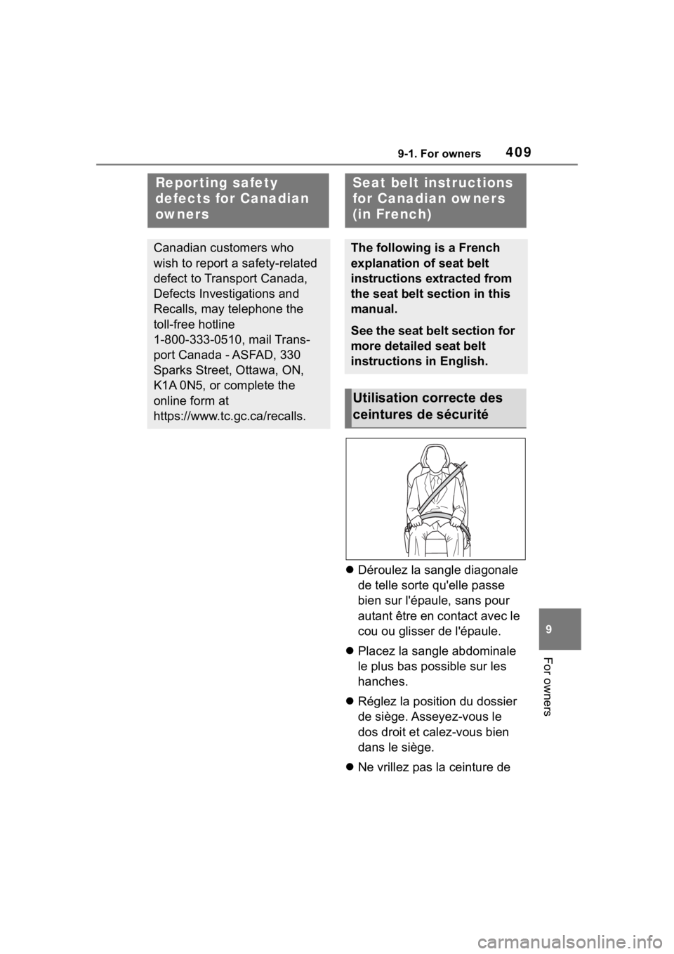
Déroulez la sangle diagonale
de telle sorte qu'elle passe
bien sur l'épaule, sans pour
autant être en contact avec le
cou ou glisser de l'épaule.
Placez la sangle abdominale
le plus bas possible sur les
hanches.
Réglez la position du dossier
de siège. Asseyez-vous le
dos droit et calez-vous bien
dans le siège.
Ne vrillez pas la ceinture de
Repor ting safety
defects for Canadian
owners
Canadian customers who
wish to report a safety-related
defect to Transport Canada,
Defects Investigations and
Recalls, may telephone the
toll-free hotline
1-800-333-0510, mail Trans-
port Canada - ASFAD, 330
Sparks Street, Ottawa, ON,
K1A 0N5, or complete the
online form at
https://www.tc.gc.ca/recalls.
Seat belt instructions
for Canadian owners
(in French)
The following is a French
explanation of seat belt
instructions extracted from
the seat belt section in this
manual.
See the seat belt section for
more detailed seat belt
instructions in English.
Utilisation correcte des
ceintures de sécurité