2023 TOYOTA 86 engine
[x] Cancel search: enginePage 242 of 449
2424-6. Using other driving systems
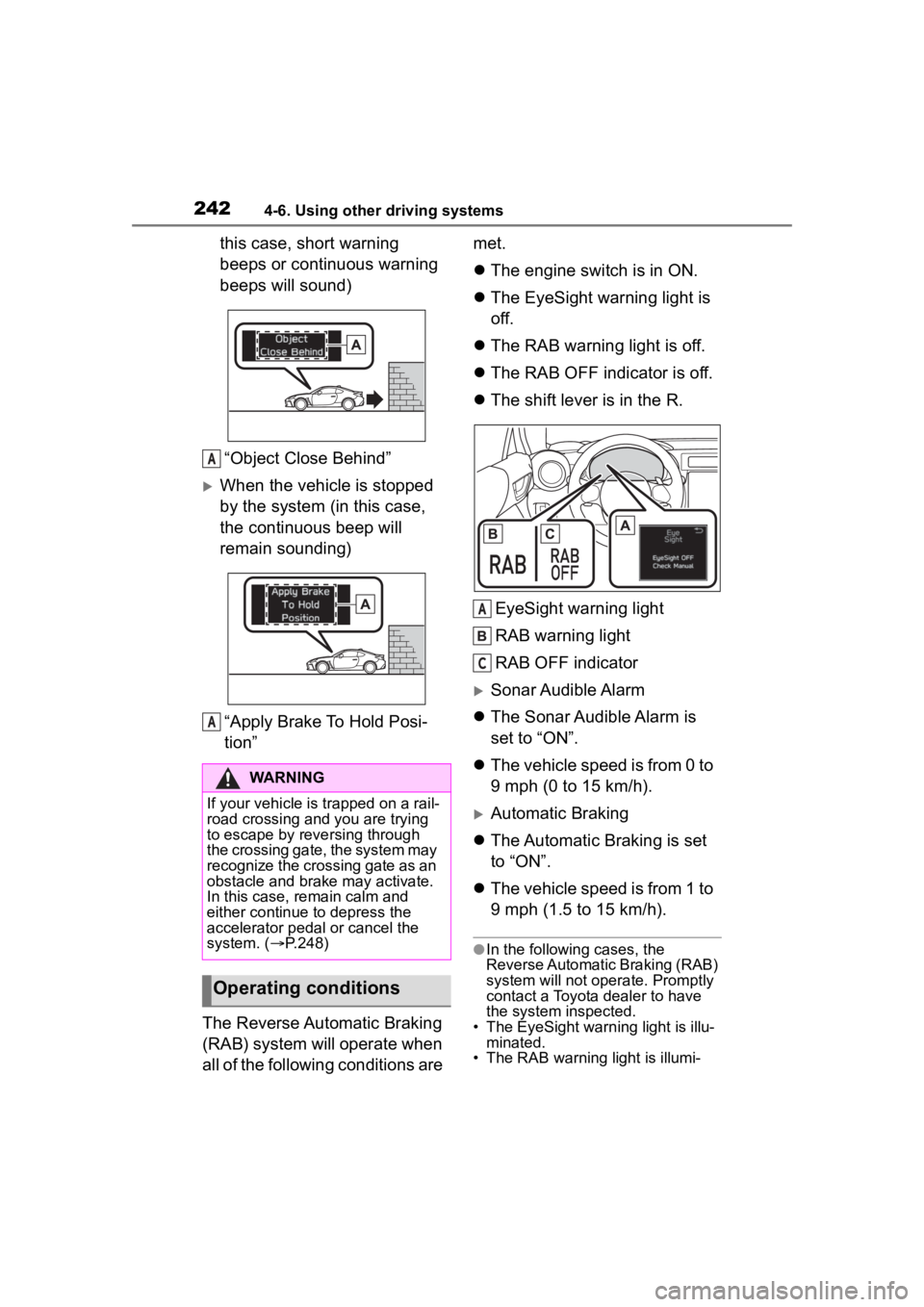
this case, short warning
beeps or continuous warning
beeps will sound)“Object Close Behind”
When the vehicle is stopped
by the system (in this case,
the continuous beep will
remain sounding)“Apply Brake To Hold Posi-
tion”
The Reverse Automatic Braking
(RAB) system will operate when
all of the following conditions are met.
The engine switch is in ON.
The EyeSight warning light is
off.
The RAB warning light is off.
The RAB OFF indicator is off.
The shift lever is in the R.
EyeSight warning light
RAB warning light
RAB OFF indicator
Sonar Audible Alarm
The Sonar Audible Alarm is
set to “ON”.
The vehicle speed is from 0 to
9 mph (0 to 15 km/h).
Automatic Braking
The Automatic Braking is set
to “ON”.
The vehicle speed is from 1 to
9 mph (1.5 to 15 km/h).
●In the following cases, the
Reverse Automatic Braking (RAB)
system will not oper ate. Promptly
contact a Toyota dealer to have
the system inspected.
• The EyeSight warning light is illu- minated.
• The RAB warning light is illumi-
WARNING
If your vehicle is trapped on a rail-
road crossing and you are trying
to escape by reve rsing through
the crossing gate, the system may
recognize the crossing gate as an
obstacle and brake may activate.
In this case, rem ain calm and
either continue to depress the
accelerator pedal or cancel the
system. ( P.248)
Operating conditions
A
A
A
C
Page 243 of 449

2434-6. Using other driving systems
4
Driving
nated.
●In the following cases, the
Reverse Automatic Braking (RAB)
system cannot be operated.
• The RAB OFF indicator is illumi-
nated.
●In the following cases, the func-
tions may not be able to properly
work. Promptly contact a Toyota
dealer to have the system
inspected.
• A sticker, paint, or a chemical is applied to the sonar sensors or
the rear bumper near the sonar
sensor.
• The rear bumper is modified.
• The rear bumper has been
removed and attached.
• The ground clearance is changed
due to the vehicle’s loading condi-
tion or modification.
• There is damage to the sonar sen-
sors or the rear bumper near the
sonar sensor.
• The rear bumper is exposed to
strong impact, or the rear bumper
is deformed.
●On a steep hill, t he system’s auto-
matic braking ability will be
reduced.
●The system is designed to avoid
collisions by automatic hard brak-
ing when the vehicle’s reversing
speed is less than approximately
3 mph (5 km/h). However, the sys-
tem does not guarantee that the
vehicle will be able to avoid colli-
sions in any situation.
●If the vehicle is reversed at an
extremely slow speed, the driver’s
operation may be prioritized. In
this case, automatic braking will
not operate.
●The system may not be able to
detect and apply the brake with
the following objects.
• Sharp or thin objects such as poles, fences and ropes which
may not reflect the sound wave
emitted from the sonar sensor.
• Objects that are t oo close to the
rear bumper when the shift lever is set to R.
• Objects with a su rface which may
not reflect the sound wave emitted
from the sonar sensor such as a
chain link fence.
●Objects the system is not
designed to detect and apply
brake.
• Pedestrians.
• Moving objects including moving vehicles.
• Objects which absorbs sound waves such as cloth or snow.
• Objects whose surface has a
diagonal angle.
• Objects that are low to the ground such as parking blocks.
• Objects that are high above the ground such as objects hanging
from above.
• Objects that are out of range of
the center of the vehicle in the
horizontal direction.
• Objects that are n ot in a vertical
direction.
• Objects which are not perpendicu-
lar to the ground.
• Objects which are not directly in the traveling direction of the vehi-
cle.
• Objects which a re uneven or
wavy.
●When reversing the vehicle, the
functions may not be able to work
properly or may cause a system
malfunction if the following condi-
tions exist.
High frequency so und from other
sources are nearby:
• Horn sound from another vehicle.
• Engine sound from other vehicles.
• Sound of an air brake.
• Vehicle detection equipment or a
sonar from another vehicle.
• A sound wave with a frequency similar to the veh icle’s system is
transmitted near by.
• A vehicle equipped with the same system is reversing toward your
reversing direction.
●Weather conditions:
• Extremely high or extremely low
Page 245 of 449
2454-6. Using other driving systems
4
Driving
●In circumstances such as the fol-
lowing, it may not be possible to
avoid a collision even when the
system operate s normally.
• Roads are slippery.
• The tire air pressure is not correct.
• The tires have become worn.
• Tire chains are installed.
• Tires which are not the designated size are installed.
• Emergency repairs were per- formed using a puncture repair kit.
• The suspension was modified.
• Vehicle driving is unstable due to accident or malfunction.
• The brake system warning light is
illuminated.
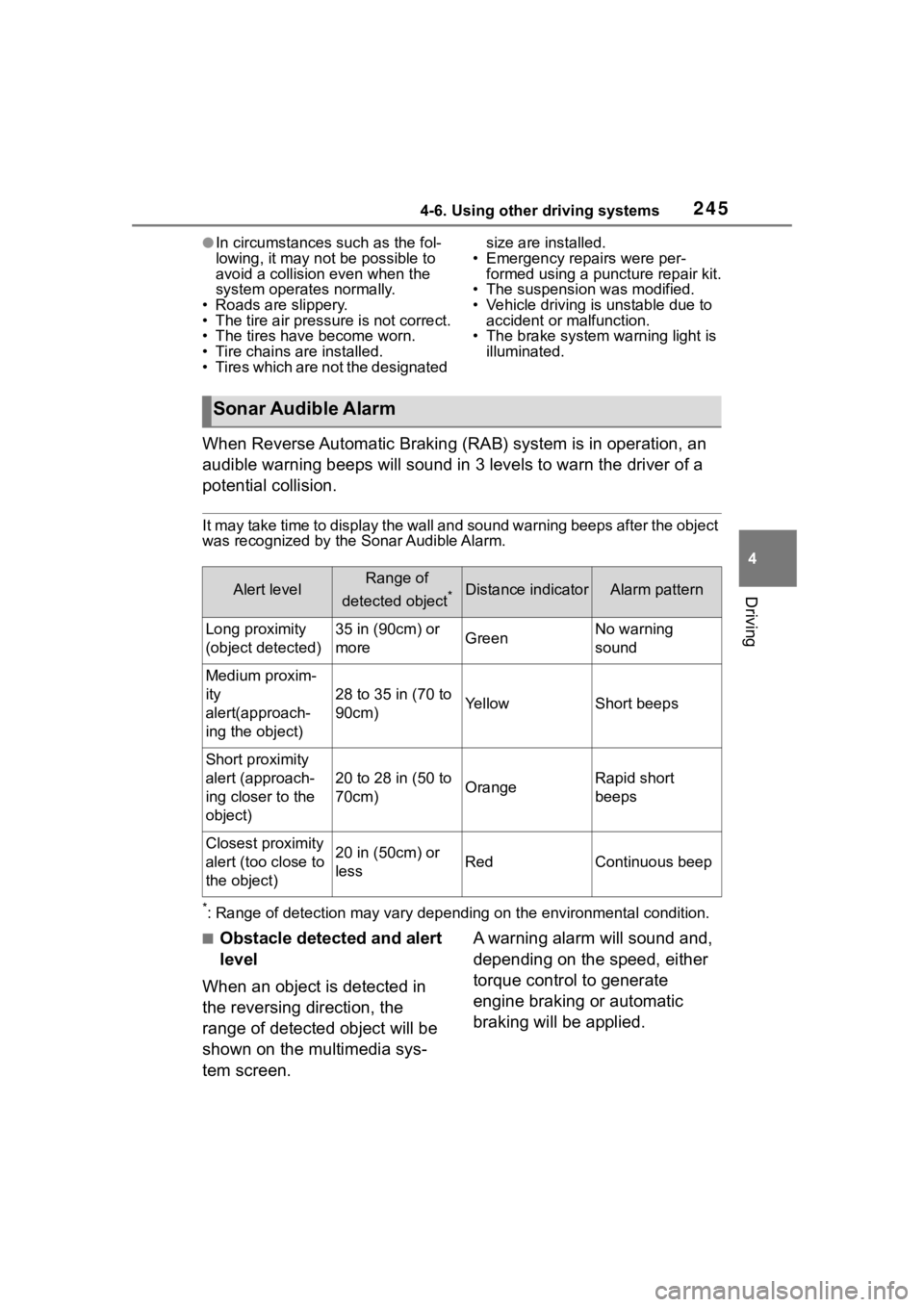
When Reverse Automatic Braking (RAB) system is in operation, an
audible warning beeps will sound in 3 levels to warn the driver of a
potential collision.
It may take time to display the wall and sound warning beeps af ter the object
was recognized by the Sonar Audible Alarm.
*: Range of detection may vary d epending on the environmental condition.
■Obstacle detected and alert
level
When an object is detected in
the reversing direction, the
range of detected object will be
shown on the multimedia sys-
tem screen. A warning alarm will sound and,
depending on the speed, either
torque control to generate
engine braking or automatic
braking will be applied.
Sonar Audible Alarm
Alert levelRange of
detected object
*Distance indicatorAlarm pattern
Long proximity
(object detected)35 in (90cm) or
moreGreenNo warning
sound
Medium proxim-
ity
alert(approach-
ing the object)
28 to 35 in (70 to
90cm)YellowShort beeps
Short proximity
alert (approach-
ing closer to the
object)
20 to 28 in (50 to
70cm)OrangeRapid short
beeps
Closest proximity
alert (too close to
the object)20 in (50cm) or
lessRedContinuous beep
Page 250 of 449
2504-6. Using other driving systems
●Do not wipe the camera with alco-
hol, benzine or paint thinner.
Otherwise, discoloration may
occur. To remove contamination,
wipe the camera with a cloth
moistened with a diluted neutral
detergent. Then wipe it with a soft,
dry cloth.
●When waxing the vehicle, be care-
ful not to apply the wax to the
camera. If it comes in contact with
the camera, moisten a clean cloth
with a diluted neutral detergent to
remove the wax.
●The camera lens has a hard coat-
ing to help prevent scratches.
However, when washing the vehi-
cle or cleaning the camera lens,
be careful not to scratch the cam-
era lens. Do not use a washing
brush directly on the camera lens.
The image quality of the rear view
camera may deteriorate.
●Strong light shined on the camera lens may develop vertical lines
around the light source. This is not
a malfunction.
●Under the fluore
scent light, the
display may flicker. However, this
is not a malfunction.
●The image of the rear view cam-
era may be slightly different from
the actual color of the objects.
●If there is a mal function on the
multimedia system screen, refer to
“MULTIMEDIA OWNER'S MAN-
UAL”.
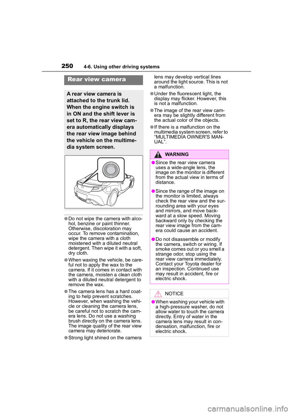
Rear view camera
A rear view camera is
attached to the trunk lid.
When the engine switch is
in ON and the shift lever is
set to R, the rear view cam-
era automatically displays
the rear view image behind
the vehicle on the multime-
dia system screen.
WARNING
●Since the rear view camera
uses a wide-angle lens, the
image on the monitor is different
from the actual view in terms of
distance.
●Since the range of the image on
the monitor is limited, always
check the rear view and the sur-
rounding area with your eyes
and mirrors, and move back-
ward at a slow speed. Moving
backward only by checking the
rear view image from the cam-
era could cause an accident.
●Do not disassemble or modify
the camera, switch or wiring. If
smoke comes out or you smell a
strange odor, stop using the
rear view camera immediately.
Contact your Toyota dealer for
an inspection. Continued use
may result in accident, fire or
electric shock.
NOTICE
●When washing your vehicle with
a high-pressure washer, do not
allow water to touch the camera
directly. Entry of water in the
camera lens may result in con-
densation, malfunction, fire or
electric shock.
Page 251 of 449
2514-6. Using other driving systems
4
Driving
When the shift lever is set to R,
the rear view camera automati-
cally displays the rear view
image from the vehicle. When
the lever is set to other posi-
tions, the image before setting
to R is displayed.
1Set the engine switch to ON.
2 Set the shift lever to R.
●The image of the rear view cam-
era is horizontally reversed as is
the case with the vehicle inside mirror or the outside mirror.
●When “Rear Camera Delay Con-
trol” is on, the r
ear view image
from the r ear view camera will be
displayed on the multimedia sys-
tem screen for a certain amount of
time after the shift lever is shifted
from R to another position. When
any of the following conditions are
met, the rear view image will be
canceled:
• The shift lever is shifted to P (vehi- cles with an automatic transmis-
sion)
• The vehicle speed becomes approximately 5 mph (8 km/h) or
more
• The parking brake is engaged
• 9 seconds have elapsed since the shift lever was shifted from R to
another position
To turn the function on and off, refer
to “MULTIMEDIA OWNER’S MAN-
UAL”.
●It may be difficult to see the image
of the rear view camera in the fol-
lowing cases. This is not a mal-
function of the camera.
• The vehicle is in a dark place (at night, in a tunnel, etc.).
• The vehicle is in an extremely hot or cold place.
• An object (such as raindrops,
snow, dirt, etc.) that disturbs the
view of the rear view camera
sticks to the lens of the camera.
• Strong light is shining directly on the camera lens ( occasionally,
there are vertical lines on the
screen).
The area from the rear end of
the bumper can be viewed.
Areas at both ends of the
bumper and areas just under the
bumper cannot be viewed.
NOTICE
●Since the camera is a precision
device, do not subject it to
strong impacts. Otherwise, mal-
function, fire or electric shock
may occur.
●If mud or snow sticks to or is fro-
zen on the camera, you must be
very careful when removing it.
Otherwise, damage to the cam-
era may cause a fire or electric
shock. Pour water or lukewarm
water over the camera to
remove mud and ice, and wipe
it with a soft, dry cloth.
●Do not put a flame close to the
camera or wirin g. Otherwise,
damage or fire may occur.
●When replacing the fuse, be
sure to use a fuse with the spec-
ified rating. Use of a fuse with a
different rating may result in a
malfunction.
●If you use the rear view camera
for a long time while the engine
is not operated, the battery may
become completely discharged.
How to use the rear view
camera
Viewing range on the
screen
Page 253 of 449
2534-6. Using other driving systems
4
Driving
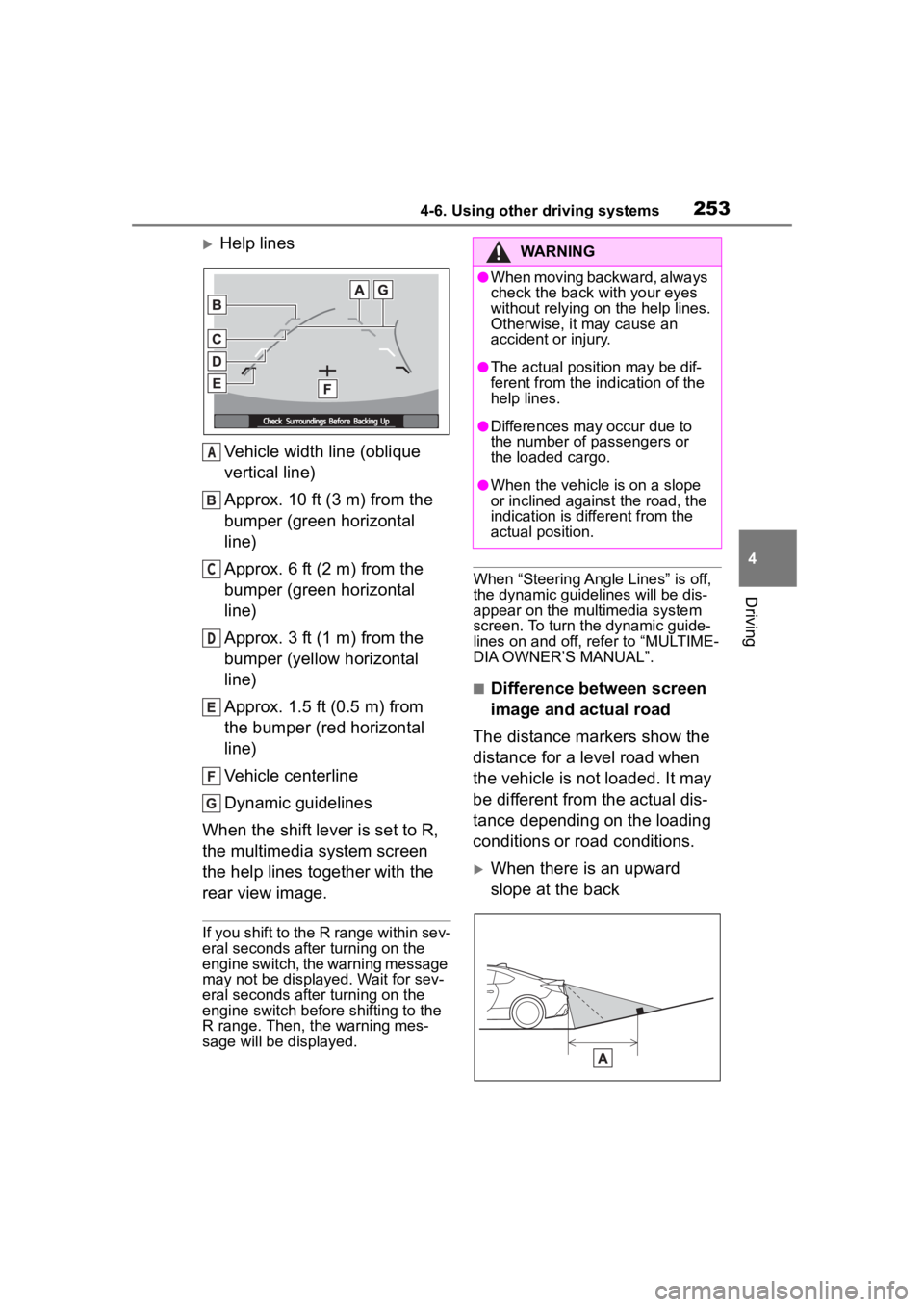
Help linesVehicle width line (oblique
vertical line)
Approx. 10 ft (3 m) from the
bumper (green horizontal
line)
Approx. 6 ft (2 m) from the
bumper (green horizontal
line)
Approx. 3 ft (1 m) from the
bumper (yellow horizontal
line)
Approx. 1.5 ft (0.5 m) from
the bumper (red horizontal
line)
Vehicle centerline
Dynamic guidelines
When the shift lever is set to R,
the multimedia system screen
the help lines together with the
rear view image.
If you shift to the R range within sev-
eral seconds after turning on the
engine switch, the warning message
may not be displayed. Wait for sev-
eral seconds after turning on the
engine switch before shifting to the
R range. Then, the warning mes-
sage will be displayed.
When “Steering Angle Lines” is off,
the dynamic guidelines will be dis-
appear on the multimedia system
screen. To turn the dynamic guide-
lines on and off, refer to “MULTIME-
DIA OWNER’S MANUAL”.
■Difference between screen
image and actual road
The distance markers show the
distance for a level road when
the vehicle is not loaded. It may
be different from the actual dis-
tance depending on the loading
conditions or road conditions.
When there is an upward
slope at the back
A
C
D
WARNING
●When moving backward, always
check the back with your eyes
without relying on the help lines.
Otherwise, it may cause an
accident or injury.
●The actual position may be dif-
ferent from the in dication of the
help lines.
●Differences may occur due to
the number of passengers or
the loaded cargo.
●When the vehicle is on a slope
or inclined against the road, the
indication is dif ferent from the
actual position.
Page 255 of 449
2554-6. Using other driving systems
4
Driving
●Conventional Cruise Control
enables you to maintain a con-
stant vehicle speed without hold-
ing your foot on the accelerator
pedal and it is operative when the
vehicle speed is 20 mph (30 km/h)
or more.
●Make sure the Conventional
Cruise Control system is turned
off when the Conventional Cruise
Control is not in use to avoid unin-
tentionally setting of the Conven-
tional Cruise Control.
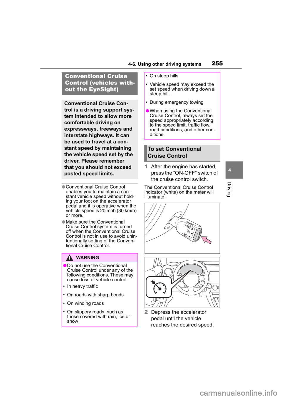
1After the engine has started,
press the “ON-OFF” switch of
the cruise control switch.
The Conventional Cruise Control
indicator (white) on the meter will
illuminate.
2Depress the accelerator
pedal until the vehicle
reaches the desired speed.
Conventional Cruise
Control (vehicles with-
out the EyeSight)
Conventional Cruise Con-
trol is a driving support sys-
tem intended to allow more
comfortable driving on
expressways, freeways and
interstate highways. It can
be used to travel at a con-
stant speed by maintaining
the vehicle speed set by the
driver. Please remember
that you should not exceed
posted speed limits.
WARNING
●Do not use the Conventional
Cruise Control under any of the
following conditions. These may
cause loss of vehicle control.
• In heavy traffic
• On roads with sharp bends
• On winding roads
• On slippery roads, such as those covered with rain, ice or
snow
• On steep hills
• Vehicle speed may exceed the set speed when d riving down a
steep hill.
• During emergency towing
●When using the Conventional
Cruise Control, always set the
speed appropriately according
to the speed limit, traffic flow,
road conditions, and other con-
ditions.
To set Conventional
Cruise Control
Page 257 of 449
2574-6. Using other driving systems
4
Driving
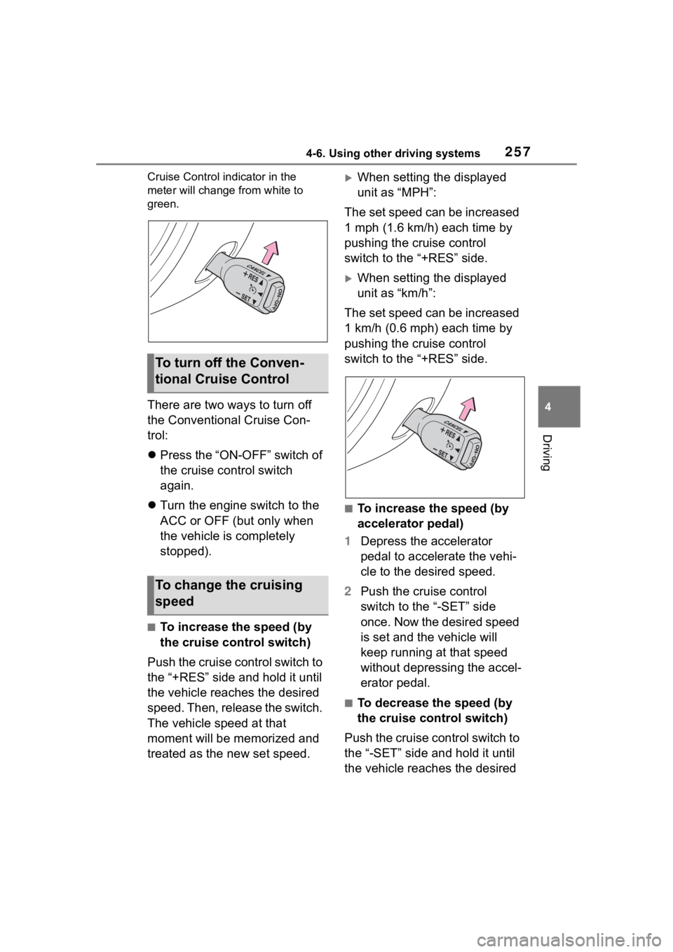
Cruise Control indicator in the
meter will change from white to
green.
There are two ways to turn off
the Conventional Cruise Con-
trol:
Press the “ON-OFF” switch of
the cruise control switch
again.
Turn the engine switch to the
ACC or OFF (but only when
the vehicle is completely
stopped).
■To increase the speed (by
the cruise control switch)
Push the cruise control switch to
the “+RES” side and hold it until
the vehicle reaches the desired
speed. Then, release the switch.
The vehicle speed at that
moment will be memorized and
treated as the new set speed.
When setting the displayed
unit as “MPH”:
The set speed can be increased
1 mph (1.6 km/h) each time by
pushing the cruise control
switch to the “+RES” side.
When setting the displayed
unit as “km/h”:
The set speed can be increased
1 km/h (0.6 mph) each time by
pushing the cruise control
switch to the “+RES” side.
■To increase the speed (by
accelerator pedal)
1 Depress the accelerator
pedal to accelerate the vehi-
cle to the desired speed.
2 Push the cruise control
switch to the “-SET” side
once. Now the desired speed
is set and the vehicle will
keep running at that speed
without depressing the accel-
erator pedal.
■To decrease the speed (by
the cruise control switch)
Push the cruise control switch to
the “-SET” side and hold it until
the vehicle reaches the desired
To turn off the Conven-
tional Cruise Control
To change the cruising
speed