2023 HYUNDAI IONIQ 5 cluster
[x] Cancel search: clusterPage 122 of 680

03
3-35
OHI038175L
The Pre-Tensioner Seat Belt System
consists mainly of the following
components. Their locations are shown
in the illustration above:
(1) SRS air bag warning light
(2) Retractor pre-tensioner
(3) SRS control module
NOTICE
The sensor that activates the SRS
control module is connected with the
pre–tensioner seat belts. The SRS air
bag warning light on the instrument
cluster will illuminate for approximately
3~6 seconds after the Start/Stop button is in the ON position, and then it should
turn off.
If the pre-tensioner is not working
properly, the warning light will
illuminate even if the SRS air bag is not
malfunctioning. If the warning light
does not illuminate, stays illuminated
or illuminates when the vehicle is being
driven, have the pre-tensioner seat
belts and/or SRS control module be
inspected by an authorized HYUNDAI dealer as soon as possible.
Information
• Pre-tensioner seat belts may be
activated in certain frontal or side
collisions or rollover situations (if
equipped with rollover sensor).
• When the pre-tensioner seat belts are activated, a loud noise may be heard
and fine dust, which may appear to be
smoke, may be visible in the passenger
compartment. These are normal
operating conditions and are not hazardous.
• Although it is non-toxic, the fine dust may cause skin irritation and should
not be inhaled for prolonged periods.
Wash all exposed skin areas thoroughly
after an accident in which the pre-
tensioner seat belts were activated.
Page 144 of 680
03
3-57
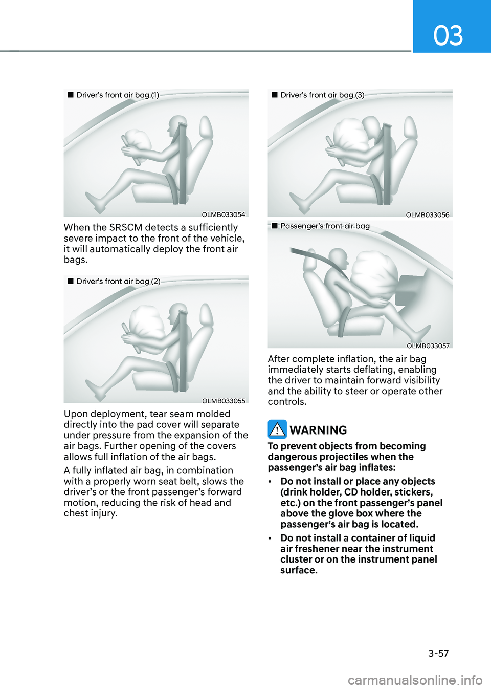
„„Driver’s front air bag (1)
OLMB033054
When the SRSCM detects a sufficiently
severe impact to the front of the vehicle,
it will automatically deploy the front air bags.
„„Driver’s front air bag (2)
OLMB033055
Upon deployment, tear seam molded
directly into the pad cover will separate
under pressure from the expansion of the
air bags. Further opening of the covers
allows full inflation of the air bags.
A fully inflated air bag, in combination
with a properly worn seat belt, slows the
driver’s or the front passenger’s forward
motion, reducing the risk of head and
chest injury.
„„Driver’s front air bag (3)
OLMB033056
„„Passenger’s front air bag
OLMB033057
After complete inflation, the air bag
immediately starts deflating, enabling
the driver to maintain forward visibility
and the ability to steer or operate other
controls.
WARNING
To prevent objects from becoming
dangerous projectiles when the
passenger’s air bag inflates: • Do not install or place any objects
(drink holder, CD holder, stickers,
etc.) on the front passenger’s panel
above the glove box where the
passenger’s air bag is located.
• Do not install a container of liquid
air freshener near the instrument
cluster or on the instrument panel
surface.
Page 159 of 680

4
4. Instrument Cluster
Instrument Cluster ............................................................................................ 4-4
Instrument Cluster Control .......................................................................................... 4-5
Instrument panel illumination ................................................................................... 4-5
Gauges and Meters ...................................................................................................... 4-5
Speedometer ............................................................................................................. 4-5
Power/Charge Gauge ................................................................................................. 4-6
State of Charge (SOC) Gauge for High Voltage Battery ...........................................4-6
Outside temperature gauge ...................................................................................... 4 -7
Odometer .................................................................................................................. 4-8
Distance to empty .................................................................................................... 4-8
Reduction Gear Shift Indicator ................................................................................... 4-9
Regenerative braking level indicator ....................................................................... 4-9
Warning and Indicator Lights ..................................................................................... 4-9
Ready indicator ......................................................................................................... 4-9
Service warning light ................................................................................................ 4-9
Power down indicator light ..................................................................................... 4-10
Charging indicator light ........................................................................................... 4-10
High voltage battery level warning light ................................................................4-10
Seat belt warning light ............................................................................................ 4-10
Air bag warning light ................................................................................................ 4-11
Regenerative brake warning light ............................................................................ 4-11
Parking brake & brake fluid warning light ...............................................................4-11
Anti-lock Brake System (ABS) warning light ..........................................................4-12
Electronic Brake Force Distribution (EBD) system warning light .........................4-12
Electric Power Steering (EPS) warning light ..........................................................4-13
Master warning light ................................................................................................ 4-13
Electronic Parking Brake (EPB) warning light ........................................................4-14
Low tire pressure warning light .............................................................................. 4-14
Forward safety warning light .................................................................................. 4-15
Lane safety indicator light ...................................................................................... 4-15
All Wheel Drive (AWD) warning light ...................................................................... 4-15
LED headlight warning light .................................................................................... 4-16
Icy road warning light .............................................................................................. 4-16
Electronic Stability Control (ESC) indicator light ....................................................4-17
Electronic Stability Control (ESC) OFF indicator light ............................................4-17
Immobilizer indicator light ....................................................................................... 4-17
Turn signal indicator light ........................................................................................ 4-18
High beam indicator light ....................................................................................... 4-18
Light ON indicator light ........................................................................................... 4-18
High Beam Assist indicator light (if equipped) ......................................................4-19
AUTO HOLD indicator light ..................................................................................... 4-19
Page 161 of 680
4
LCD Display ..................................................................................................... 4-29
LCD Display Control ................................................................................................... 4-29
View Modes ................................................................................................................ 4-29
Driving assist view .................................................................................................. 4-30
Turn By Turn (TBT) view .......................................................................................... 4-30
Utility view ................................................................................................................ 4-31
Accumulated info .................................................................................................... 4-31
Additional information display ................................................................................ 4-33
Vehicle Settings (infotainment system) ........................................................4-34
Setting Your Vehicle .................................................................................................. 4-34
4. Instrument Cluster
Page 162 of 680
4-4
Instrument Cluster
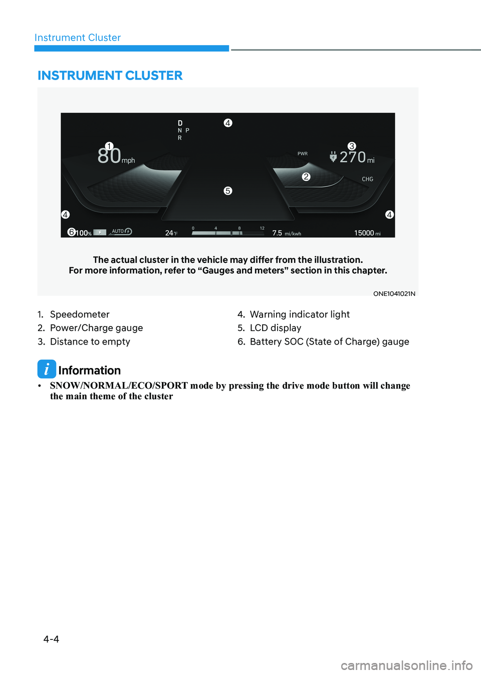
1. Speedometer
2. Power/Charge gauge
3. Distance to empty4.
Warning indicator light
5. LCD display
6. Battery SOC (State of Charge) gauge
Instrument cluster
The actual cluster in the vehicle may differ from the illustration.
For more information, refer to “Gauges and meters” section in this chapter.
ONE1041021N
Information
• SNOW/NORMAL/ECO/SPORT mode by pressing the drive mode button will change the main theme of the cluster
Page 163 of 680
04
4-5
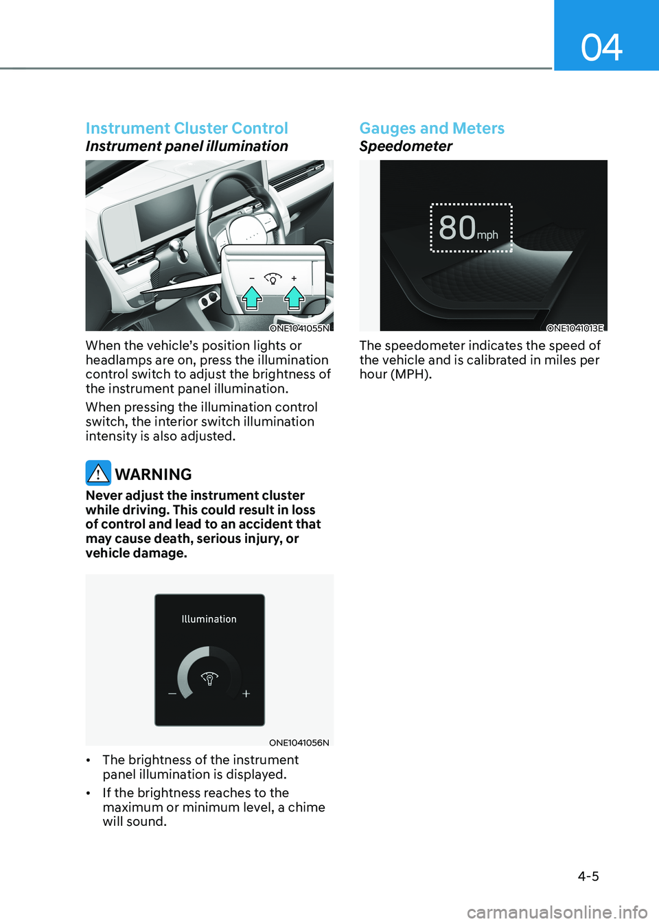
Instrument Cluster Control
Instrument panel illumination
ONE1041055N
When the vehicle’s position lights or
headlamps are on, press the illumination
control switch to adjust the brightness of
the instrument panel illumination.
When pressing the illumination control
switch, the interior switch illumination
intensity is also adjusted.
WARNING
Never adjust the instrument cluster
while driving. This could result in loss
of control and lead to an accident that
may cause death, serious injury, or
vehicle damage.
ONE1041056N
• The brightness of the instrument
panel illumination is displayed.
• If the brightness reaches to the
maximum or minimum level, a chime will sound.
Gauges and Meters
Speedometer
ONE1041013E
The speedometer indicates the speed of
the vehicle and is calibrated in miles per hour (MPH).
Page 164 of 680
Instrument Cluster
4-6
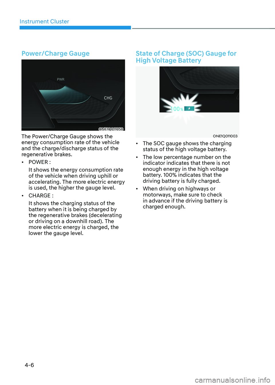
Power/Charge Gauge
ONE1Q011050
The Power/Charge Gauge shows the
energy consumption rate of the vehicle
and the charge/discharge status of the
regenerative brakes. • POWER :
It shows the energy consumption rate
of the vehicle when driving uphill or
accelerating. The more electric energy
is used, the higher the gauge level.
• CHARGE :
It shows the charging status of the
battery when it is being charged by
the regenerative brakes (decelerating
or driving on a downhill road). The
more electric energy is charged, the
lower the gauge level.
State of Charge (SOC) Gauge for
High Voltage Battery
ONE1Q011003
• The SOC gauge shows the charging
status of the high voltage battery.
• The low percentage number on the
indicator indicates that there is not
enough energy in the high voltage
battery. 100% indicates that the
driving battery is fully charged.
• When driving on highways or
motorways, make sure to check
in advance if the driving battery is
charged enough.
Page 165 of 680

04
4 -7
ONE1Q011011
When the remaining battery is lower than
10 % on the SOC gauge, the warning light (
) turns ON to alert you of the battery
level.
When the warning light (
) turns ON,
the vehicle can drive an additional 18 ~
25 miles (30 ~ 40 km) depending on the
driving speed, heater/air conditioner,
weather, driving style, and other factors.
Charging is required.
NOTICE
The output is limited as the remaining
battery is low.
When the Power Down Indicator Light
is on, the vehicle may be limited to
a certain speed, it may be difficult
to climb hills, or the vehicle may be
pushed back, so charge it immediately. Outside temperature gauge
ONE1041014N
This gauge indicates the current outside
air temperatures by 1°F (1°C).
Note that the temperature indicated
on the LCD display may not change
as quickly as the outside temperature
(there may be a slight delay before the
temperature changes.)
You can change the temperature
unit from the Settings menu in the
infotainment system screen. Select:
- General Settings → Unit → Temperature Unit → °C/°F
For detailed information, refer to the
separately supplied infotainment
system manual.
Both the temperature unit on the cluster
LCD display and climate control screen will change.