2023 HYUNDAI IONIQ 5 cluster
[x] Cancel search: clusterPage 585 of 680

08
8 -7
ONE1081004
ONE1081005L
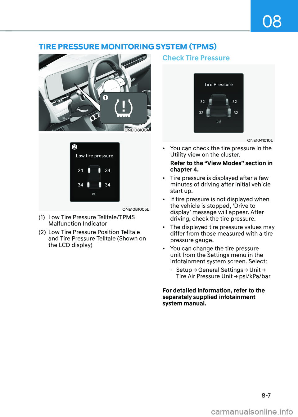
(1) Low Tire Pressure Telltale/TPMS Malfunction Indicator
(2) Low Tire Pressure Position Telltale and Tire Pressure Telltale (Shown on
the LCD display)
Check Tire Pressure
ONE1041010L
• You can check the tire pressure in the
Utility view on the cluster.
Refer to the “View Modes” section in
chapter 4.
• Tire pressure is displayed after a few
minutes of driving after initial vehicle
start up.
• If tire pressure is not displayed when
the vehicle is stopped, ‘Drive to
display’ message will appear. After
driving, check the tire pressure.
• The displayed tire pressure values may
differ from those measured with a tire
pressure gauge.
• You can change the tire pressure
unit from the Settings menu in the
infotainment system screen. Select:
- Setup → General Settings → Unit →
Tire Air Pressure Unit → psi/kPa/bar
For detailed information, refer to the
separately supplied infotainment
system manual.
tire pressure monitoring system (tpms)
Page 587 of 680

08
8-9
Low Tire Pressure
Warning Light
Low Tire Pressure Position and
Tire Pressure Telltale
ONE1081021L
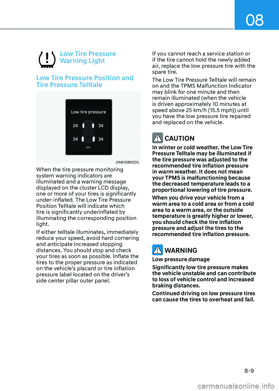
When the tire pressure monitoring
system warning indicators are
illuminated and a warning message
displayed on the cluster LCD display,
one or more of your tires is significantly
under-inflated. The Low Tire Pressure
Position Telltale will indicate which
tire is significantly underinflated by
illuminating the corresponding position
light.
If either telltale illuminates, immediately
reduce your speed, avoid hard cornering
and anticipate increased stopping
distances. You should stop and check
your tires as soon as possible. Inflate the
tires to the proper pressure as indicated
on the vehicle’s placard or tire inflation
pressure label located on the driver’s
side center pillar outer panel. If you cannot reach a service station or
if the tire cannot hold the newly added
air, replace the low pressure tire with the
spare tire.
The Low Tire Pressure Telltale will remain
on and the TPMS Malfunction Indicator
may blink for one minute and then
remain illuminated (when the vehicle
is driven approximately 10 minutes at
speed above 25 km/h (15.5 mph)) until
you have the low pressure tire repaired
and replaced on the vehicle.
CAUTION
In winter or cold weather, the Low Tire
Pressure Telltale may be illuminated if
the tire pressure was adjusted to the
recommended tire inflation pressure
in warm weather. It does not mean
your TPMS is malfunctioning because
the decreased temperature leads to a
proportional lowering of tire pressure.
When you drive your vehicle from a
warm area to a cold area or from a cold
area to a warm area, or the outside
temperature is greatly higher or lower,
you should check the tire inflation
pressure and adjust the tires to the
recommended tire inflation pressure.
WARNING
Low pressure damage
Significantly low tire pressure makes
the vehicle unstable and can contribute
to loss of vehicle control and increased
braking distances.
Continued driving on low pressure tires
can cause the tires to overheat and fail.
Page 640 of 680

09
9-39
Instrument panel fuse panel
Fuse NameFuse Rating Circuit Protected
Child Lock 15A Child Lock Relay, Child Unlock Relay
A/BAG IND 7.5A Overhead Console
MEMORY2 10A
Head-Up Display
STA RT 7.5A VCU, IBU
S/CHARGE2 20A
SDC
MIRR HTR 10ADriver Outside Mirror Unit, Passenger Outside Mirror Unit
T/GATE 15A Liftgate Release Relay
EPCU2 10A
Rear Inverter
MODULE3 7.5AMultifunction Switch, IBU, Stop Lamp Switch, Driver
Door Module
CLUSTER 7.5A Head-Up Display, Instrument Cluster
IG3 8 10AV2L Unit, ICCU, VCMS, Rear Electronic Oil Pump, CDM
IG3 7 10AIncar Temperature Sensor, A/V & Navigation
Head Unit, A/C PTC Heater, A/C Control Module,
Instrument Cluster, High-Voltage Charging Lamp
IAU 10A
IAU, BLE UNIT
S/CHARGER/VISION ROOF 20A
SDC, Vison Roof
AFCU 10A
AFCU, Driver/Passenger Door Outside Handle
Page 642 of 680

09
9-41
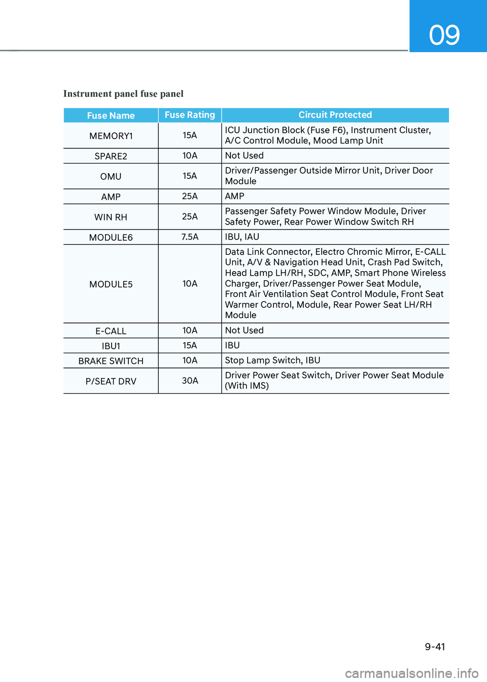
Instrument panel fuse panel
Fuse NameFuse Rating Circuit Protected
MEMORY1 15AICU Junction Block (Fuse F6), Instrument Cluster,
A/C Control Module, Mood Lamp Unit
SPARE2 10A
Not Used
OMU 15ADriver/Passenger Outside Mirror Unit, Driver Door
Module
AMP 25A AMP
WIN RH 25APassenger Safety Power Window Module, Driver
Safety Power, Rear Power Window Switch RH
MODULE6 7.5A IBU, IAU
MODULE5 10AData Link Connector, Electro Chromic Mirror, E-CALL
Unit, A/V & Navigation Head Unit, Crash Pad Switch,
Head Lamp LH/RH, SDC, AMP, Smart Phone Wireless
Charger, Driver/Passenger Power Seat Module,
Front Air Ventilation Seat Control Module, Front Seat
Warmer Control, Module, Rear Power Seat LH/RH
Module
E-CALL 10A
Not Used
IBU1 15A IBU
BRAKE SWITCH 10A
Stop Lamp Switch, IBU
P/SEAT DRV 30ADriver Power Seat Switch, Driver Power Seat Module (With IMS)
Page 673 of 680

Index
I-8
Instrument cluster .................................................................................................. 4-4
Gauges and Meters ............................................................................................. 4-5
Instrument Cluster Control ................................................................................. 4-5
LCD Display Messages .................................................................................... 4-19
Power/Charge Gauge .......................................................................................... 4-6
Reduction Gear Shift Indicator .......................................................................... 4-9
State of Charge (SOC) Gauge for High Voltage Battery ....................................4-6
Warning and Indicator Lights ............................................................................. 4-9
Instrument Panel Overview (I) .............................................................................. 2-5
Instrument Panel Overview (II) ............................................................................. 2-6
Integrated Memory System.................................................................................. 5-40
Recalling Memory Positions ............................................................................ 5-40
Resetting the System ........................................................................................ 5-41
Seat Easy Access .............................................................................................. 5-42
Storing Memory Positions ................................................................................ 5-40
Intelligent Speed Limit Assist (ISLA) ................................................................. 7-56
Intelligent Speed Limit Assist Malfunction and Limitations ...........................7-59
Intelligent Speed Limit Assist Operation .........................................................7-57
Intelligent Speed Limit Assist Settings ............................................................7-56
Interior Features ................................................................................................. 5-121
Cargo Security Screen .................................................................................... 5-130
Clock .............................................................................................................. 5-127
Cluster Fascia Side Panel ............................................................................... 5-127
Coat Hook ...................................................................................................... 5-128
Cup Holder ..................................................................................................... 5-121
Floor Mat Anchor(s) ....................................................................................... 5-128
Luggage Net Holder ....................................................................................... 5-129
Power Outlet ................................................................................................... 5-122
Rear Side Window Sunshades ........................................................................ 5-129
Sunvisor .......................................................................................................... 5-122
USB Charger .................................................................................................. 5-123
Vehicle to Load (V2L) ................................................................................... 5-127
Wireless Smart Phone Charging System ........................................................5-124
Interior Overview .................................................................................................. 2-4 J
Jump Starting (12V battery) .................................................................................. 8-4
Page 675 of 680

Index
I-10
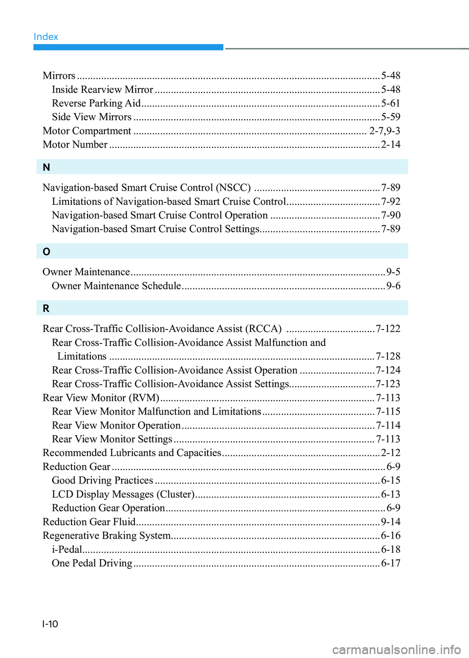
Mirrors ................................................................................................................. 5-48
Inside Rearview Mirror .................................................................................... 5-48
Reverse Parking Aid ......................................................................................... 5-61
Side View Mirrors ............................................................................................ 5-59
Motor Compartment ....................................................................................... 2-7,9-3
Motor Number ..................................................................................................... 2-14
N Navigation-based Smart Cruise Control (NSCC) ...............................................7-89
Limitations of Navigation-based Smart Cruise Control ...................................7-92
Navigation-based Smart Cruise Control Operation .........................................7-90
Navigation-based Smart Cruise Control Settings .............................................7-89
OOwner Maintenance ............................................................................................... 9-5
Owner Maintenance Schedule ............................................................................ 9-6
R
Rear Cross-Traffic Collision-Avoidance Assist (RCCA) .................................7-122
Rear Cross-Traffic Collision-Avoidance Assist Malfunction and
Limitations ................................................................................................... 7-128
Rear Cross-Traffic Collision-Avoidance Assist Operation ............................7-124
Rear Cross-Traffic Collision-Avoidance Assist Settings................................ 7-123
Rear View Monitor (RVM) ................................................................................ 7-113
Rear View Monitor Malfunction and Limitations ..........................................7-115
Rear View Monitor Operation ........................................................................ 7-114
Rear View Monitor Settings ........................................................................... 7-113
Recommended Lubricants and Capacities ...........................................................2-12
Reduction Gear ...................................................................................................... 6-9
Good Driving Practices .................................................................................... 6-15
LCD Display Messages (Cluster) ..................................................................... 6-13
Reduction Gear Operation .................................................................................. 6-9
Reduction Gear Fluid ........................................................................................... 9-14
Regenerative Braking System.............................................................................. 6-16 i-Pedal ............................................................................................................... 6-18
One Pedal Driving ............................................................................................ 6-17