2023 FORD EXPEDITION lock
[x] Cancel search: lockPage 425 of 658

If you replace the battery make sure itmatches the electrical requirements ofyour vehicle.
If you disconnect or replace the batteryand your vehicle has an automatictransmission, it must relearn its adaptivestrategy. Because of this, the transmissionmay shift firmly when first driven. This isnormal operation while the transmissionfully updates its operation to optimumshift feel.
Battery Sensor Reset
When you install a new battery, reset thebattery sensor by doing the following:
1.Switch the ignition on, and leave theengine off.
Note:Complete Steps 2 and 3 within 10seconds.
2.Flash the high beam headlamps fivetimes, ending with the high beams off.
3.Press and release the brake pedal threetimes.
The battery warning lamp flashes threetimes to confirm that the reset issuccessful.
Battery Management System (If
Equipped)
The system monitors battery conditionsand takes actions to extend battery life. Ifexcessive battery drain is detected, thesystem temporarily disables someelectrical systems to protect the battery.
Systems included are:
•Heated rear window.
•Heated seats.
•Climate control.
•Heated steering wheel.
•Audio unit.
•Navigation system.
A message may appear in the informationdisplay to alert you that battery protectionactions are active. This message is only fornotification that an action is taking place,and not intended to indicate an electricalproblem or that the battery requiresreplacement.
After battery replacement, or in somecases after charging the battery with anexternal charger, the battery managementsystem requires eight hours of vehicle sleeptime to relearn the battery state of charge.During this time, your vehicle must remainfully locked with the ignition switched off.
Note:Prior to relearning the battery stateof charge, the battery management systemmay temporarily disable some electricalsystems.
Electrical Accessory Installation
To make sure the battery managementsystem works correctly, do not connect anelectrical device ground connectiondirectly to the battery negative post. Thiscan cause inaccurate measurements ofthe battery condition and potentialincorrect system operation.
Note:If you add electrical accessories orcomponents to the vehicle, it may adverselyaffect battery performance and durability.This may also affect the performance ofother electrical systems in the vehicle.
Remove and Reinstall the Battery
Install a battery approved for use by ourspecifications. See Capacities andSpecifications (page 463).
To disconnect or remove the battery, dothe following:
1.Apply the parking brake and switch theignition off.
2.Switch all electrical equipment off, forexample lights and radio.
421
2023 Expedition (TB8) Canada/United States of America, enUSA, Edition date: 202207, DOMMaintenance
Page 426 of 658
3.Wait a minimum of two minutes beforedisconnecting the battery.
Note:The engine management system hasa power hold function and remains poweredfor a period of time after you switch theignition off. This is to allow the system tostore diagnostic and adaptive tables.Disconnecting the battery without waitingcan cause damage not covered by thevehicle warranty.
4.Disconnect the negative battery cableterminal.
5.Disconnect the positive battery cableterminal.
6.Remove the battery securing clamp.
7.Remove the battery.
8.To install, reverse the removalprocedure.
Note:Before reconnecting the battery,make sure the ignition remains switched off.
Note:Make sure to fully tighten the batterycables.
If you disconnect or replace the vehiclebattery, you must reset the followingfeatures:
•Window bounce-back. See Lockingthe Rear Window Controls (page 128).
•Clock Settings.
•Pre-set radio stations.
Battery Disposal
Make sure that you dispose ofold batteries in anenvironmentally friendly way.Seek advice from your local authorityabout recycling old batteries.
ADJUSTING THE HEADLAMPS
Vertical Aim Adjustment
The headlamps on your vehicle areproperly aimed at the assembly plant. Ifyour vehicle has been in an accident,contact an authorized dealer to check andrealign your headlamps.
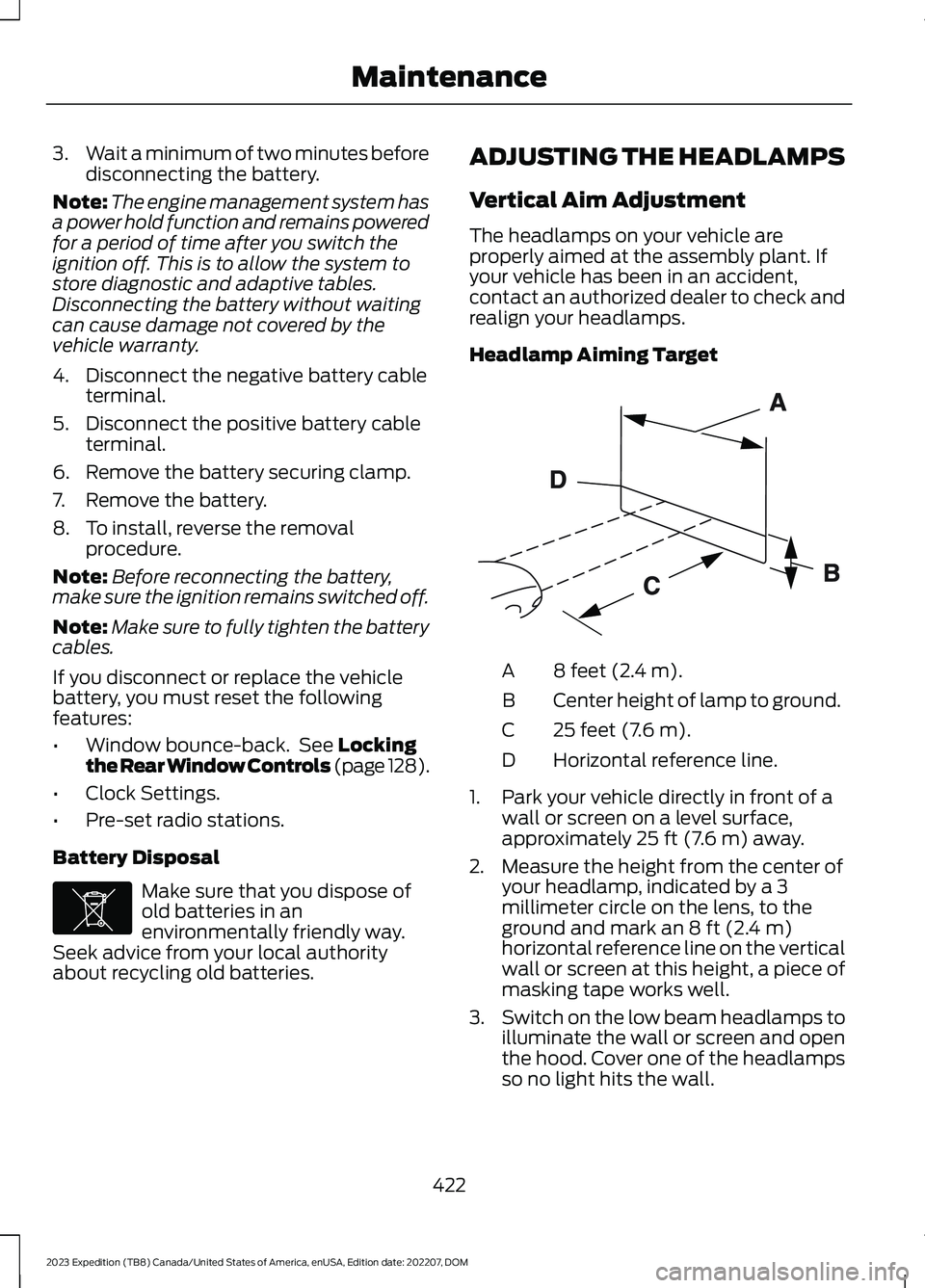
Headlamp Aiming Target
8 feet (2.4 m).A
Center height of lamp to ground.B
25 feet (7.6 m).C
Horizontal reference line.D
1.Park your vehicle directly in front of awall or screen on a level surface,approximately 25 ft (7.6 m) away.
2.Measure the height from the center ofyour headlamp, indicated by a 3millimeter circle on the lens, to theground and mark an 8 ft (2.4 m)horizontal reference line on the verticalwall or screen at this height, a piece ofmasking tape works well.
3.Switch on the low beam headlamps toilluminate the wall or screen and openthe hood. Cover one of the headlampsso no light hits the wall.
422
2023 Expedition (TB8) Canada/United States of America, enUSA, Edition date: 202207, DOMMaintenanceE107998 E142592
Page 427 of 658
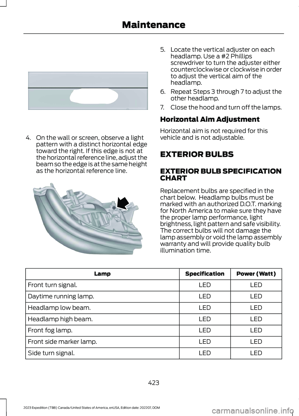
4.On the wall or screen, observe a lightpattern with a distinct horizontal edgetoward the right. If this edge is not atthe horizontal reference line, adjust thebeam so the edge is at the same heightas the horizontal reference line.
5.Locate the vertical adjuster on eachheadlamp. Use a #2 Phillipsscrewdriver to turn the adjuster eithercounterclockwise or clockwise in orderto adjust the vertical aim of theheadlamp.
6.Repeat Steps 3 through 7 to adjust theother headlamp.
7.Close the hood and turn off the lamps.
Horizontal Aim Adjustment
Horizontal aim is not required for thisvehicle and is not adjustable.
EXTERIOR BULBS
EXTERIOR BULB SPECIFICATIONCHART
Replacement bulbs are specified in thechart below. Headlamp bulbs must bemarked with an authorized D.O.T. markingfor North America to make sure they havethe proper lamp performance, lightbrightness, light pattern and safe visibility.The correct bulbs will not damage thelamp assembly or void the lamp assemblywarranty and will provide quality bulbillumination time.
Power (Watt)SpecificationLamp
LEDLEDFront turn signal.
LEDLEDDaytime running lamp.
LEDLEDHeadlamp low beam.
LEDLEDHeadlamp high beam.
LEDLEDFront fog lamp.
LEDLEDFront side marker lamp.
LEDLEDSide turn signal.
423
2023 Expedition (TB8) Canada/United States of America, enUSA, Edition date: 202207, DOMMaintenanceE167358 E163806
Page 429 of 658
REMOVING A REAR LAMPASSEMBLY
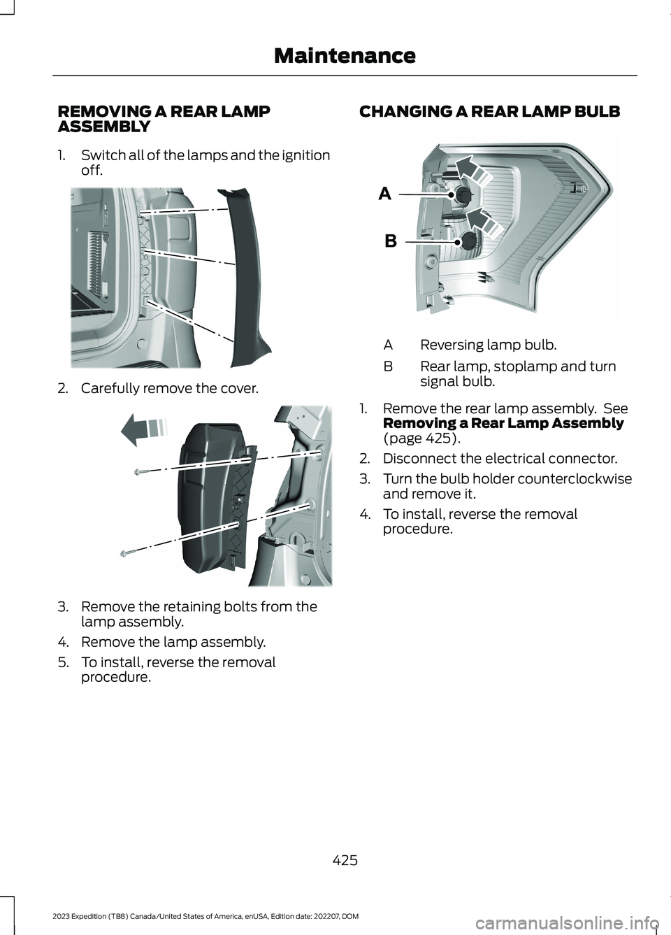
1.Switch all of the lamps and the ignitionoff.
2.Carefully remove the cover.
3.Remove the retaining bolts from thelamp assembly.
4.Remove the lamp assembly.
5.To install, reverse the removalprocedure.
CHANGING A REAR LAMP BULB
Reversing lamp bulb.A
Rear lamp, stoplamp and turnsignal bulb.B
1.Remove the rear lamp assembly. SeeRemoving a Rear Lamp Assembly(page 425).
2.Disconnect the electrical connector.
3.Turn the bulb holder counterclockwiseand remove it.
4.To install, reverse the removalprocedure.
425
2023 Expedition (TB8) Canada/United States of America, enUSA, Edition date: 202207, DOMMaintenanceE249669 E248886 E248889
Page 430 of 658
CHANGING A STOPLAMP BULB
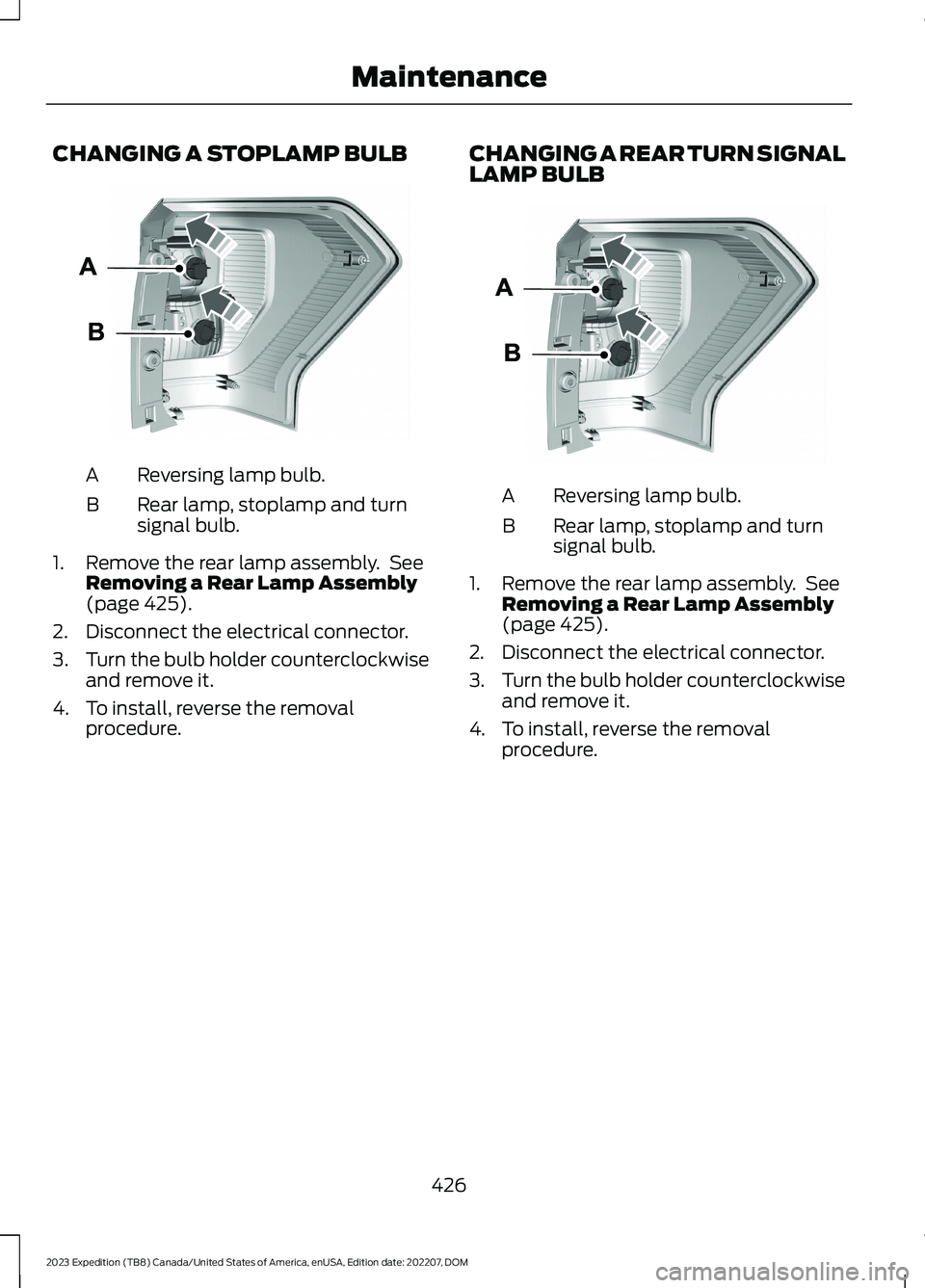
Reversing lamp bulb.A
Rear lamp, stoplamp and turnsignal bulb.B
1.Remove the rear lamp assembly. SeeRemoving a Rear Lamp Assembly(page 425).
2.Disconnect the electrical connector.
3.Turn the bulb holder counterclockwiseand remove it.
4.To install, reverse the removalprocedure.
CHANGING A REAR TURN SIGNALLAMP BULB
Reversing lamp bulb.A
Rear lamp, stoplamp and turnsignal bulb.B
1.Remove the rear lamp assembly. SeeRemoving a Rear Lamp Assembly(page 425).
2.Disconnect the electrical connector.
3.Turn the bulb holder counterclockwiseand remove it.
4.To install, reverse the removalprocedure.
426
2023 Expedition (TB8) Canada/United States of America, enUSA, Edition date: 202207, DOMMaintenanceE248889 E248889
Page 431 of 658
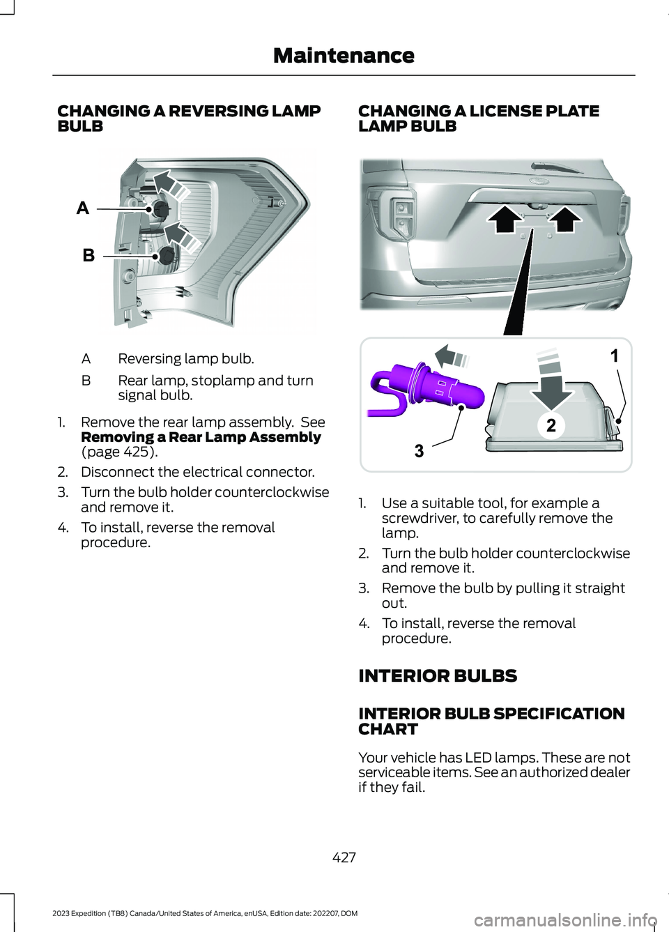
CHANGING A REVERSING LAMPBULB
Reversing lamp bulb.A
Rear lamp, stoplamp and turnsignal bulb.B
1.Remove the rear lamp assembly. SeeRemoving a Rear Lamp Assembly(page 425).
2.Disconnect the electrical connector.
3.Turn the bulb holder counterclockwiseand remove it.
4.To install, reverse the removalprocedure.
CHANGING A LICENSE PLATELAMP BULB
1.Use a suitable tool, for example ascrewdriver, to carefully remove thelamp.
2.Turn the bulb holder counterclockwiseand remove it.
3.Remove the bulb by pulling it straightout.
4.To install, reverse the removalprocedure.
INTERIOR BULBS
INTERIOR BULB SPECIFICATIONCHART
Your vehicle has LED lamps. These are notserviceable items. See an authorized dealerif they fail.
427
2023 Expedition (TB8) Canada/United States of America, enUSA, Edition date: 202207, DOMMaintenanceE248889 ABA12203AAE292276
Page 461 of 658

Drive cautiously when using a full-sizedissimilar spare wheel and tire assemblyand seek service as soon as possible.
Location of the Spare Tire andTools
The spare tire is located under the vehicle,just forward of the rear bumper. The jack,swivel wrench and lug wrench are in thefollowing locations:
LocationItem
Under the vehicle, just forward of the rearbumperSpare tire
Under the access panel located in the floorcompartment behind the rear seatJack and tool kit bag
Tire Change Procedure
WARNING: Only use replacementtires and wheels that are the same size,load index, speed rating, and type asthose originally provided for your vehicle.The recommended tire and wheel sizescan be found on the Tire Label on thedriver side door frame or the edge of thedriver door. If this information is notfound in those locations, or for additionaloptions, contact your authorized dealer.Use of any tire or wheel notrecommended, could affect the safetyand performance of your vehicle, whichcould result in an increased risk of lossof vehicle control, vehicle rollover,personal injury and death.
WARNING: To help prevent yourvehicle from moving when changing awheel, shift the transmission into park(P), set the parking brake and use anappropriate block or wheel chock tosecure the wheel diagonally opposite tothe wheel being changed. For example,when changing the front left wheel,place an appropriate block or wheelchock on the right rear wheel.
WARNING: Only use the jackprovided as original equipment with yourvehicle.
WARNING: Switch off the runningboards before jacking or placing anyobject under your vehicle. Never placeyour hand between the extended runningboard and your vehicle. A moving runningboard may cause injury.
WARNING: Only use the sparewheel carrier to stow wheels providedwith your vehicle.
WARNING: Ensure screwthread isadequately lubricated before use.
WARNING: Switch the ignition offand apply the parking brake. If yourvehicle has a manual transmission, shiftinto first or reverse gear. If your vehiclehas an automatic transmission, shift intopark (P).
WARNING: Only use the specifiedjacking points. If you use any otherlocations you could damage vehiclecomponents, such as brake lines.
457
2023 Expedition (TB8) Canada/United States of America, enUSA, Edition date: 202207, DOMChanging a Road Wheel
Page 462 of 658
WARNING: Do not attempt tochange a tire on the side of the vehicleclose to moving traffic. Pull far enoughoff the road to not obstruct the flow oftraffic and avoid the danger of being hitwhen operating the jack or changing thewheel.
1.Park the vehicle on firm, level groundand activate the hazard flashers.
2.Apply the parking brake, place thetransmission in park (P) and switch theignition off.
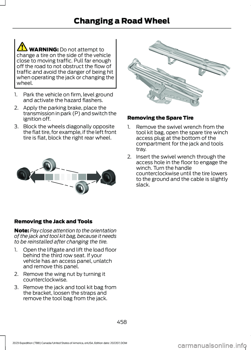
3.Block the wheels diagonally oppositethe flat tire, for example, if the left fronttire is flat, block the right rear wheel.
Removing the Jack and Tools
Note:Pay close attention to the orientationof the jack and tool kit bag, because it needsto be reinstalled after changing the tire.
1.Open the liftgate and lift the load floorbehind the third row seat. If yourvehicle has an access panel, unlatchand remove this panel.
2.Remove the wing nut by turning itcounterclockwise.
3.Remove the jack and tool kit bag fromthe bracket, loosen the straps andremove the tool bag from the jack.
Removing the Spare Tire
1.Remove the swivel wrench from thetool kit bag, open the spare tire winchaccess plug at the bottom of thecompartment for the jack and toolstray.
2.Insert the swivel wrench through theaccess hole in the floor to engage thewinch. Turn the handlecounterclockwise until the tire lowersto the ground and the cable is slightlyslack.
458
2023 Expedition (TB8) Canada/United States of America, enUSA, Edition date: 202207, DOMChanging a Road WheelE175447 E252435