Page 137 of 268

(Continued)
TRAILER AND TONGUE WEIGHT
Never exceed the maximum tongue weight
stamped on your fascia/bumper or trailer hitch.
Weight Distribution
Consider the following items when c")
135
(Continued)
(Continued)
TRAILER AND TONGUE WEIGHT
Never exceed the maximum tongue weight
stamped on your fascia/bumper or trailer hitch.
Weight Distribution
Consider the following items when computing the
weight on the rear axle of the vehicle:
The tongue weight of the trailer.
The weight of any other type of cargo or
equipment put in or on your vehicle.
The weight of the driver and all passengers.
NOTE:
Remember that everything put into or on the
trailer adds to the load on your vehicle. Also, addi -
tional factory-installed options or dealer-installed
options must be considered as part of the total
load on your vehicle. Refer to the “Tire And
Loading Information” placard for the maximum
combined weight of occupants and cargo for
your vehicle.
TOWING REQUIREMENTS
To promote proper break-in of your new vehicle
drivetrain components, the following guidelines
are recommended:
WARNING!
Always load a trailer with 60% of the weight in
the front of the trailer. This places 10% of the
GTW on the tow hitch of your vehicle. Loads
balanced over the wheels or heavier in the
rear can cause the trailer to sway severely side
to side which will cause loss of control of the
vehicle and trailer. Failure to load trailers
heavier in front is the cause of many
trailer collisions.
WARNING!
Improper towing can lead to a collision. Follow
these guidelines to make your trailer towing as
safe as possible:
Make certain that the load is secured in the
trailer and that it will not shift during travel.
When trailering cargo that is not fully
secured, dynamic load shifts can occur that
may be difficult for the driver to control. You
could lose control of your vehicle and have a
collision.
When hauling cargo, or towing a trailer, do
not overload your vehicle or trailer.
Overloading can cause a loss of control, poor
performance, or damage to brakes, axle,
engine, transmission, steering, suspension,
chassis structure, or tires.
Safety chains must always be used between
your vehicle and trailer. Always connect the
chains to the frame or hook retainers of the
vehicle hitch. Cross the chains under the
trailer tongue and allow enough slack for
turning corners.
Vehicles with trailers should not be parked
on a grade. When parking, apply the parking
brake on the tow vehicle. Put the tow vehicle
transmission in PARK. Always block or
"chock" the trailer wheels.
GCWR must not be exceeded.
Total weight must be distributed between
the tow vehicle and the trailer such that the
following four ratings are not exceeded:
• GVWR
• GTW
• GAWR
• Tongue weight rating for the trailer hitch
utilized.
CAUTION!
Do not tow a trailer at all during the first
500 miles (805 km) the new vehicle is
driven. The engine, axle or other parts could
be damaged.
WARNING!
23_GU_OM_EN_USC_t.book Page 135
Page 138 of 268

when towing while using a f")
STARTING AND OPERATING
136
Towing Requirements — Tires
Do not attempt to tow a trailer while using a
compact spare tire.
Do not drive more than 50 mph (80 km/h)
when towing while using a full size spare tire.
Proper tire inflation pressures are essential to
the safe and satisfactory operation of your
vehicle.
Check the trailer tires for proper tire inflation
pressures before trailer usage.
Check for signs of tire wear or visible tire
damage before towing a trailer.
Replacing tires with a higher load carrying
capacity will not increase the vehicle's GVWR
and GAWR limits.
For proper tire inflation procedures
Ú
page 224.
Towing Requirements — Trailer Brakes
Do not interconnect the hydraulic brake
system or vacuum system of your vehicle with
that of the trailer. This could cause inadequate
braking and possible personal injury.
An electronically actuated trailer brake
controller is required when towing a trailer with
electronically actuated brakes. When towing a
trailer equipped with a hydraulic surge
actuated brake system, an electronic brake
controller is not required.
Trailer brakes are recommended for trailers
over 1,000 lb (453 kg) and required for trailers
in excess of 2,000 lb (907 kg).
Towing Requirements — Trailer Lights
And Wiring
Whenever you pull a trailer, regardless of the
trailer size, stoplights and turn signals on the
trailer are required for motoring safety.
The Trailer Tow Package may include a four- and
seven-pin wiring harness. Use a factory approved
trailer harness and connector.
NOTE:
Do not cut or splice wiring into the vehicle’s wiring
harness.
The electrical connections are all complete to the
vehicle but you must mate the harness to a trailer
connector. Refer to the following illustrations.
NOTE:
Disconnect trailer wiring connector from the
vehicle before launching a boat (or any other
device plugged into vehicle’s electrical
connect) into water.
Be sure to reconnect once clear from
water area.
Then, during the first 500 miles (805 km)
that a trailer is towed, do not drive over
50 mph (80 km/h) and do not make starts
at full throttle. This helps the engine and
other parts of the vehicle wear in at the
heavier loads.
CAUTION!
WARNING!
Do not connect trailer brakes to your
vehicle's hydraulic brake lines. It can
overload your brake system and cause it to
fail. You might not have brakes when you
need them and could have an accident.
Towing any trailer will increase your stopping
distance. When towing, you should allow for
additional space between your vehicle and
the vehicle in front of you. Failure to do so
could result in an accident.
CAUTION!
If the trailer weighs more than 1,000 lb
(453 kg) loaded, it should have its own brakes
and they should be of adequate capacity.
Failure to do this could lead to accelerated
brake lining wear, higher brake pedal effort,
and longer stopping distances.
23_GU_OM_EN_USC_t.book Page 136
Page 139 of 268

137
Four-Pin Connector
Seven-Pin Connector
TOWING TIPS
Before setting out on a trip, practice turning,
stopping, and backing up the trailer in an area
located away from heavy traffic.
Automatic Transmission
Select the DRIVE range when towing. The
transmission controls include a drive strategy to
avoid frequent shifting when towing. However, if
frequent shifting does occur while in DRIVE, you
can use the AutoStick shift control to manually
select a lower gear.
NOTE:
Using a lower gear while operating the vehicle
under heavy loading conditions will improve
performance and extend transmission life by
reducing excessive shifting and heat buildup. This
action will also provide better engine braking.
Cruise Control — If Equipped
Do not use on hilly terrain or with heavy loads.
When using the Cruise Control, if you
experience speed drops greater than 10 mph
(16 km/h), disengage until you can get back to
cruising speed.
Use Cruise Control in flat terrain and with light
loads to maximize fuel efficiency.
INSTALLING THE RECEIVER
To properly install the receiver, see the following
directions:
1. Retrieve the receiver from the luggage compartment.
2. Push the receiver into the trailer hitch, and secure by inserting the locking pin into the
trailer hitch.
3. Insert the safety split ring into the hole on the locking pin.
NOTE:
Ensure that the locking pin is removed from the
trailer hitch before installing the receiver.
Trailer Hitch And Receiver
1 — Ground
2 — Park
3 — Left Stop/Turn
4 — Right Stop/Turn
1 — Backup Lamps
2 — Running Lamps
3 — Left Stop/Turn
4 — Ground
5 — Battery
6 — Right Stop/Turn
7 — Electric Brakes
1 – Receiver
2 – Locking Pin
3 – Safety Split Ring
A – Trailer Hitch
23_GU_OM_EN_USC_t.book Page 137
Page 140 of 268

STARTING AND OPERATING
138
CONNECTING THE ELECTRICAL SYSTEM
To connect the trailer’s electrical system, see the
following directions:
1. Remove the socket protective cover.
2. Completely insert the plug into the socket.Electrical Tow Connector
REMOVING THE RECEIVER
When the receiver is no longer needed,
disconnect the electrical connections and
remove it from its position using the following
directions:
1. Remove the safety split ring from thelocking pin.
2. Pull the locking pin out of the trailer hitch.
3. Remove the receiver from the trailer hitch.
SUGGESTIONS FOR
DRIVING
SAVING FUEL
The following suggestions may help you save fuel
and lower the amount of harmful emissions
released into the atmosphere.
Vehicle Maintenance
Checks and operations should be carried out in
accordance with the Maintenance Plan
Ú
page 199. Tires
Check the tire pressures at least once every four
weeks: if the pressure is too low, consumption
levels increase as resistance to rolling is higher.
NOTE:
Tire pressure that is too high can cause prema
-
ture tire wear, reduced control, etc.
Unnecessary Loads
Do not travel with an overloaded liftgate. The
weight of the vehicle and its arrangement greatly
affect fuel consumption and stability.
Electric Devices
Use electrical systems only for the amount of
time needed. The rear window defroster,
additional headlights, windshield wipers and
heater blower fan require a considerable amount
of energy; increasing the current uptake
increases fuel consumption (by up to +25% when
city driving).
Climate Control System
Using the climate control system will increase
consumption: use standard ventilation when the
temperature outside permits.
Devices For Aerodynamic Control
The use of non-certified devices for aerodynamic
control may adversely affect air drag and
consumption levels.
Pin
NumberFunction
1 Lights ground (Lights GND)
2 Position light, side marker
lights, and license plate light
3 Left turn signal and stop light
4 Right turn signal and stop light
23_GU_OM_EN_USC_t.book Page 138
Page 141 of 268

139
DRIVING STYLE
Starting
Do not warm up the engine at low or high revs
when the vehicle is stationary; this causes the
engine to warm up more slowly, thereby
increasing fuel consumption and emissions. It is
therefore advisable to drive off immediately,
slowly, avoiding high speeds: by doing this the
engine will warm up more quickly.
Unnecessary Actions
Avoid revving up when starting at traffic lights or
before stopping the engine. This action is
unnecessary and causes increased fuel
consumption and pollution.
Gear Selection
Use a high gear when traffic and road conditions
allow it. Using a low gear for faster acceleration
will increase fuel consumption. Improper use of a
high gear increases consumption, emissions and
engine wear.
Maximum Speed
Fuel consumption considerably increases as
speed increases. Maintain a constant speed,
avoiding unnecessary braking and acceleration,
which cost in terms of both fuel consumption and
emissions.
Acceleration
Accelerating violently severely affects
consumption and emissions: acceleration should
be gradual and should not exceed the maximum
torque.
CONDITIONS OF USE
Cold Starting
Short trips and frequent cold starts will not allow
the engine to reach optimum operating
temperature. This results in a significant increase
in consumption levels (from +15 to +30% in
city driving) and emissions.
Traffic And Road Conditions
High fuel consumption is caused by heavy traffic,
for instance when traveling in traffic with frequent
use of low gears or in cities with many traffic
lights. Winding mountain roads and rough road
surfaces also adversely affect consumption.
Stops In Traffic
During prolonged stops (e.g. railway crossings),
turn off the engine.
PERFORMANCE — QUADRIFOGLIO
This vehicle is equipped with an engine capable
of delivering exceptionally fast acceleration and
speed:
Peak power: 505 HP at 6,500 RPM.
Peak torque: 443 ft-lb at 2,500–5,000 RPM.
Top speed: 176 mph (283 km/h).
Acceleration from 0 to 60 mph (0 to 100 km/h):
3.6 seconds.
For safe driving, it is essential, particularly during
the first days of use, to get to know the car by
driving carefully and gradually discovering its
performance.
Driving On Race Tracks
Before driving on a track using a racing style, it is
necessary to:
Attend a race track driving course.
Check the liquid levels in the engine
compartment
Ú
page 199.
Have the car inspected at an authorized
dealer.
Remember that the car was not designed to be
driven exclusively on the race track and that this
use increases stress and component wear.
NOTE:
Quadrifoglio front brakes are equipped with
Non-Asbestos Organic (NAO) type pads. These
pads are NOT suitable for high thermal loads
(for example track use).
23_GU_OM_EN_USC_t.book Page 139
Page 142 of 268

SAFETY
This very important section describes the safety
systems that your vehicle may be equipped with,
and provides instructions on how to use them
correctly.
ACTIVE SAFETY SYSTE")
140
(Continued)
SAFETY
This very important section describes the safety
systems that your vehicle may be equipped with,
and provides instructions on how to use them
correctly.
ACTIVE SAFETY SYSTEMS
The vehicle may be equipped with the following
active safety devices:
Anti-Lock Brake System (ABS)
Active Torque Vectoring (ATV) System
Dynamic Steering Torque (DST) System
Drive Train Control (DTC) System
Electronic Stability Control (ESC) System
Hill Descent Control (HDC) System
Hill Start Assist (HSA) System
Panic Brake Assist (PBA) System
Traction Control System (TCS)
For system operation, see the following pages.
ANTI-LOCK BRAKE SYSTEM (ABS)
An integral part of the braking system, the ABS
prevents one or more wheels from locking and
slipping in all road surface conditions, regardless
of the intensity of the braking action. The system
ensures that the vehicle can be controlled even
during emergency braking, allowing the driver to
optimize stopping distances.
The system intervenes during braking when the
wheels are about to lock, typically in emergency
braking or low-grip conditions where locking may
be more frequent. The system also improves control and stability of
the vehicle when braking on a surface where the
grip of the left and right wheels varies, such as in
a corner.
The Electronic Braking Force Distribution (EBD)
system works with the ABS, allowing the brake
force to be distributed between the front and rear
wheels.
System Intervention
The ABS equipped on this vehicle is provided with
the "Brake-By-Wire", Integrated Brake System
(IBS), function. With this system, the command
given by pressing the brake pedal is not
transmitted hydraulically, but electrically.
Therefore, the light pulsation that is felt on the
pedal with the traditional system is no longer
noticeable.
ACTIVE TORQUE VECTORING (ATV)
S
YSTEM — IF EQUIPPED
The dynamic drive control is used to optimize and
balance the drive torque between the wheels of
the same axles. The ATV system improves the grip
in turns, sending more drive torque to the
external wheel.
Given that, in a turn, the external wheels of the
car travel more than the internal ones and
therefore turn faster, sending a higher thrust to
the external rear wheel allows for the car to be
more stable and to not suffer an "understeer"
condition. Understeer occurs when the vehicle is
turning less than appropriate for the steering
wheel position.
WARNING!
The ABS contains sophisticated electronic
equipment that may be susceptible to
interference caused by improperly installed
or high output radio transmitting equipment.
This interference can cause possible loss of
anti-lock braking capability. Installation of
such equipment should be performed by
qualified professionals.
Pumping of the Anti-Lock Brakes will
diminish their effectiveness and may lead to
a collision. Pumping makes the stopping
distance longer. Just press firmly on your
brake pedal when you need to slow down or
stop.
The ABS cannot prevent the natural laws of
physics from acting on the vehicle, nor can it
increase braking or steering efficiency
beyond that afforded by the condition of the
vehicle brakes and tires or the traction
afforded.
The ABS cannot prevent collisions, including
those resulting from excessive speed in
turns, following another vehicle too closely,
or hydroplaning.
The capabilities of an ABS equipped vehicle
must never be exploited in a reckless or
dangerous manner that could jeopardize the
user’s safety or the safety of others.
WARNING!
23_GU_OM_EN_USC_t.book Page 140
Page 143 of 268

DYNAMIC STEERING TORQUE (DST)
S
YSTEM
DST uses the integration of the Electronic
Stability Control (ESC) system with the electric
power steering to increase the safety level of th")
141
(Continued)
DYNAMIC STEERING TORQUE (DST)
S
YSTEM
DST uses the integration of the Electronic
Stability Control (ESC) system with the electric
power steering to increase the safety level of the
whole vehicle.
In critical situations (e.g. braking on surfaces with
different grip conditions), the ESC system
influences the steering through the DST function
to implement an additional torque contribution
on the steering wheel in order to suggest the
most correct maneuver to the driver.
The coordinated action of the brakes and steering
increases the safety and control of the vehicle.
NOTE:
The DST feature is only meant to help the driver
realize the correct course of action through small
torques on the steering wheel, which means the
effectiveness of the DST feature is highly depen -
dent on the driver’s sensitivity and overall reac -
tion to the applied torque. It is very important to
realize that this feature will not steer the vehicle,
meaning the driver is still responsible for steering
the vehicle.
DRIVE TRAIN CONTROL (DTC) SYSTEM
Some models of this vehicle are equipped with an
All-Wheel Drive (AWD) system, which offers an
optimal drive for countless driving conditions and
road surfaces. The system reduces tire slipping to
a minimum, automatically redistributing the
torque to the front and rear wheels as needed. To maximize fuel savings, the vehicle with AWD
automatically passes to Rear-Wheel Drive (RWD)
when the road and environmental conditions are
such that they wouldn't cause the tires to slip.
When the road and environmental conditions
require better traction, the vehicle automatically
switches to AWD mode.
NOTE:
There may be a brief delay in shifting to
AWD mode after a tire slipping event occurs.
If the system failure symbol switches on, after
starting the engine or while driving, it means
that the AWD system is not working properly. If
the warning message activates frequently, it is
recommended to carry out the maintenance
operations.
ELECTRONIC STABILITY CONTROL (ESC)
S
YSTEM
The ESC system improves the directional control
and stability of the vehicle in various driving
conditions.
The ESC system corrects the vehicle’s understeer
and oversteer, distributing the brake force on the
appropriate wheels. The torque supplied by the
engine can also be reduced in order to maintain
control of the vehicle.
The ESC system uses sensors installed on the
vehicle to determine the path that the driver
intends to follow and compares it with the
vehicle’s effective path. When the real path
deviates from the desired path, the ESC system
intervenes to counter the vehicle’s oversteer or
understeer.
Oversteer occurs when the vehicle is turning
more than it should according to the angle of
the steering wheel.
Understeer occurs when the vehicle is turning
less than it should according to the angle of the
steering wheel.
System Intervention
The intervention of the system is indicated by the
flashing of the ESC Warning Light on the
instrument panel, to inform the driver that the
vehicle stability and grip are critical.
WARNING!
Electronic Stability Control (ESC) cannot
prevent the natural laws of physics from
acting on the vehicle, nor can it increase the
traction afforded by prevailing road
conditions. ESC cannot prevent accidents,
including those resulting from excessive
speed in turns, driving on very slippery
surfaces, or hydroplaning. ESC also cannot
prevent accidents resulting from loss of
vehicle control due to inappropriate driver
input for the conditions. Only a safe,
attentive, and skillful driver can prevent
accidents. The capabilities of an ESC
equipped vehicle must never be exploited in
a reckless or dangerous manner which could
jeopardize the user’s safety or the safety of
others.
23_GU_OM_EN_USC_t.book Page 141
Page 144 of 268

S
YSTEM — IF EQUIPPED
The HDC function is an integral part of the
Electronic Stability Control (ESC) system, keeping
the vehicle at a constant speed while")
SAFETY
142
HILL DESCENT CONTROL (HDC)
S
YSTEM — IF EQUIPPED
The HDC function is an integral part of the
Electronic Stability Control (ESC) system, keeping
the vehicle at a constant speed while descending
a hill by actively controlling the brakes.
HDC aims to create vehicle stability and safer
driving in various situations, including poor grip
conditions and steep descents.
The system has three different modes:
Off: the system is deactivated
Enabled: the system is enabled and ready
to intervene when the activation conditions
are met
Active: the system actively controls the
vehicle speed Enabling The System
To enable the system, push the HDC switch
located on the steering wheel.
HDC Switch
The system is enabled if the car speed is below
20 mph (30 km/h). The system stays enabled
until the car speed reaches 37 mph (60 km/h),
the system is disabled at speeds above 37 mph
(60 km/h).
Activation of the HDC system is indicated by the
white icon appearing in the instrument
cluster display.
HDC Symbol Activation Of The System
Once enabled, the HDC system will activate
automatically if the vehicle is driven on a downhill
slope with sufficient gradient, greater than 8%.
The speed set for the HDC system can be
adjusted using the SET switch located on the
steering wheel.
HDC Speed SET Switch
Once the desired speed has been reached,
release the SET switch and the HDC system will
maintain the set speed. After set speed is
established, the HDC system will automatically
brake to keep the vehicle at the set speed if the
accelerator pedal is released and the vehicle gets
close to the set speed.
It is possible to reduce the set speed with the
brake pedal. When the pedal is released, the
system will adjust the set speed to the new
current speed.
Vehicle modifications, or failure to properly
maintain your vehicle, may change the
handling characteristics of your vehicle, and
may negatively affect the performance of the
ESC system. Changes to the steering system,
suspension, braking system, tire type and
size or wheel size may adversely affect ESC
performance. Improperly inflated and
unevenly worn tires may also degrade ESC
performance. Any vehicle modification or
poor vehicle maintenance that reduces the
effectiveness of the ESC system can
increase the risk of loss of vehicle control,
vehicle rollover, personal injury and death.
WARNING!
23_GU_OM_EN_USC_t.book Page 142
 1
1 2
2 3
3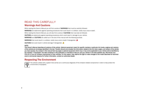 4
4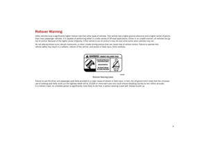 5
5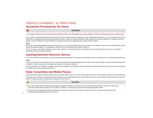 6
6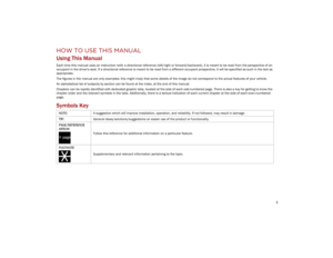 7
7 8
8 9
9 10
10 11
11 12
12 13
13 14
14 15
15 16
16 17
17 18
18 19
19 20
20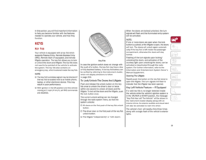 21
21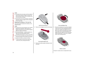 22
22 23
23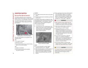 24
24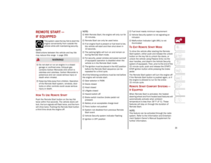 25
25 26
26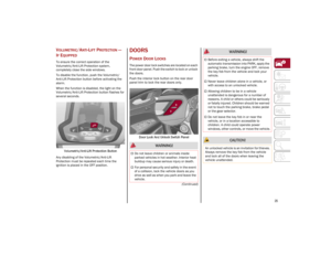 27
27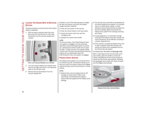 28
28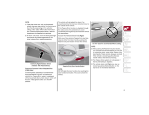 29
29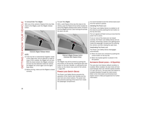 30
30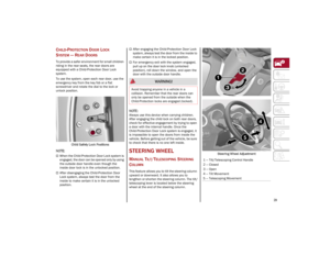 31
31 32
32 33
33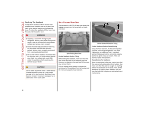 34
34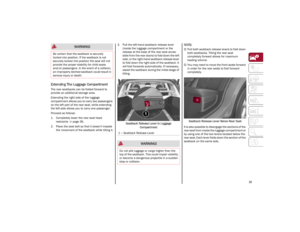 35
35 36
36 37
37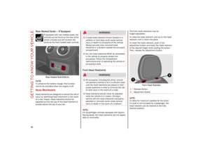 38
38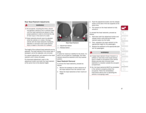 39
39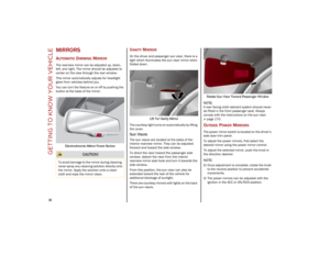 40
40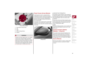 41
41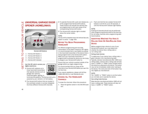 42
42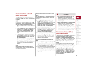 43
43 44
44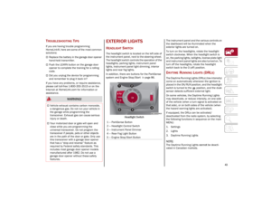 45
45 46
46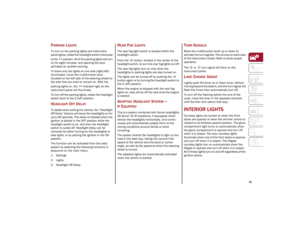 47
47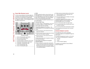 48
48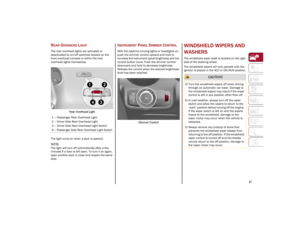 49
49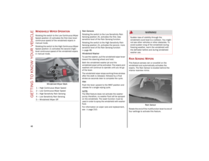 50
50 51
51 52
52 53
53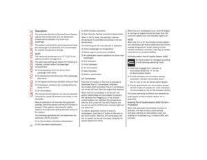 54
54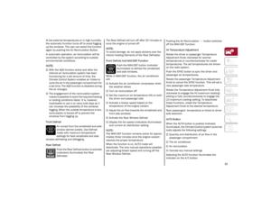 55
55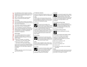 56
56 57
57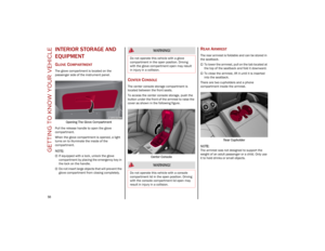 58
58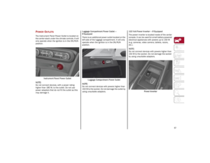 59
59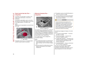 60
60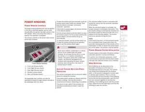 61
61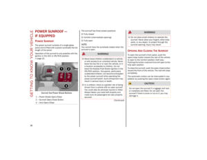 62
62 63
63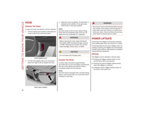 64
64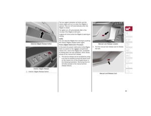 65
65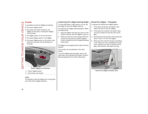 66
66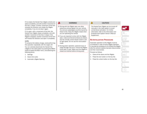 67
67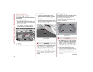 68
68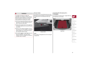 69
69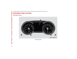 70
70 71
71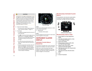 72
72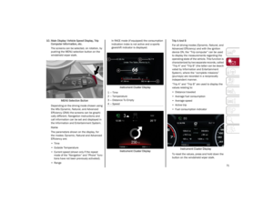 73
73 74
74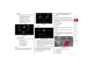 75
75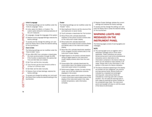 76
76 77
77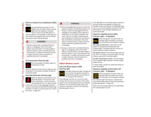 78
78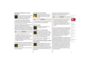 79
79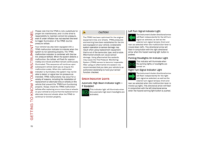 80
80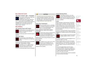 81
81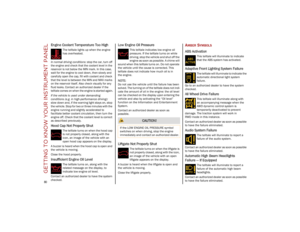 82
82 83
83 84
84 85
85 86
86 87
87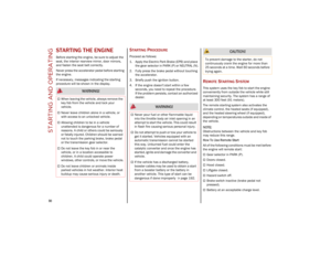 88
88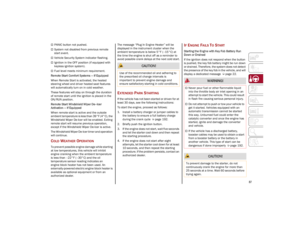 89
89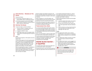 90
90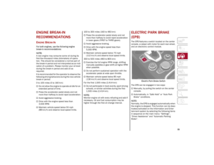 91
91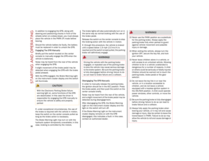 92
92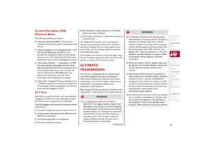 93
93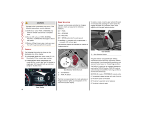 94
94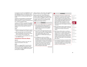 95
95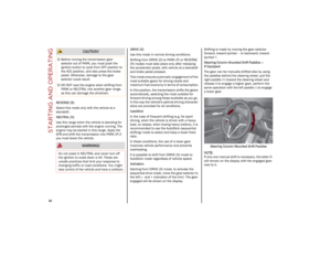 96
96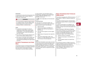 97
97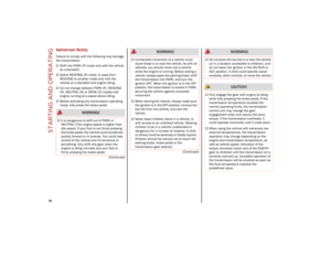 98
98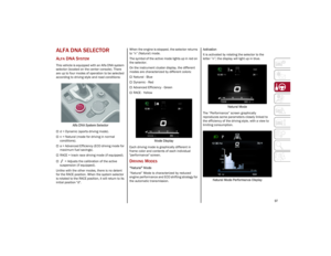 99
99 100
100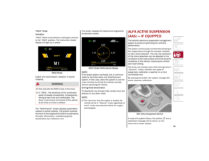 101
101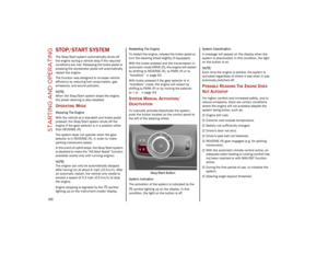 102
102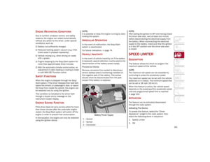 103
103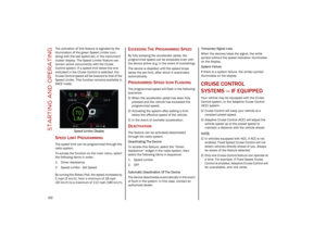 104
104 105
105 106
106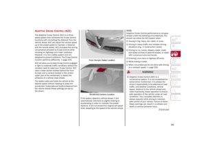 107
107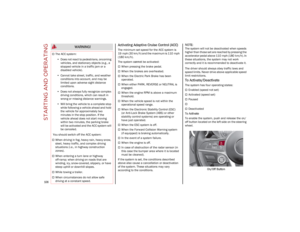 108
108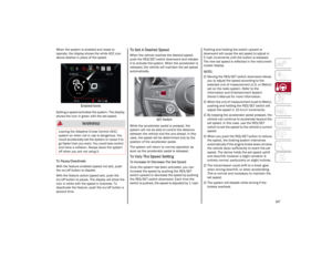 109
109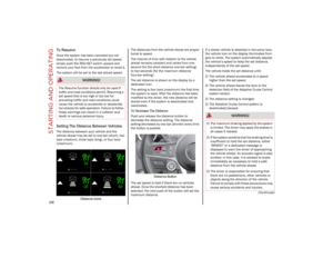 110
110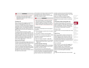 111
111 112
112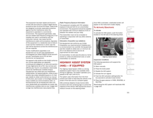 113
113 114
114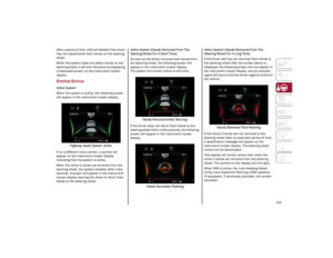 115
115 116
116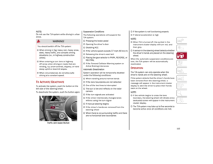 117
117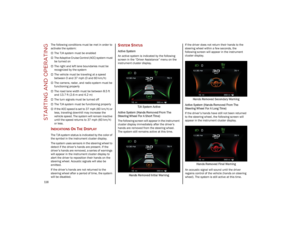 118
118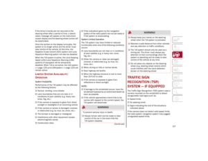 119
119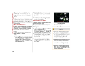 120
120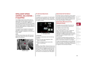 121
121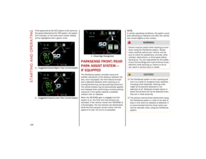 122
122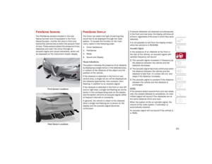 123
123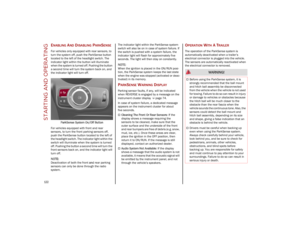 124
124 125
125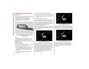 126
126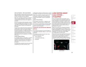 127
127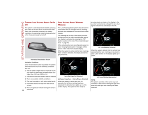 128
128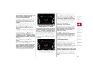 129
129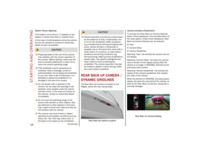 130
130 131
131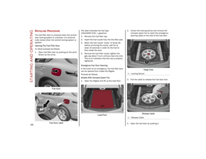 132
132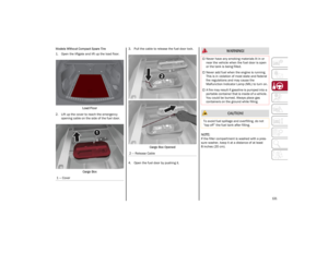 133
133 134
134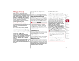 135
135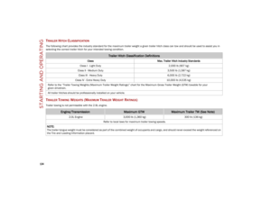 136
136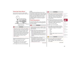 137
137 138
138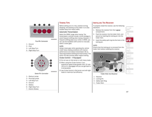 139
139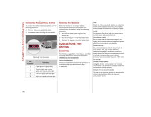 140
140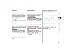 141
141 142
142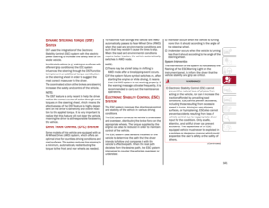 143
143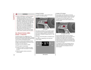 144
144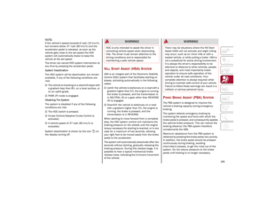 145
145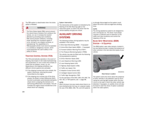 146
146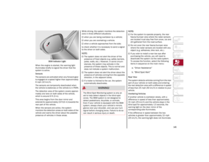 147
147 148
148 149
149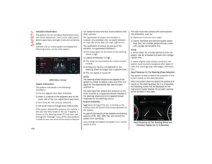 150
150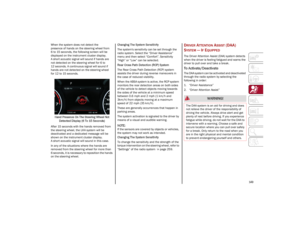 151
151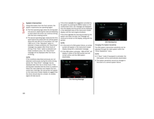 152
152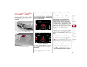 153
153 154
154 155
155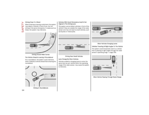 156
156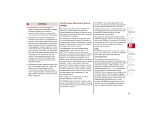 157
157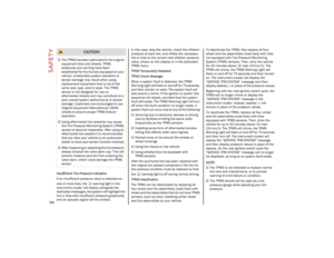 158
158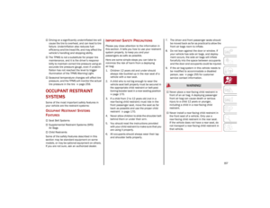 159
159 160
160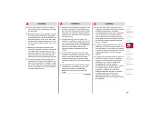 161
161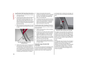 162
162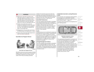 163
163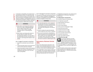 164
164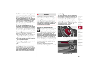 165
165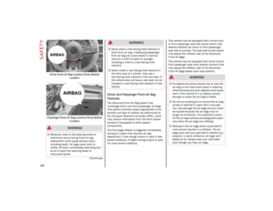 166
166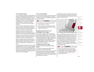 167
167 168
168 169
169 170
170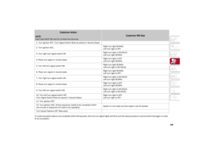 171
171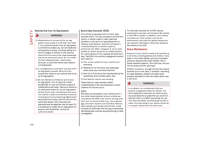 172
172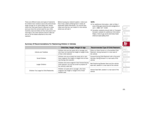 173
173 174
174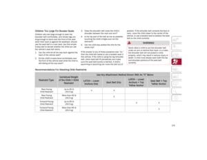 175
175 176
176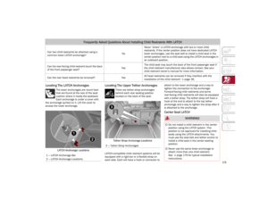 177
177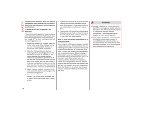 178
178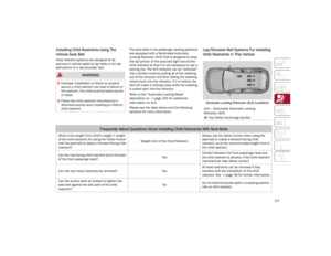 179
179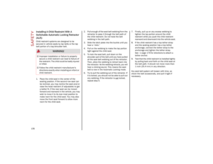 180
180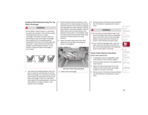 181
181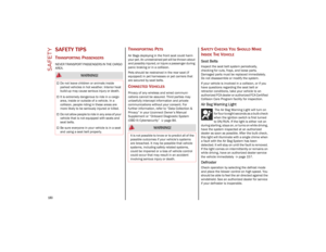 182
182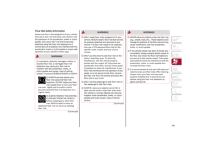 183
183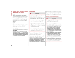 184
184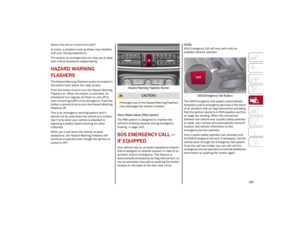 185
185 186
186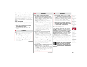 187
187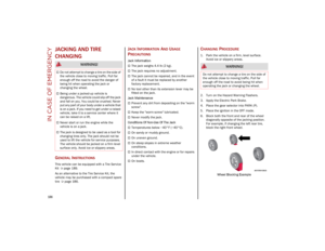 188
188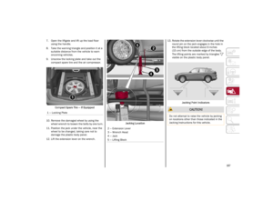 189
189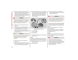 190
190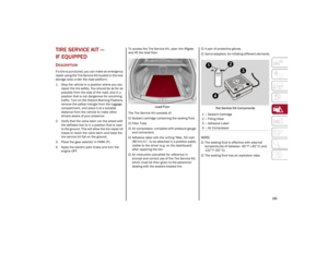 191
191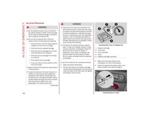 192
192 193
193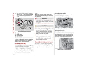 194
194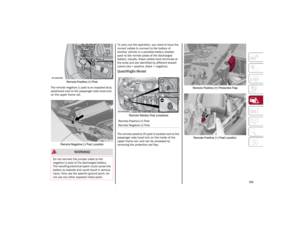 195
195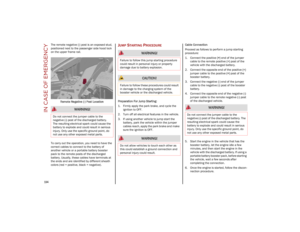 196
196 197
197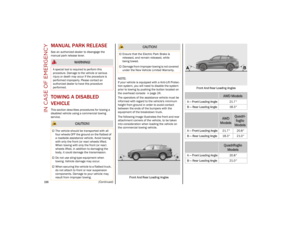 198
198 199
199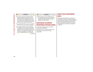 200
200 201
201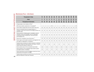 202
202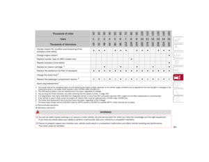 203
203 204
204 205
205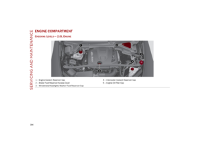 206
206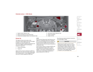 207
207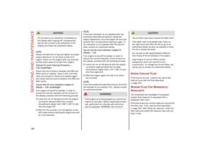 208
208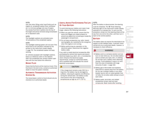 209
209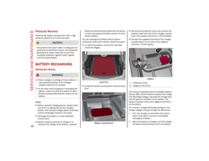 210
210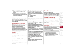 211
211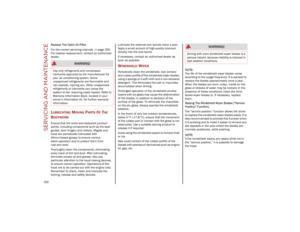 212
212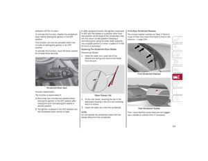 213
213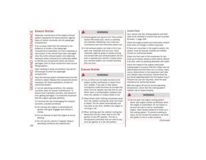 214
214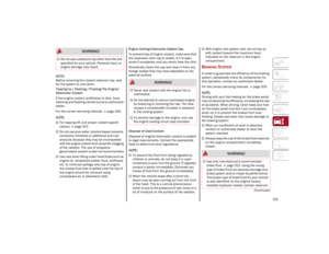 215
215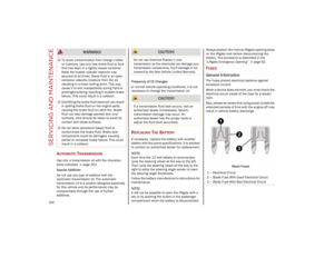 216
216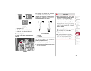 217
217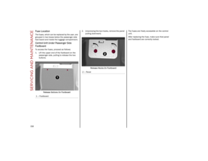 218
218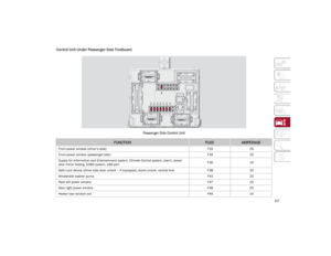 219
219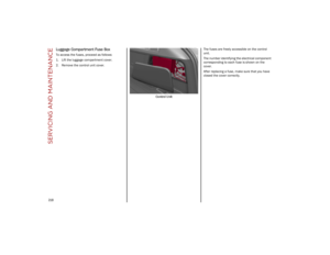 220
220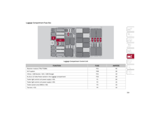 221
221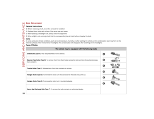 222
222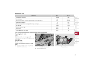 223
223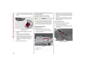 224
224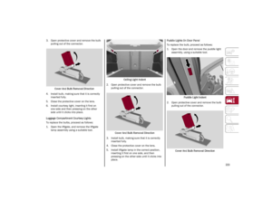 225
225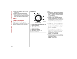 226
226 227
227 228
228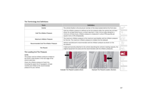 229
229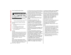 230
230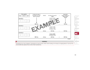 231
231 232
232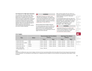 233
233 234
234 235
235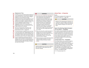 236
236 237
237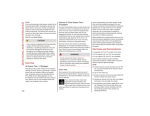 238
238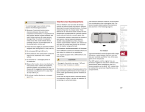 239
239 240
240 241
241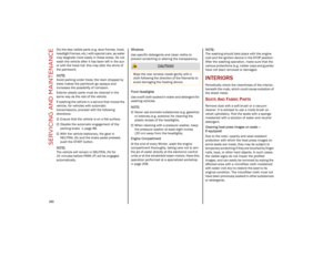 242
242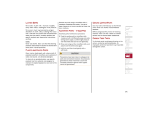 243
243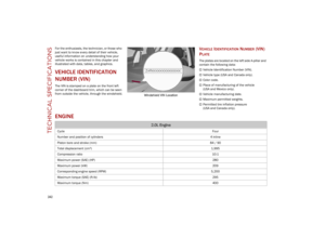 244
244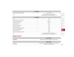 245
245 246
246 247
247 248
248 249
249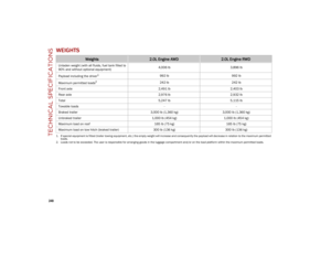 250
250 251
251 252
252 253
253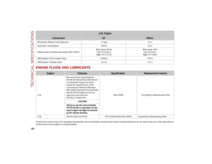 254
254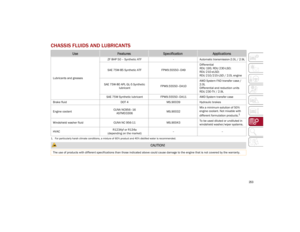 255
255 256
256 257
257 258
258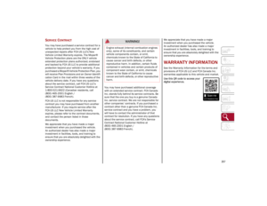 259
259 260
260 261
261 262
262 263
263 264
264 265
265 266
266 267
267