2023 ALFA ROMEO STELVIO fuel pressure
[x] Cancel search: fuel pressurePage 13 of 268

11
LANE DEPARTURE WARNING (LDW)
SYSTEM ................................................. 123
Lane Departure Warning
Operation ..............................................123 Turning Lane Departure Warning On
Or Off .................................................... 124 Lane Departure Warning Message.....124
Changing Lane Departure Warning
Status ................................................... 125
LANE KEEPING ASSIST (LKA) SYSTEM —
IF EQUIPPED .......................................... 125
Turning Lane Keeping
Assist On Or Off ....................................126 Lane Keeping Assist Warning
Message ...............................................126
REAR BACK UP CAMERA / DYNAMIC
GRIDLINES ............................................ 128
REFUELING THE VEHICLE ..................... 129
Refueling Capacity ............................... 129
Refueling Procedure ...........................130
VEHICLE LOADING ................................ 132
Certification Label................................ 132
TRAILER TOWING................................... 133
Common Towing Definitions ...............133
Trailer Hitch Classification .................. 134
Trailer Towing Weights
(Maximum Trailer Weight Ratings) .....134 Trailer And Tongue Weight ................. 135
Towing Requirements..........................135
Towing Tips ......................................... 137
Installing The Receiver ....................... 137
Connecting The Electrical System...... 138
Removing The Receiver ...................... 138
SUGGESTIONS FOR DRIVING................ 138
Saving Fuel .......................................... 138
Driving Style......................................... 139
Conditions Of Use................................ 139
Performance — Quadrifoglio ............... 139
SAFETY
ACTIVE SAFETY SYSTEMS ..................... 140
Anti-Lock Brake System (ABS) ........... 140
Active Torque Vectoring (ATV)
System — If Equipped ......................... 140 Dynamic Steering Torque (DST)
System ................................................. 141 Drive Train Control (DTC) System....... 141
Electronic Stability Control (ESC)
System ................................................. 141 Hill Descent Control (HDC) System —
If Equipped .......................................... 142 Hill Start Assist (HSA) System ............ 143
Panic Brake Assist (PBA) System ....... 143
Traction Control System (TCS)............ 144
AUXILIARY DRIVING SYSTEMS .............. 144
Blind Spot Monitoring (BSM) System —
If Equipped ........................................... 144 Active Blind Spot Assist (ABSA)
System — If Equipped ......................... 146 Driver Attention Assist (DAA) System —
If Equipped ........................................... 149 Forward Collision Warning
Plus (FCW+) System —
If Equipped .......................................... 151 Tire Pressure Monitoring
System (TPMS) .................................... 155
OCCUPANT RESTRAINT SYSTEMS ....... 157
Occupant Restraint Systems
Features .............................................. 157 Important Safety Precautions............. 157
Seat Belt Systems .............................. 158
Supplemental Restraint
Systems (SRS) ..................................... 162 Child Restraints ................................... 170
SAFETY TIPS .......................................... 180
Transporting Passengers .................... 180
Transporting Pets ............................... 180
Connected Vehicles ............................. 180
Safety Checks You Should Make
Inside The Vehicle .............................. 180 Periodic Safety Checks You
Should Make Outside The Vehicle ..... 182 Exhaust Gas ......................................... 182
Carbon Monoxide Warnings................ 182
23_GU_OM_EN_USC_t.book Page 11
Page 16 of 268

SYMBOL GLOSSARY
14
SYMBOL GLOSSARY
Some car components have colored labels with symbols indicating
precautions to be observed when using this component. It is important to
follow all warnings when operating your vehicle. See below for the definition
of each symbol
Ú
page 74.
NOTE:
Warning and Indicator lights are different based upon equipment options
and current vehicle status. Some telltales are optional and may not appear.
Red Warning Lights
Air Bag Warning Light
Ú
page 75
Brake Warning Light
Ú
page 75
Electronic Braking Force Distribution (EBD) Failure
Ú
page 76
Oil Temperature Warning Light
Ú
page 76
Seat Belt Reminder Warning Light
Ú
page 76
Amber Warning Lights
Anti-Lock Brake System (ABS) Warning Light
Ú
page 76
Electronic Stability Control (ESC) Indicator Light
Ú
page 76
Electronic Stability Control (ESC) OFF Indicator Light
Ú
page 76
Engine Check/Malfunction Indicator Light (MIL)
Ú
page 77
Forward Collision Warning (FCW) System
Ú
page 77
Fuel Reserve/Limited Range
Ú
page 77
Rear Fog Lights
Ú
page 77
Tire Pressure Low Warning Light
Ú
page 77
Tire Pressure Monitoring System (TPMS) Warning Light
Ú
page 77
Amber Warning Lights
23_GU_OM_EN_USC_t.book Page 14
Page 18 of 268

SYMBOL GLOSSARY
16
Amber Symbols
ABS Activation
Ú
page 80
Adaptive Front Lighting System Failure
Ú
page 80
Automatic High Beam Headlights Failure
Ú
page 80
Automatic Transmission Fluid Overheating
Ú
page 83
Audio System Failure
Ú
page 80
All Wheel Drive Failure
Ú
page 80
Blind Spot Monitoring System Failure
Ú
page 81
Dusk Sensor Failure
Ú
page 81
Dynamic Drive Control System Failure
Ú
page 81
Driver Attention Assist (DAA) System Failure
Ú
page 81
Electric Park Brake Failure
Ú
page 81
Engine Immobilizer Failure/Break-In Attempt
Ú
page 81
Engine Oil Change Required
Ú
page 81
Engine Oil Pressure Sensor Failure
Ú
page 82
Engine Oil Level Sensor Failure
Ú
page 82
Exterior Lights Failure
Ú
page 81
Forward Collision Warning (FCW) System Failure
Ú
page 83
Fuel Cut-Off Indicator Light
Ú
page 82
Fuel Level Sensor Failure
Ú
page 82
Fuel Cut-Off System Failure
Ú
page 82
Amber Symbols
23_GU_OM_EN_USC_t.book Page 16
Page 75 of 268

73
Dynamic
The display graphically shows the values of:
○ accelerator pedal position (expressed in percentage);
○ brake pedal position (expressed in percentage);
○ engine coolant temperature (H = hot C = cold).
Dynamic
Race (If Equipped)
The display graphically shows the values of:
○ engine torque;
○ turbocharger pressure;
○ engine oil pressure (L = low pressure/
H= high pressure).
NOTE:
The engine torque and turbocharger pressure
values vary according to the engine type. Race
Dynamic
Acceleration Gauge
The displayed parameters are related to vehi -
cle stability, the graphs illustrate the trend of
the longitudinal/lateral accelerations (G-me -
ter information), considering gravity accelera -
tion as a reference unit.
Lateral acceleration peaks are also indicated.
11. Driving Mode Display (Alfa DNA System)
12. Distance Traveled (miles/km) display
13. Fuel Consumption 14. Warning Indications Display (e.g. danger of
ice, open doors, ABS operation, etc.)
15. Range
CUSTOMER PROGRAMMABLE SETTINGS
Multiple settings can be programmed by the user
using the radio. This section describes only the
basic settings:
Units & Language
Clock & Date
Cluster
To access the settings list in the radio, proceed as
follows:
Press the Home button to access the main
menu.
Select Settings from the main menu using the
Rotary Knob or by pressing Settings on the
touchscreen.
Rotary Knob
1 — ON/OFF Control And Volume Knob
2 — OPTION Button
3 — Rotary Pad
4 — Home Button
23_GU_OM_EN_USC_t.book Page 73
Page 79 of 268

77
Engine Check/Malfunction Indicator
Light (MIL)
In normal conditions, when the ignition
is cycled to ON, the indicator light
illuminates, but it should turn off as
soon as the engine is started.
The operation of the indicator light may be
checked by the traffic police using specific
devices. Comply with the laws and regulations of
the country where you are driving.
Under these conditions, the vehicle can continue
traveling at moderate speed but without
demanding excessive effort from the engine or
high speed. Prolonged use of the vehicle with the
indicator light on constantly may cause damage.
Contact an authorized dealer as soon as possible.
Forward Collision Warning (FCW) System
This indicator light informs the driver
that the frontal collision alarm function
is not enabled.
Drive carefully and contact an authorized dealer
as soon as possible.
Fuel Reserve/Limited Range
The indicator light (or the symbol in
the display) illuminates when about
2.4 gallons (9 liters) of fuel is left in
the tank.
Rear Fog Lights
The indicator illuminates when the
rear fog light is activated.
Tire Pressure Low Warning Light
The indicator light will illuminate to
indicate that the tire pressure is lower
than the recommended value and/or
that slow pressure loss is occurring.
In these cases, optimal tire duration and fuel
consumption may not be guaranteed.
In any situation in which the message on the
display is “See Manual”
Ú
page 155.
Tire Pressure Monitoring System (TPMS)
Warning Light
The warning light switches on and a
message is displayed to indicate that
the tire pressure is lower than the
recommended value and/or that slow
pressure loss is occurring. In these cases, optimal
tire duration and fuel consumption may not be
guaranteed. Should one or more tires be in the condition
previously mentioned, the display will show the
indications corresponding to each tire.
Each tire, including the spare (if provided), should
be checked monthly when cold and inflated to the
inflation pressure recommended by the vehicle
manufacturer on the vehicle placard or tire
inflation pressure label. If your vehicle has tires of
a different size than the size indicated on the
vehicle placard or tire inflation pressure label, you
should determine the proper tire inflation
pressure for those tires.
As an added safety feature, your vehicle has been
equipped with a TPMS that illuminates a low tire
pressure telltale when one or more of your tires is
significantly underinflated. Accordingly, when the
low tire pressure telltale illuminates, you should
stop and check your tires as soon as possible,
and inflate them to the proper pressure. Driving
on a significantly underinflated tire causes the
tire to overheat and can lead to tire failure. Under
inflation also reduces fuel efficiency and tire
tread life, and may affect the vehicle’s handling
and stopping ability.
CAUTION!
If, turning the ignition device to ON, the
warning light does not turn on or if it turns
on steadily or flashing while driving (on some
versions together with the message on the
display), immediate service is required.
Prolonged driving with the MIL on could cause
damage to the vehicle.
CAUTION!
If the warning light on the display flashes while
driving, contact an authorized dealer.
CAUTION!
Do not continue driving with one or more flat
tires as handling may be compromised. Stop
the vehicle, avoiding sharp braking and
steering. If a tire puncture occurs, repair
immediately using the dedicated tire repair kit
and contact an authorized dealer as soon as
possible.
23_GU_OM_EN_USC_t.book Page 77
Page 84 of 268

GETTING TO KNOW YOUR INSTRUMENT PANEL
82
Engine Oil Level Sensor Failure
The telltale will illuminate in the event of
engine oil level sensor failure.
Contact an authorized dealer as soon as
possible.
Engine Oil Pressure Sensor Failure
The telltale will illuminate in the event of
engine oil pressure sensor failure.
Contact an authorized dealer as soon as
possible.
Fuel Cut-Off System Failure
The telltale will illuminate in the event of
fuel cut-off system failure.
Contact an authorized dealer as soon as
possible.
Fuel Cut-Off Indicator Light
The telltale will illuminate after an
accident has occurred and the system
has shut the fuel off.
For reactivating the fuel cut-off system
Ú
page 157. If it is not possible to restore the fuel
supply, contact an authorized dealer.
Fuel Level Sensor Failure
The telltale will illuminate in the event of
fuel level sensor failure.
Contact an authorized dealer as soon as
possible.
Generic Indication
Signals information and failures.
The accompanying messages describe the
failure.
Highway Assist System (HAS)/Traffic Jam
Assist (TJA) System Failure
The symbol lights up in case of HAS or
TJA system failure.
Contact an Alfa Romeo Dealership as soon as
possible to have the failure eliminated.
Keyless System Failure
The telltale will illuminate in the event of
keyless system failure.
Contact an authorized dealer as soon as
possible.
Lane Departure Warning (LDW) System
Failure — If Equipped
The telltale will illuminate in the event of
a fault in the Lane Departure Warning
system.
Contact an authorized dealer as soon as
possible.
Loose Fuel Filler Cap
Lights up if the fuel tank cap is open or
not properly closed.
Tighten the cap properly.
Low Coolant Level — If Equipped
This telltale will illuminate to indicate
that the vehicle coolant level is low.
Windshield Washer Liquid Level
The telltale will illuminate to indicate
that the level of the windshield and
headlight washing fluid (if any) is low.
Always use liquid with the features indicated in
the “Fluids And Lubricants”
Ú
page 206.
Park Sensors System Failure
The telltale will illuminate when the
system has failed or is not available.
Contact an authorized dealer to have the system
checked.
Rain Sensor Failure
The telltale will illuminate in the case of
failure of the automatic windshield
wiper.
Contact an authorized dealer as soon as
possible.
Service Adaptive Cruise Control (ACC)
System
This light will illuminate when the ACC is
not operating and needs service.
Contact an authorized dealer to have the system
checked.
23_GU_OM_EN_USC_t.book Page 82
Page 134 of 268

STARTING AND OPERATING
132
VEHICLE LOADING
CERTIFICATION LABEL
As required by National Highway Traffic Safety
Administration regulations, your vehicle has a
certification label affixed to the driver's side door
or pillar.
This label contains the month and year of
manufacture, Gross Vehicle Weight Rating
(GVWR), Gross Axle Weight Rating (GAWR) front
and rear, and Vehicle Identification Number
(VIN). A Month-Day-Hour (MDH) number is
included on this label and indicates the Month,
Day and Hour of manufacture. The bar code that
appears on the bottom of the label is your VIN.
Gross Vehicle Weight Rating (GVWR)
The GVWR is the total permissible weight of your
vehicle including driver, passengers, vehicle,
options and cargo. The label also specifies
maximum capacities of front and rear axle
systems (GAWR). Total load must be limited so
GVWR and front and rear GAWR are not
exceeded.
Payload
The payload of a vehicle is defined as the
allowable load weight a truck can carry, including
the weight of the driver, all passengers, options
and cargo.
Gross Axle Weight Rating (GAWR)
The GAWR is the maximum permissible load on
the front and rear axles. The load must be
distributed in the cargo area so that the GAWR of
each axle is not exceeded.
Each axle GAWR is determined by the
components in the system with the lowest load
carrying capacity (axle, springs, tires or wheels).
Heavier axles or suspension components
sometimes specified by purchasers for increased
durability do not necessarily increase the
vehicle's GVWR.
Tire Size
The tire size on the Vehicle Certification Label
represents the actual tire size on your vehicle.
Replacement tires must be equal to the load
capacity of this tire size.
Rim Size
This is the rim size that is appropriate for the
tire size listed.
Inflation Pressure
This is the cold tire inflation pressure for your
vehicle for all loading conditions up to full GAWR.
Curb Weight
The curb weight of a vehicle is defined as the total
weight of the vehicle with all fluids, including
vehicle fuel, at full capacity conditions, and with
no occupants or cargo loaded into the vehicle.
The front and rear curb weight values are
determined by weighing your vehicle on a
commercial scale before any occupants or
cargo are added.
Loading
The actual total weight and the weight of the front
and rear of your vehicle at the ground can best be
determined by weighing it when it is loaded and
ready for operation.
The entire vehicle should first be weighed on a
commercial scale to ensure that the GVWR has
not been exceeded. The weight on the front and
rear of the vehicle should then be determined
separately to be sure that the load is properly
distributed over the front and rear axle. Weighing
the vehicle may show that the GAWR of either the
front or rear axles has been exceeded but the
total load is within the specified GVWR. If so,
weight must be shifted from front to rear or rear
to front as appropriate until the specified weight
limitations are met. Store the heavier items down
low and be sure that the weight is distributed
equally. Stow all loose items securely before
driving.
Improper weight distributions can have an
adverse effect on the way your vehicle steers and
handles and the way the brakes operate.
WARNING!
Do not load your vehicle any heavier than the
GVWR or the maximum front and rear GAWR. If
you do, parts on your vehicle can break, or it
can change the way your vehicle handles. This
could cause you to lose control. Overloading
can shorten the life of your vehicle.
23_GU_OM_EN_USC_t.book Page 132
Page 140 of 268
STARTING AND OPERATING
138
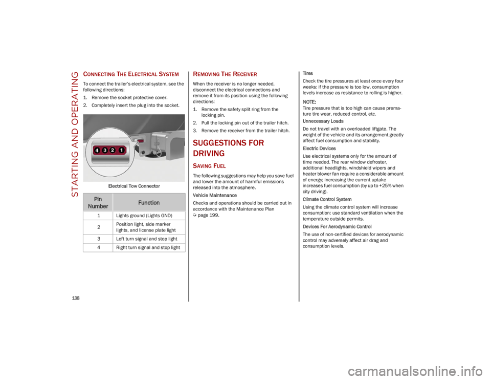
CONNECTING THE ELECTRICAL SYSTEM
To connect the trailer’s electrical system, see the
following directions:
1. Remove the socket protective cover.
2. Completely insert the plug into the socket.Electrical Tow Connector
REMOVING THE RECEIVER
When the receiver is no longer needed,
disconnect the electrical connections and
remove it from its position using the following
directions:
1. Remove the safety split ring from thelocking pin.
2. Pull the locking pin out of the trailer hitch.
3. Remove the receiver from the trailer hitch.
SUGGESTIONS FOR
DRIVING
SAVING FUEL
The following suggestions may help you save fuel
and lower the amount of harmful emissions
released into the atmosphere.
Vehicle Maintenance
Checks and operations should be carried out in
accordance with the Maintenance Plan
Ú
page 199. Tires
Check the tire pressures at least once every four
weeks: if the pressure is too low, consumption
levels increase as resistance to rolling is higher.
NOTE:
Tire pressure that is too high can cause prema
-
ture tire wear, reduced control, etc.
Unnecessary Loads
Do not travel with an overloaded liftgate. The
weight of the vehicle and its arrangement greatly
affect fuel consumption and stability.
Electric Devices
Use electrical systems only for the amount of
time needed. The rear window defroster,
additional headlights, windshield wipers and
heater blower fan require a considerable amount
of energy; increasing the current uptake
increases fuel consumption (by up to +25% when
city driving).
Climate Control System
Using the climate control system will increase
consumption: use standard ventilation when the
temperature outside permits.
Devices For Aerodynamic Control
The use of non-certified devices for aerodynamic
control may adversely affect air drag and
consumption levels.
Pin
NumberFunction
1 Lights ground (Lights GND)
2 Position light, side marker
lights, and license plate light
3 Left turn signal and stop light
4 Right turn signal and stop light
23_GU_OM_EN_USC_t.book Page 138