2022 TOYOTA TUNDRA HYBRID wheel torque
[x] Cancel search: wheel torquePage 187 of 618
1874-1. Before driving
Owners Manual_USA_M0C031_en
4
Driving
A recommended tongue
weight or kingpin weight var-
ies in accordance with the
types of trailers or towing as
described below.
To ensure the recommended
values shown below, the
trailer must be loaded by
referring to the following
instructions.
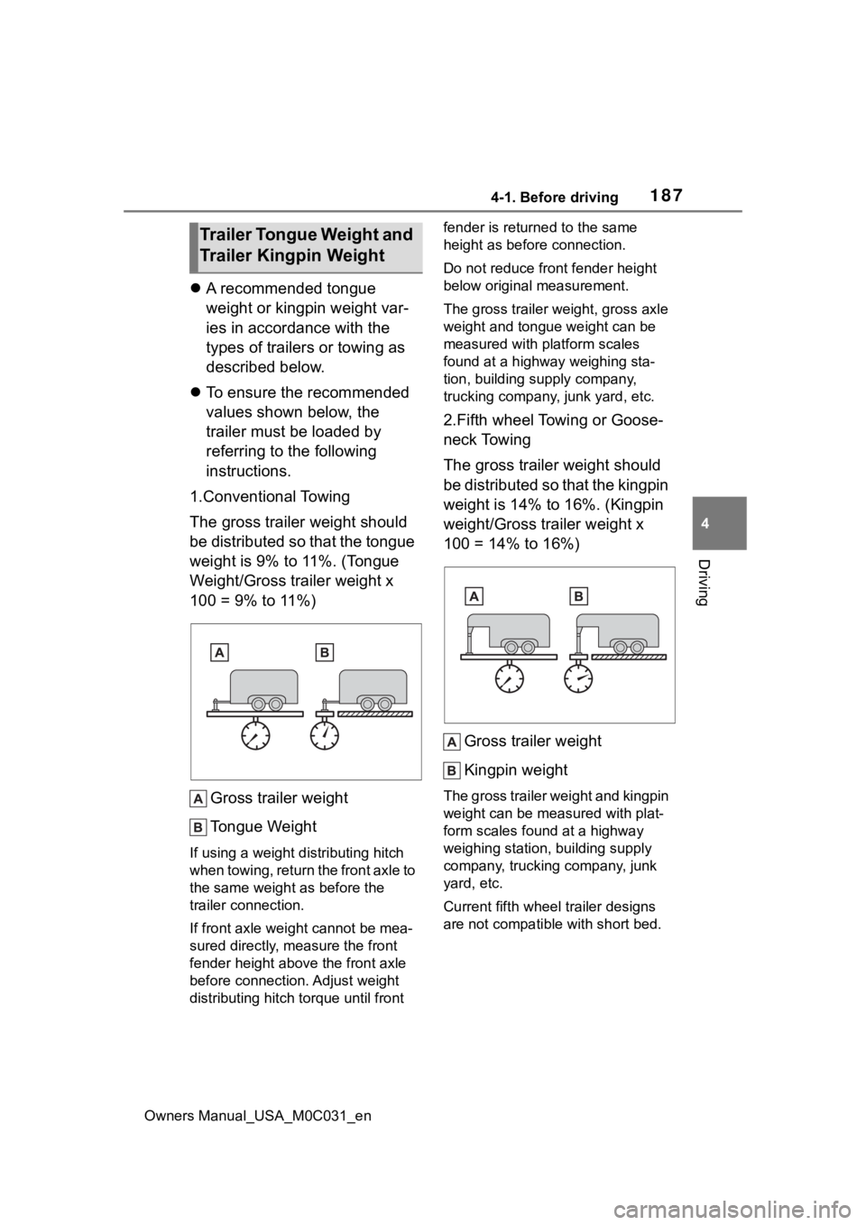
1.Conventional Towing
The gross trailer weight should
be distributed so that the tongue
weight is 9% to 11%. (Tongue
Weight/Gross trailer weight x
100 = 9% to 11%)
Gross trailer weight
Tongue Weight
If using a weight d istributing hitch
when towing, return the front axle to
the same weight as before the
trailer connection.
If front axle weight cannot be mea-
sured directly, measure the front
fender height above the front axle
before connection. Adjust weight
distributing hitch torque until front fender is returned to the same
height as before connection.
Do not reduce front fender height
below original measurement.
The gross trailer weight, gross axle
weight and tongue weight can be
measured with platform scales
found at a highway weighing sta-
tion, building supply company,
trucking company, junk yard, etc.
2.Fifth wheel Towing or Goose-
neck Towing
The gross trailer weight should
be distributed so that the kingpin
weight is 14% to 16%. (Kingpin
weight/Gross trailer weight x
100 = 14% to 16%)
Gross trailer weight
Kingpin weight
The gross trailer weight and kingpin
weight can be measured with plat-
form scales found at a highway
weighing station, building supply
company, trucking company, junk
yard, etc.
Current fifth whee l trailer designs
are not compatible with short bed.
Trailer Tongue Weight and
Trailer Kingpin Weight
Page 233 of 618
2334-5. Using the driving support systems
Owners Manual_USA_M0C031_en
4
Driving
WARNING
●Emergency steering assist may
not operate or may be cancel in
the following cases as the sys-
tem may determine the driver is
taking actions.
• If the accelerato r pedal is being
depressed strongly, the steering
wheel is being operated sharply,
the brake pedal is being
depressed or the turn signal
lever is being ope rated. In this
case, the system may deter-
mine that the driver is taking
evasive action and the emer-
gency steering assist may not
operate.
• The emergency steering assist will be disabled automatically
when the system judges that a
trailer is connected.
• In some situations, while the emergency steering assist is
operating, operation of the func-
tion may be canceled if the
accelerator peda l is depressed
strongly, the st eering wheel is
operated sharply or the brake
pedal is being depressed and
the system determines that the
driver is taking evasive action.
• When the emergency steering assist is operating, if the steer-
ing wheel is held firmly or is
operated in the opposite direc-
tion to that which the system is
generating torque, the function
may be canceled.
■When to disable the pre-colli-
sion system
In the following situations, disable
the system, as it may not operate
properly, possibly leading to an
accident resulting in death or seri-
ous injury:
●When the vehicle is being towed
●When your vehicles is towing a
trailer or another vehicle, except
when the followin g conditions
are all met
• When the other vehicle is a trailer properly attached and
connected to Toyota’s official
TBC ECU. ( P.181)
• When the vehicle is not being driven on a slippery surface
such as an icy road or a very
wet road.
●When transporting the vehicle
via truck, boat, train or similar
means of transportation
●When the vehicle is raised on a
lift with the hybrid system on
and the tires are allowed to
rotate freely
●When inspecting the vehicle
using a drum tester such as a
chassis dynamometer or speed-
ometer tester, or when using an
on vehicle wheel balancer
●When a strong impact is applied
to the front bumper or front
grille, due to an accident or
other reasons
●If the vehicle cannot be driven in
a stable manner, such as when
the vehicle has been in an acci-
dent or is malfunctioning
●When the vehicle is driven in a
sporty manner or off-road
●When the tires are not properly
inflated
●When the tires are very worn
●When tires of a size other than
specified are installed
●When tire chains are installed
●When a compact spare tire or
an emergency tire puncture
repair kit is used
Page 374 of 618

3744-5. Using the driving support systems
Owners Manual_USA_M0C031_en
system detects a panic stop sit-
uation
■Enhanced VSC (Enhanced
Vehicle Stability Control)
Provides cooperative control of
the ABS, TRAC, VSC and EPS.
Helps to maintai n directional
stability when swerving on slip-
pery road surfaces by con-
trolling steering performance.
■Trailer Sway Control
Helps the driver to control trailer
sway by selectively applying
brake pressure for individual
wheels and reducing driving
torque when trailer sway is
detected.
■TRAC (Traction Control)
Helps to maintain drive power
and prevent the drive wheels
from spinning when starting the
vehicle or accelerating on slip-
pery roads
■Hill-start assist control
Helps to reduce the backward
movement of the vehicle when
starting on an uphill
■AVS (Adaptive Variable
Suspension System) (if
equipped)
The damping force of the shock
absorbers are independently
controlled for the 4 wheels
according to factors including
the road surface conditions and
driving operation, contributing
toward enhancing smooth driv- ing comfort and superior stabil-
ity, and helping to maintain
vehicle posture.
In addition, the damping force
can be changed by selecting the
drive mode with the driving
mode select (
P.358), and driv-
ing comfort can be ensured
during off-road driving by setting
the front-wheel drive control
switch to “4L”.( P.361)
■EPS (Electric Power Steer-
ing)
Employs an electric motor to
reduce the amount of effort
needed to turn the steering
wheel
■The Secondary Collision
Brake
When the SRS airbag sensor
detects a collision and the sys-
tem operates, the brakes and
brake lights are automatically
controlled to reduce the vehicle
speed and help reduce the pos-
sibility of further damage due to
a secondary collision.
■When the
TRAC/VSC/ABS/Trailer Sway
Control systems are operating
The slip indicator light will flash
while the TRAC/VSC/ABS/Trailer
Sway Control systems are operat-
ing.
Page 514 of 618
5167-2. Steps to take in an emergency
Owners Manual_USA_M0C031_en
When replacing tires on a vehi-
cle with wheel lock nuts, use the
following procedures to remove
and install the wheel lock nuts.
The wheel lock key is stored in
the glove box. Always return the
wheel lock key to its original
position after use, so that it does not get lost. (
P.515)
■Removal
For ease of removal, the wheel
lock nut should always be the
first one loosened.
1 Place the wheel lock key on
top of the wheel lock nut,
turning until the wheel lock
key and wheel lock nut pat-
terns engage.
2 Place the wheel nut wrench
on the wheel lock key, and
while applying pressure on
the wheel lock key, loosen
the wheel lock nut.
■Installation
For ease of installation, the
wheel lock nut should always be
the last one tightened.
1 By hand, install a wheel lock
nut on each wheel.
2 Place the wheel lock key on
top of the wheel lock nut,
turning until the wheel lock
key and wheel lock nut pat-
terns engage.
3 Place the wheel nut wrench
on the wheel lock key, and
while applying pressure on
the wheel lock key, tighten
the wheel lock nut to the rec-
ommended torque.
WARNING
●Put the jack prope rly in its jack
point.
●Do not put any part of your body
under the vehicle while it is sup-
ported by the jack.
●Do not start the hybrid system
or drive the vehicle while the
vehicle is suppor ted by the jack.
●Do not raise the vehicle while
someone is inside.
●When raising the vehicle, do not
put an object on or under the
jack.
●Do not raise the vehicle to a
height greater than that required
to replace the tire.
●Use a jack stand if it is neces-
sary to get under the vehicle.
●When lowering the vehicle,
make sure that there is no-one
near the vehicle. If there are
people nearby, warn them
vocally before lowering.
■Using the jack handle
Insert the square head securely
until you hear a click to prevent
the extension parts from coming
apart unexpectedly.
Wheel lock nut (if
equipped)
Page 519 of 618
5217-2. Steps to take in an emergency
Owners Manual_USA_M0C031_en
7
When trouble arises
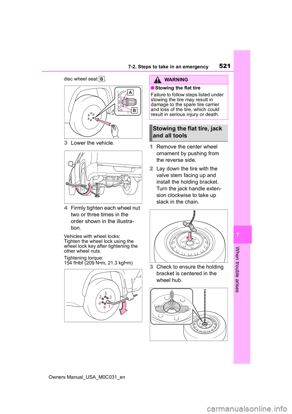
disc wheel seat .
3 Lower the vehicle.
4 Firmly tighten each wheel nut
two or three times in the
order shown in the illustra-
tion.
Vehicles with wheel locks:
Tighten the wheel lock using the
wheel lock key after tightening the
other wheel nuts.
Tightening torque:
154 ft•lbf (209 N•m, 21.3 kgf•m)
1Remove the center wheel
ornament by pushing from
the reverse side.
2 Lay down the tire with the
valve stem facing up and
install the holding bracket.
Turn the jack handle exten-
sion clockwise to take up
slack in the chain.
3 Check to ensure the holding
bracket is centered in the
wheel hub.
WARNING
■Stowing the flat tire
Failure to follow steps listed under
stowing the tire may result in
damage to the spare tire carrier
and loss of the tire, which could
result in serious injury or death.
Stowing the flat tire, jack
and all tools
Page 520 of 618
5227-2. Steps to take in an emergency
Owners Manual_USA_M0C031_en
4While raising, secure the tire,
taking care that the tire goes
straight up without catching
on any surrounding part, to
prevent it from flying forward
during a collision or sudden
braking.
Tightening torque:
34.7 ft•lbf (46.6 N•m, 4.8 kgf•m)
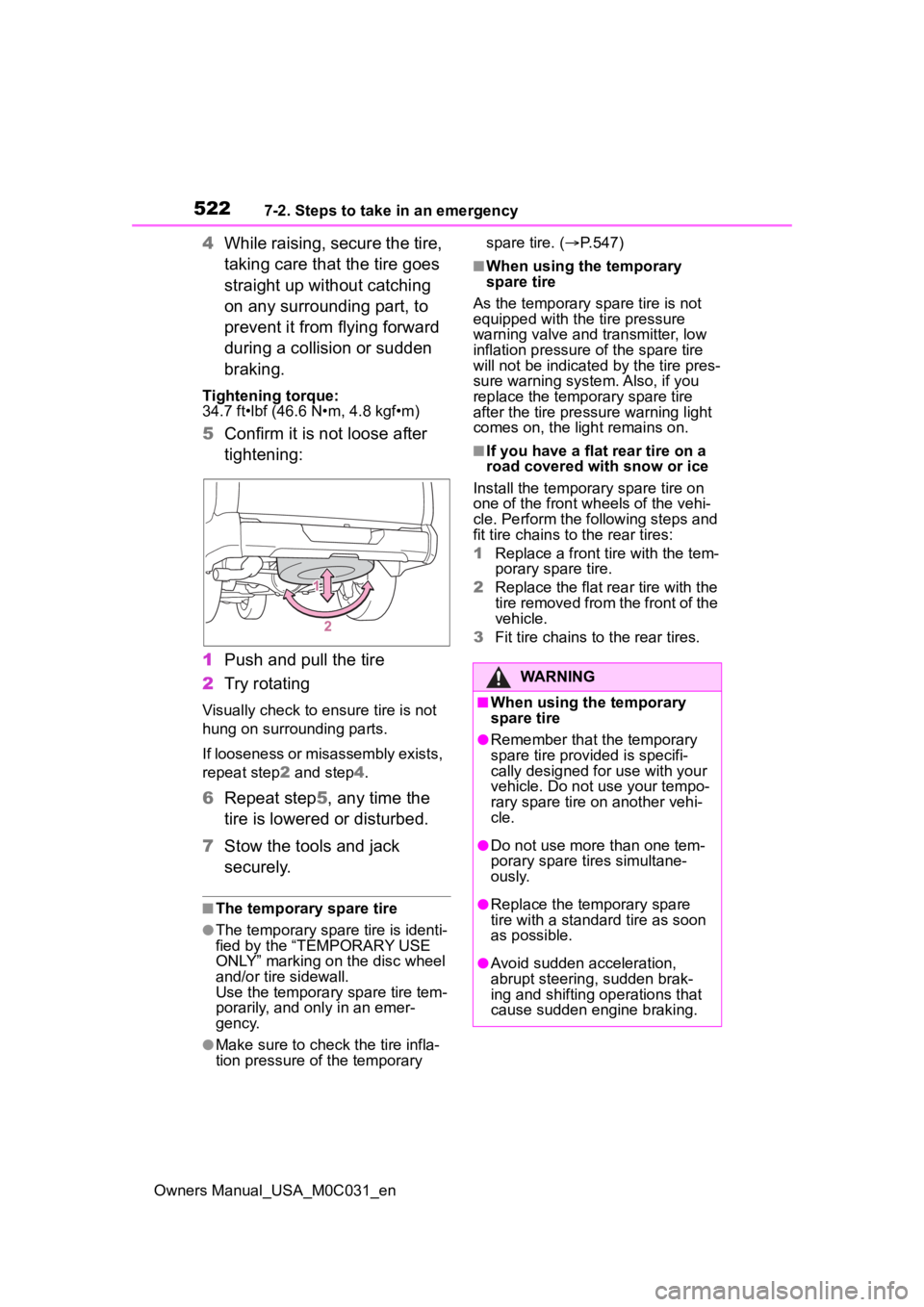
5Confirm it is not loose after
tightening:
1 Push and pull the tire
2 Try rotating
Visually check to ensure tire is not
hung on surrounding parts.
If looseness or misassembly exists,
repeat step 2 and step 4.
6 Repeat step5, any time the
tire is lowered or disturbed.
7 Stow the tools and jack
securely.
■The temporary spare tire
●The temporary spare tire is identi-
fied by the “TEMPORARY USE
ONLY” marking on the disc wheel
and/or tire sidewall.
Use the temporary spare tire tem-
porarily, and only in an emer-
gency.
●Make sure to check the tire infla-
tion pressure of the temporary spare tire. (
P.547)
■When using the temporary
spare tire
As the temporary spare tire is not
equipped with the tire pressure
warning valve and transmitter, low
inflation pressure of the spare tire
will not be indicated by the tire pres-
sure warning system. Also, if you
replace the temporary spare tire
after the tire pressure warning light
comes on, the light remains on.
■If you have a flat rear tire on a
road covered with snow or ice
Install the temporary spare tire on
one of the front w heels of the vehi-
cle. Perform the following steps and
fit tire chains to the rear tires:
1 Replace a front tire with the tem-
porary spare tire.
2 Replace the flat rear tire with the
tire removed from the front of the
vehicle.
3 Fit tire chains to the rear tires.
WARNING
■When using the temporary
spare tire
●Remember that t he temporary
spare tire provided is specifi-
cally designed for use with your
vehicle. Do not use your tempo-
rary spare tire on another vehi-
cle.
●Do not use more than one tem-
porary spare tires simultane-
ously.
●Replace the temporary spare
tire with a standa rd tire as soon
as possible.
●Avoid sudden acceleration,
abrupt steering, sudden brak-
ing and shifting operations that
cause sudden engine braking.
Page 545 of 618
5478-1. Specifications
Owners Manual_USA_M0C031_en
8
Vehicle specifications
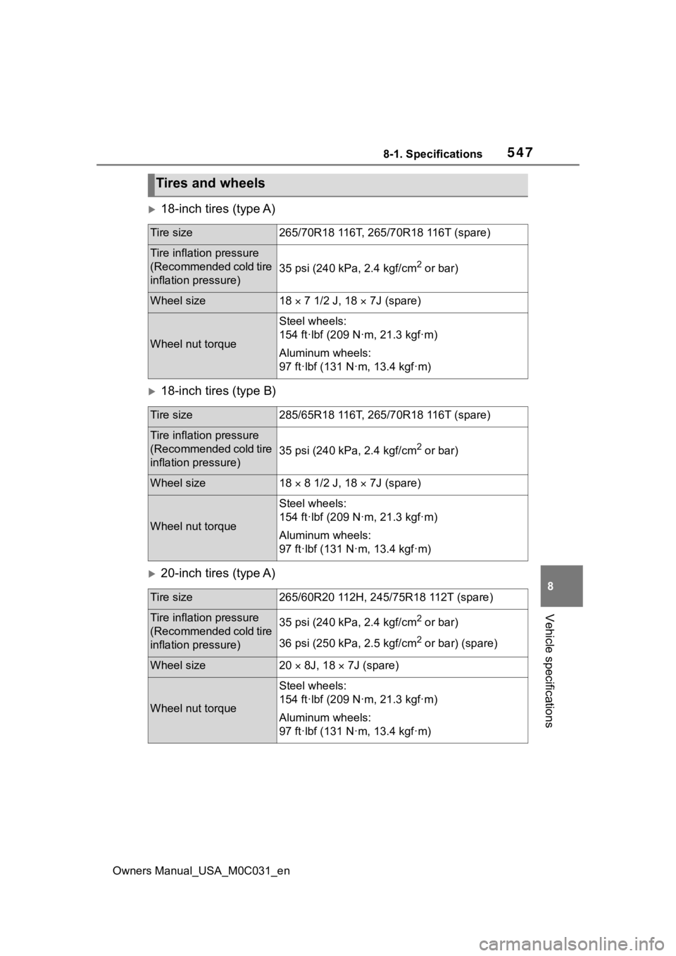
18-inch tires (type A)
18-inch tires (type B)
20-inch tires (type A)
Tires and wheels
Tire size265/70R18 116T, 265/70R18 116T (spare)
Tire inflation pressure
(Recommended cold tire
inflation pressure)
35 psi (240 kPa, 2.4 kgf/cm2 or bar)
Wheel size18 7 1/2 J, 18 7J (spare)
Wheel nut torque
Steel wheels:
154 ft·lbf (209 N·m, 21.3 kgf·m)
Aluminum wheels:
97 ft·lbf (131 N·m, 13.4 kgf·m)
Tire size285/65R18 116T, 265/70R18 116T (spare)
Tire inflation pressure
(Recommended cold tire
inflation pressure)
35 psi (240 kPa, 2.4 kgf/cm2 or bar)
Wheel size18 8 1/2 J, 18 7J (spare)
Wheel nut torque
Steel wheels:
154 ft·lbf (209 N·m, 21.3 kgf·m)
Aluminum wheels:
97 ft·lbf (131 N·m, 13.4 kgf·m)
Tire size265/60R20 112H, 245/75R18 112T (spare)
Tire inflation pressure
(Recommended cold tire
inflation pressure)35 psi (240 kPa, 2.4 kgf/cm2 or bar)
36 psi (250 kPa, 2.5 kgf/cm
2 or bar) (spare)
Wheel size20 8J, 18 7J (spare)
Wheel nut torque
Steel wheels:
154 ft·lbf (209 N·m, 21.3 kgf·m)
Aluminum wheels:
97 ft·lbf (131 N·m, 13.4 kgf·m)
Page 546 of 618
5488-1. Specifications
Owners Manual_USA_M0C031_en
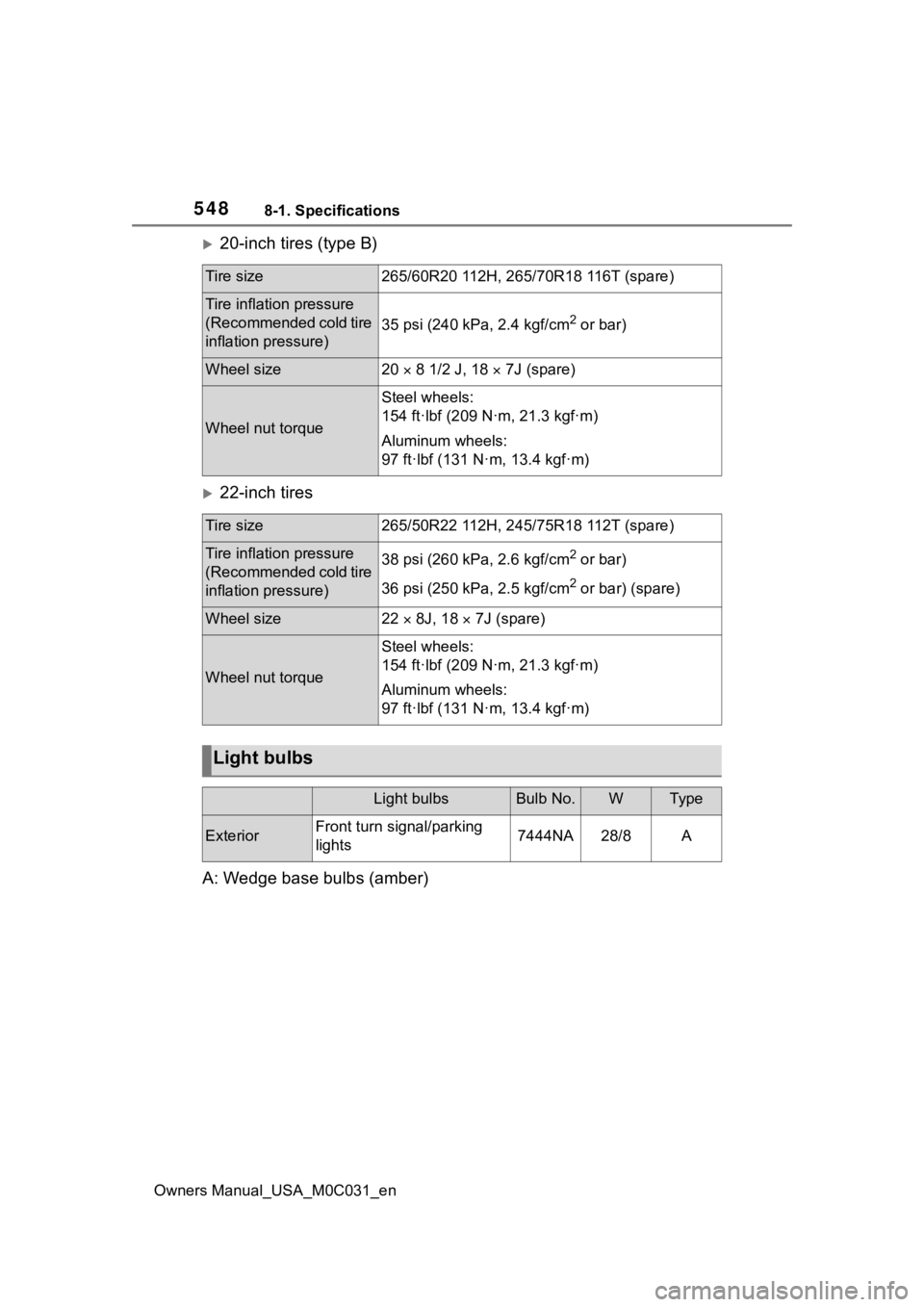
20-inch tires (type B)
22-inch tires
A: Wedge base bulbs (amber)
Tire size265/60R20 112H, 265/70R18 116T (spare)
Tire inflation pressure
(Recommended cold tire
inflation pressure)
35 psi (240 kPa, 2.4 kgf/cm2 or bar)
Wheel size20 8 1/2 J, 18 7J (spare)
Wheel nut torque
Steel wheels:
154 ft·lbf (209 N·m, 21.3 kgf·m)
Aluminum wheels:
97 ft·lbf (131 N·m, 13.4 kgf·m)
Tire size265/50R22 112H, 245/75R18 112T (spare)
Tire inflation pressure
(Recommended cold tire
inflation pressure)38 psi (260 kPa, 2.6 kgf/cm2 or bar)
36 psi (250 kPa, 2.5 kgf/cm
2 or bar) (spare)
Wheel size22 8J, 18 7J (spare)
Wheel nut torque
Steel wheels:
154 ft·lbf (209 N·m, 21.3 kgf·m)
Aluminum wheels:
97 ft·lbf (131 N·m, 13.4 kgf·m)
Light bulbs
Light bulbsBulb No.WTy pe
ExteriorFront turn signal/parking
lights7444NA28/8A