2022 TOYOTA SUPRA warning light
[x] Cancel search: warning lightPage 225 of 498

223
3
3-1. CONTROLS
CONTROLS
If the turn indicator is switched on
while a vehicle is in the critical area,
the steering wheel vibrates briefly
and the light in the exterior mirror
flashes brightly.
The warning is terminated when the
turn signal is cancelled or the other
vehicle has left the critical area.
A flashing light when the vehicle is
unlocked indicates that the system
is performing a self-test.
At speeds over approx. 250 km/h,
155 mph, the system is temporarily
disabled.
At speeds below approx. 250 km/h,
155 mph, the system once again
responds according to the setting.
For further information:
• Radar sensors, see page 50.
The system may have limited func-
tionality in the following situations,
for example:
If the speed of the approaching
vehicle is significantly higher
than the driver's own speed.
In thick fog, wet conditions or
snow.
On sharp bends or narrow roads.
If the bumper is dirty, iced up or
covered, for example by stickers.
After work performed incorrectly
on the vehicle paintwork.
When a projecting load is being
transported.
Attaching any objects – stickers or
film, for example – in the beam
area of the radar sensors will also
restrict the function of the radar
sensors and may even cause them
to fail.
A vehicle message is displayed in
the event of limited functionality.
Depending on the selected setting
for warnings, for example the warn-
ing time, it is po ssible for more
warnings to be displayed. As a
result, there may be an increased
Acute warning
Flashing of light
System limits
Safety note
WA R N I N G
The system may not re spond at all, or
may respond too late, incorrectly or
without justification due to limits of the system. There is a danger of acci-
dents or damage to property.
Observe the information on the sys- tem limits and intervene actively if
necessary.
Upper speed limit
System limits of the sensors
Functional limitations
Warning displays
Page 226 of 498

2243-1. CONTROLS
number of premature warnings
about critical situations.
Depending on the equipment and
the nationalmarket version, the
Rear Collision Prevention can
respond to vehicles approaching
from behind.
Radar sensors monitor the area
behind the vehicle.
If a vehicle is approaching from
behind at a relevant speed, the sys-
tem can respond as follows:
The hazard warning lights are
switched on if appropriate.
PreCrash functions are trig-
gered if appropriate.
The system is controlled using the
following sensors:
• Side radar sensors, rear.
For further information:
Sensors of the vehicle, see page
50.
The system is automatically acti-
vated at the start of each journey.
The system is deactivated in the
following situations:
Prevention of rear collision
Principle
General
Safety notes
WA R N I N G
The system does not relieve you of
your personal responsibility to assess the visibility conditions and traffic situ-
ation correctly. There is a danger of
accidents. Adapt your driving style to the traffic conditions. Observe the
traffic situation and intervene actively
if the situation warrants it.
WA R N I N G
Displays and warnings do not relieve
you of your personal responsibility.
System limitations can mean that warnings or system responses are
not issued or are issued too late,
incorrectly or without justification. There is a danger of accidents. Adapt
your driving style to the traffic condi-
tions. Observe the traffic situation and intervene actively if the situation war-
rants it.
Overview
Sensors
Switching on/off
Page 227 of 498

225
3
3-1. CONTROLS
CONTROLS
When reversing.
For further information:
• Radar sensors, see page 50.
The system may ha ve restricted
functionality in the following situa-
tions:
The speed of the approaching
vehicle is much faster than your
own speed.
The approaching vehicle is
approaching slowly.
The brake lights flash to warn road
users behind the vehicle that emer-
gency braking is being performed.
Normal braking: brake lights illu-
minate.
Heavy braking: brake lights flash.
Shortly before the vehicle comes to
a standstill, th e hazard warning
lights are activated.
To switch off the hazard warning
lights:
Accelerate.
Press the hazard warning lights
button.
The system can automatically bring
the vehicle to a standstill in certain
accident situations without the
involvement of the driver. The risk
of a further collision and its conse-
quences can thereby be reduced.
After the vehicle has come to a halt,
the brake is released automatically.
In certain situations, it may be nec-
essary to bring the vehicle to a
standstill more quickly than is pos-
sible with automatic braking.
To do so, brake quickly and firmly.
For a brief period, the braking pres-
sure will be higher than that
System limits
System limits of the sensors
Functional limitations
Emergency brake lights
Principle
General
Autonomous Emergency
Braking
Principle
At a standstill
Harder vehicle braking
Page 233 of 498

231
3
3-1. CONTROLS
CONTROLS
what limited driving stability.
Activating Traction mode provides
maximum traction. Driving stability
during acceleration and cornering is
limited.
Activating Traction mode briefly
may be useful in the following situa-
tions:
When driving in slush or on
uncleared, snow-covered roads.
When starting in deep snow or
on a loose surface.
When driving with snow chains.
When Traction mode is activated,
TRACTION is displayed in the
instrument cluster.
In certain situations, VSC is acti-
vated automatically:
If Dynamic radar cruise control
with full-speed range is acti-
vated.
General
Overview
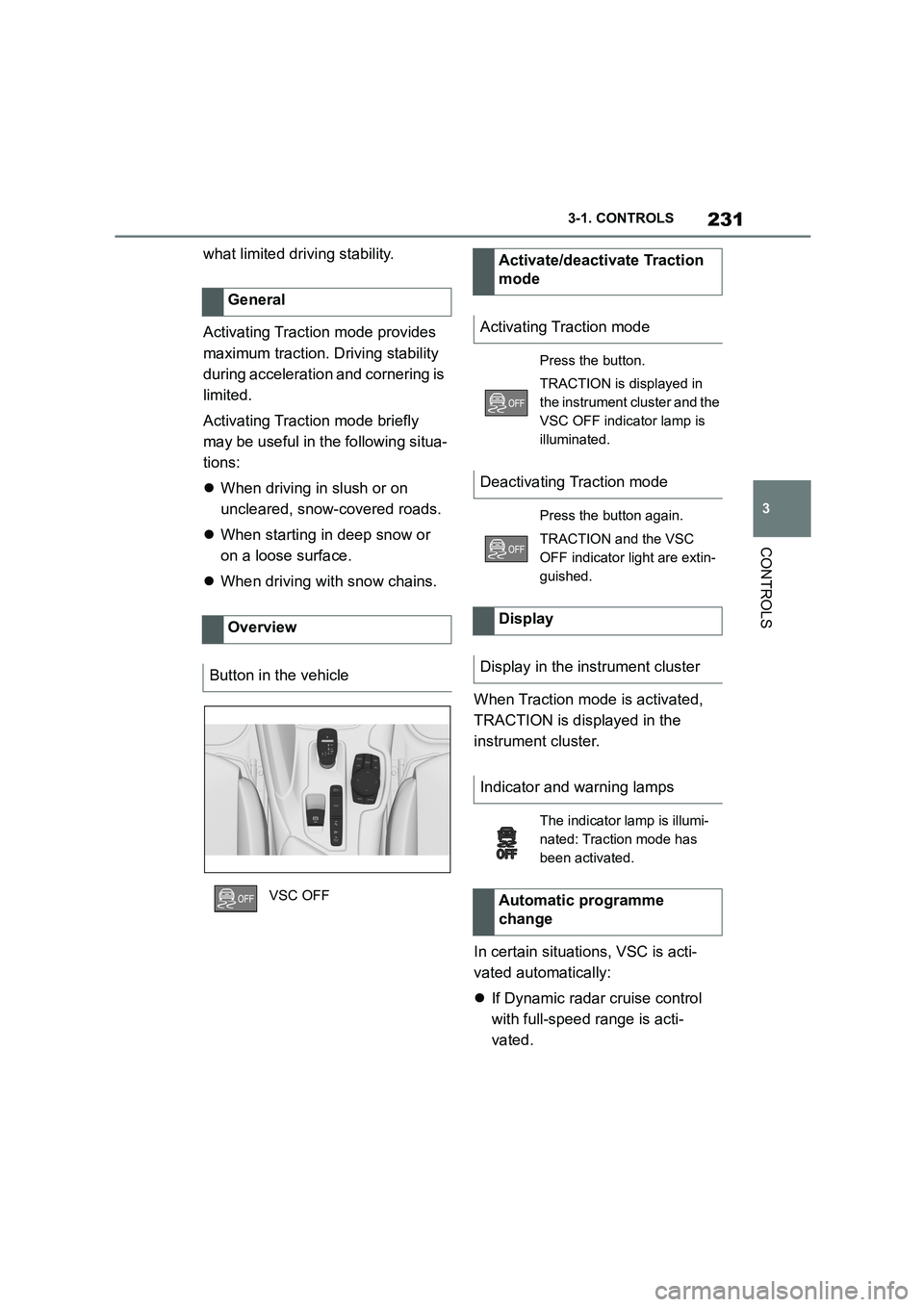
Button in the vehicle
VSC OFF
Activate/deactivate Traction
mode
Activating Traction mode
Press the button.
TRACTION is displayed in
the instrument cluster and the
VSC OFF indicator lamp is
illuminated.
Deactivating Traction mode
Press the button again.
TRACTION and the VSC
OFF indicator light are extin-
guished.
Display
Display in the instrument cluster
Indicator and warning lamps
The indicator lamp is illumi-
nated: Traction mode has
been activated.
Automatic programme
change
Page 253 of 498

251
3
3-1. CONTROLS
CONTROLS
The approach of the vehicle to an
object is shown on the Control Dis-
play. Objects that are further away
are already displayed before an
acoustic signal is given.
The display appears as soon as
Parking Sensor is activated.
The recording range of the sensors
is shown in green, yellow and red if
obstacles are detected within the
range.
Driving path lines are displayed for
better estimation of the space
required.
If the rear-view camera image is
shown, it is possible to change over
to Parking Sensor or, if required, to
another view with obstacle mark-
ings:
1 If necessary, push the Controller
to the left.
2 For example "Parking sensors"
RCTA (Rear cross traffic alert) func-
tion, see page 256: depending on
the equipment, the Parking Sensor
display also warn s about vehicles
approaching from the sides at the
front and rear.
The emergency brake function of
Parking Sensor in itiates emergency
braking if there is an imminent risk
of a collision.
Due to the system limits, a collision
cannot be prevented under all cir-
cumstances.
The function is available at speeds
below walking speed when driving
or rolling in reverse.
Pressing the accelerator pedal
interrupts the braking intervention.
After emergency braking to a stop,
it is possible to continue a slow
approach to the obstacle. To
approach, lightly depress the accel-
erator.
If the accelerator is depressed
more firmly, the vehicle pulls away
as normal. Manual braking is possi-
ble at any time.
The system uses the ultrasonic
sensors of Parking Sensor and
Park Assistant.
Visual warning
Depending on the equipment
version: emergency braking
function, Parking Sensors
with emergency braking
function
Principle
General
Page 260 of 498

2583-1. CONTROLS
2"Vehicle settings"
3 "Parking"
4 "Cross-traffic alert"
5 "Cross-traffic alert"
If the system was activated on the
Control Display, it is switched on
automatically as soon as Parking
Sensors or Panorama View is
active and a gear is engaged.
The system is switched on at the
rear when reverse gear is engaged.
The system switches off automati-
cally in the following situations:
If walking speed is exceeded.
When a certain distance is
exceeded.
During active parking with the
Park Assistant.
The Control Display shows the cor-
responding display, an acoustic sig-
nal may sound and the light in the
exterior mirror flashes.
The light in the exterior mirror
flashes if other vehicles are
detected by the rear sensors when
the vehicle is moving backwards.
In the Parking Sensors view, the
relevant boundary area flashes red
if the sensors detect vehicles.
In addition to the visual display, a
warning signal sounds when your
own vehicle is moving in the corre-
sponding direction.
Switching on automatically
Switching off automatically
Warning
General
Light in the exterior mirror
Display in the Parking Sensors
view
Acoustic warning
Page 301 of 498

299
5
5-1. MOBILITY
MOBILITY
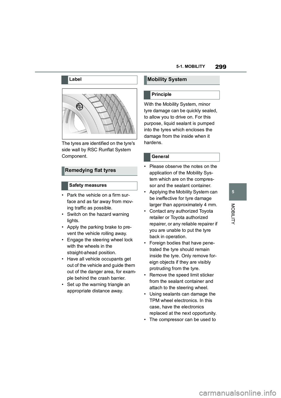
The tyres are identified on the tyre's
side wall by RSC Runflat System
Component.
• Park the vehicle on a firm sur-
face and as far away from mov-
ing traffic as possible.
• Switch on the hazard warning
lights.
• Apply the parking brake to pre-
vent the vehicle rolling away.
• Engage the steering wheel lock
with the wheels in the
straight-ahead position.
• Have all vehicle occupants get
out of the vehicle and guide them
out of the danger area, for exam-
ple behind the crash barrier.
• Set up the warning triangle an
appropriate distance away.
With the Mobility System, minor
tyre damage can be quickly sealed,
to allow you to drive on. For this
purpose, liquid sealant is pumped
into the tyres which encloses the
damage from the inside when it
hardens.
• Please observe the notes on the
application of the Mobility Sys-
tem which are on the compres-
sor and the sealant container.
• Applying the Mobility System can
be ineffective for tyre damage
larger than approximately 4 mm.
• Contact any authorized Toyota
retailer or Toyota authorized
repairer, or any reliable repairer if
you are unable to put the tyre
back in operation.
• Foreign bodies that have pene-
trated the tyre should remain
inside the tyre. Only remove for-
eign objects if they are visibly
protruding from the tyre.
• Remove the speed limit sticker
from the sealant container and
attach to the steering wheel.
• Using sealants can damage the
TPM wheel electronics. In this
case, have the electronics
replaced at the next opportunity.
• The compressor can be used to
Label
Remedying flat tyres
Safety measures
Mobility System
Principle
General
Page 302 of 498

3005-1. MOBILITY
check the tyre inflation pressure.
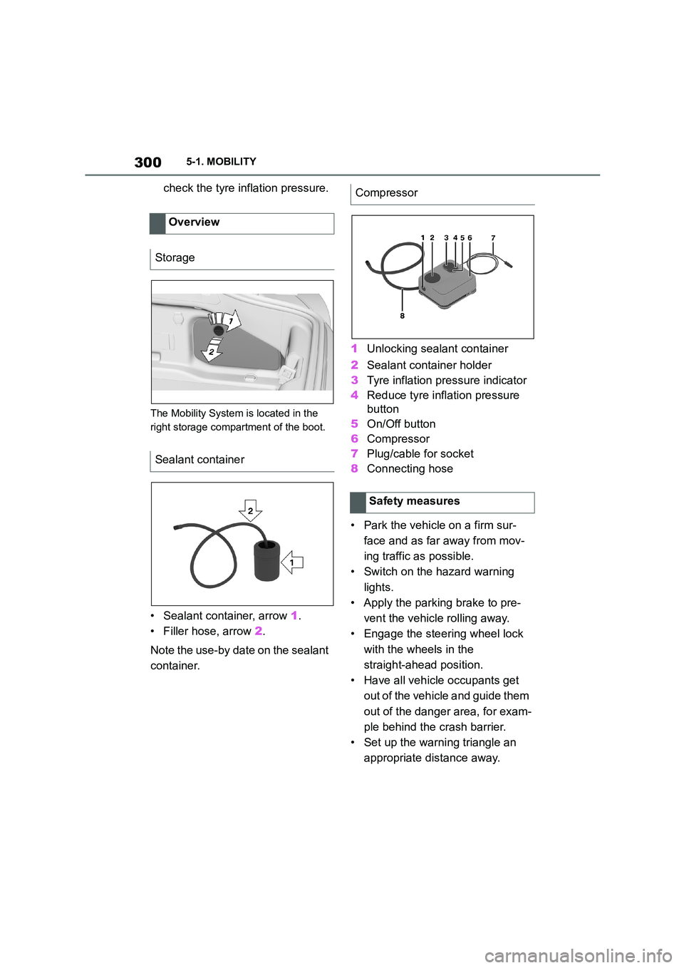
The Mobility System is located in the
right storage compartment of the boot.
• Sealant container, arrow 1.
• Filler hose, arrow 2.
Note the use-by date on the sealant
container.
1 Unlocking sealant container
2 Sealant container holder
3 Tyre inflation pressure indicator
4 Reduce tyre inflation pressure
button
5 On/Off button
6 Compressor
7 Plug/cable for socket
8 Connecting hose
• Park the vehicle on a firm sur-
face and as far away from mov-
ing traffic as possible.
• Switch on the hazard warning
lights.
• Apply the parking brake to pre-
vent the vehicle rolling away.
• Engage the steering wheel lock
with the wheels in the
straight-ahead position.
• Have all vehicle occupants get
out of the vehicle and guide them
out of the danger area, for exam-
ple behind the crash barrier.
• Set up the warning triangle an
appropriate distance away.
Overview
Storage
Sealant container
Compressor
Safety measures