2022 TOYOTA SUPRA transmission
[x] Cancel search: transmissionPage 160 of 498
1583-1. CONTROLS
■Gearshift
Gear shifting is only carried out at
the appropriate engine RPM and
vehicle speed.
■Short-term manual operation
In selector lever position D, operat-
ing a shift paddle causes the sys-
tem to switch to manual operation
temporarily.
The gearbox reverts to automatic
operation from manual operation
after a certain period of time of
moderate driving without accelera-
tion or gear shifts using the shift
paddles.
Changing to automatic operation is
possible as follows:
Pull and hold the right shift pad-
dle until D is shown in the instru-
ment cluster.
In addition to pulling the right
shift paddle, pull the left shift
paddle.
■Permanent manual operation
In selector lever position M, operat-
ing a shift paddle causes the sys-
tem to switch permanently to
manual operation (mode).
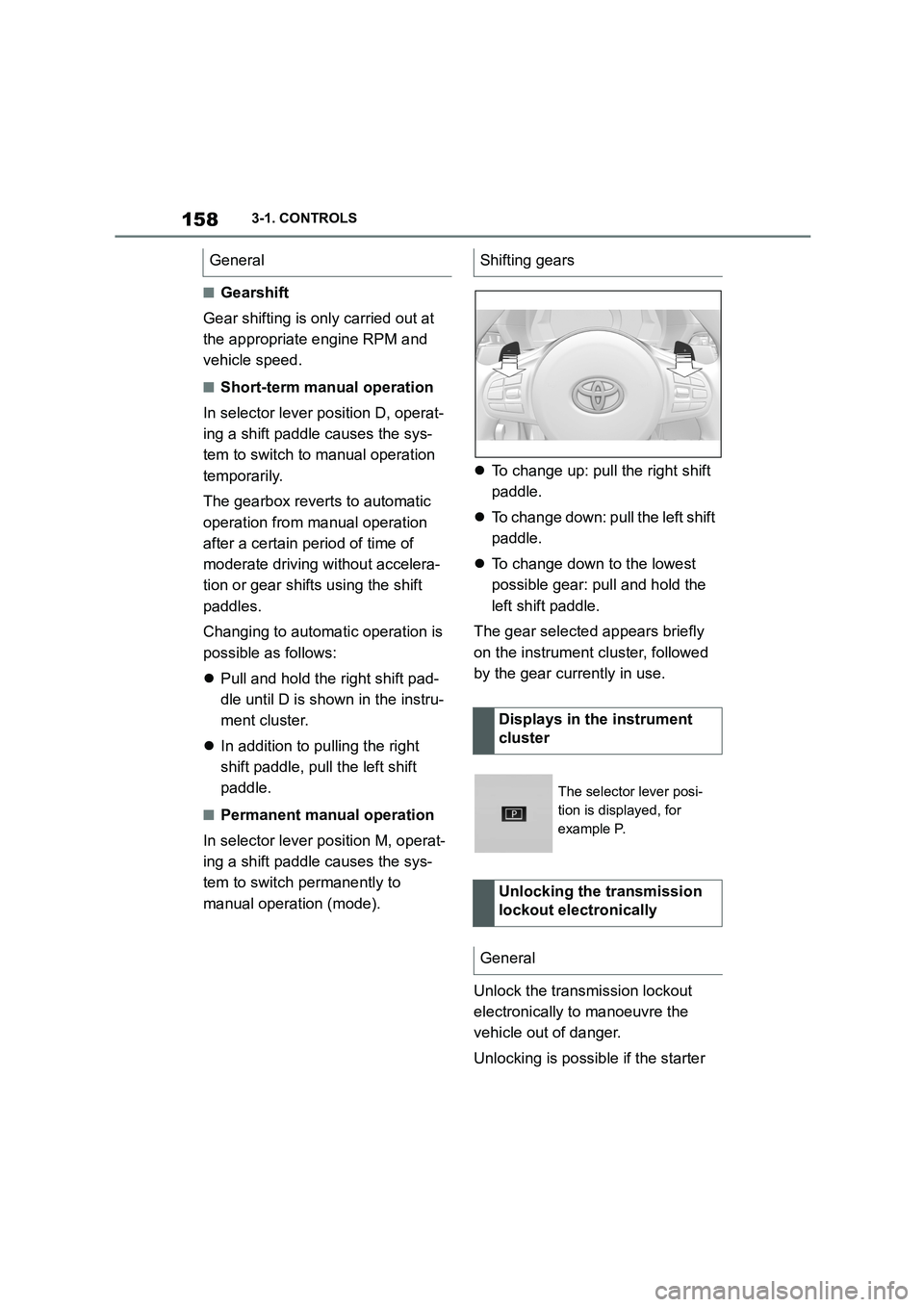
To change up: pull the right shift
paddle.
To change down: pull the left shift
paddle.
To change down to the lowest
possible gear: pull and hold the
left shift paddle.
The gear selected appears briefly
on the instrument cluster, followed
by the gear currently in use.
Unlock the transmission lockout
electronically to manoeuvre the
vehicle out of danger.
Unlocking is possible if the starter
GeneralShifting gears
Displays in the instrument
cluster
The selector lever posi-
tion is displayed, for
example P.
Unlocking the transmission
lockout electronically
General
Page 161 of 498
159
3
3-1. CONTROLS
CONTROLS
can turn the engine.
Before the transmission lockout is
released, apply the parking brake
to prevent the ve hicle from rolling
away.
1 Apply the brakes and keep them
applied.
2 Press the start/stop button. The
starter must be heard to start
turning. Press and hold the
start/stop button.
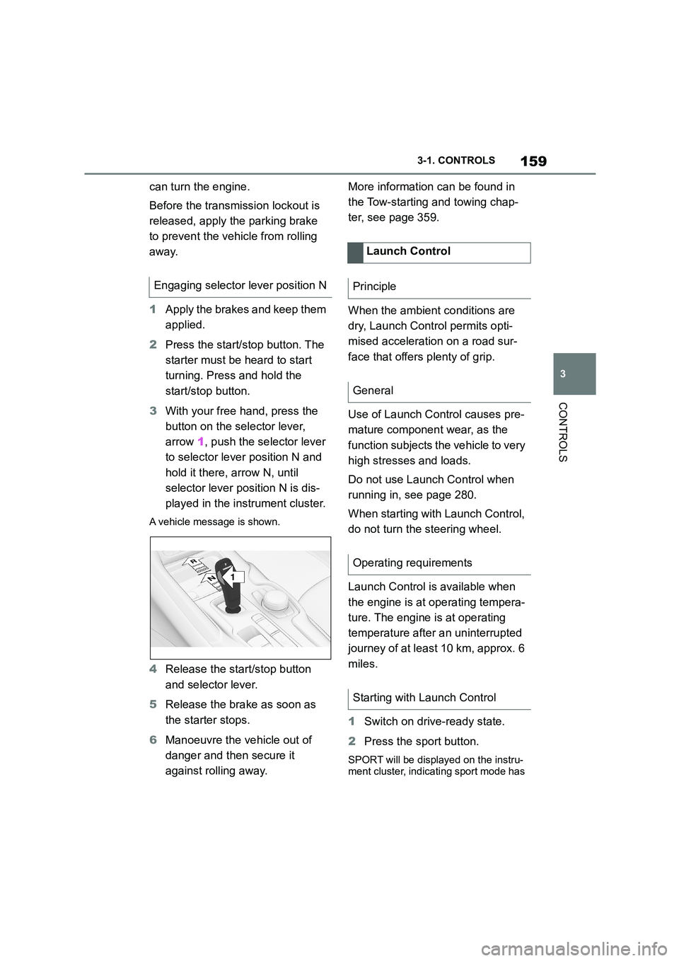
3 With your free hand, press the
button on the selector lever,
arrow 1, push the selector lever
to selector lever position N and
hold it there, arrow N, until
selector lever position N is dis-
played in the instrument cluster.
A vehicle message is shown.
4 Release the start/stop button
and selector lever.
5 Release the brake as soon as
the starter stops.
6 Manoeuvre the vehicle out of
danger and then secure it
against rolling away.
More information can be found in
the Tow-starting and towing chap-
ter, see page 359.
When the ambient conditions are
dry, Launch Control permits opti-
mised acceleration on a road sur-
face that offers plenty of grip.
Use of Launch Control causes pre-
mature component wear, as the
function subjects t he vehicle to very
high stresses and loads.
Do not use Launch Control when
running in, see page 280.
When starting with Launch Control,
do not turn the steering wheel.
Launch Control is available when
the engine is at operating tempera-
ture. The engine is at operating
temperature after an uninterrupted
journey of at least 10 km, approx. 6
miles.
1 Switch on drive-ready state.
2 Press the sport button.
SPORT will be displayed on the instru-
ment cluster, indicating sport mode has
Engaging selector lever position N
1
R
N
Launch Control
Principle
General
Operating requirements
Starting with Launch Control
Page 162 of 498
1603-1. CONTROLS
been selected.
3 Press the button.
TRACTION will be displayed on the instrument cluster and the VSC OFF
indicator lamp will illuminate.
4 Select the D selector lever posi-
tion.
5 Firmly depress the brake pedal
with your left foot.
6 Fully depress and hold the
accelerator pedal at the kick-
down position.
A flag symbol will be shown in the instrument cluster.
7 The engine speed will be
adjusted for launching. Release
the brake pedal within 3 sec-
onds.
Once Launch Control has been
used, the transmission requires
approximately 5 minutes to cool
down before Launch Control can be
used again. Launch Control adapts
to the ambient conditions when
used again.
To support driving stability, re-acti-
vate Vehicle Stab ility Control, VSC
as soon as possible.
An experienced driver may be able
to achieve better acceleration val-
ues in VSC OFF mode.
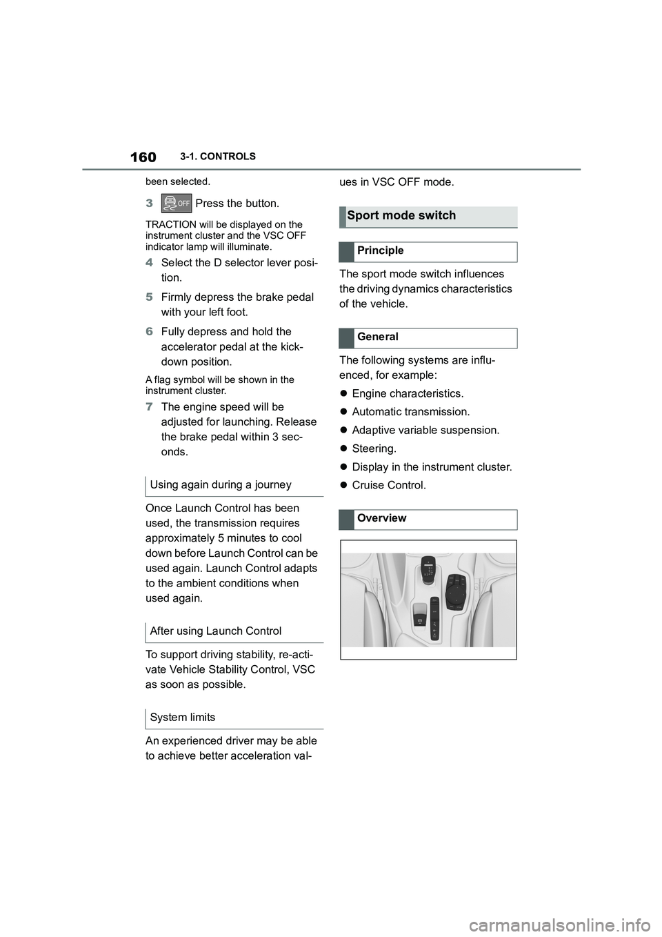
The sport mode switch influences
the driving dynamics characteristics
of the vehicle.
The following systems are influ-
enced, for example:
Engine characteristics.
Automatic transmission.
Adaptive variable suspension.
Steering.
Display in the instrument cluster.
Cruise Control. Using again during a journey
After using Launch Control
System limits
Sport mode switch
Principle
General
Overview
Page 170 of 498
1683-1. CONTROLS
The current fill level of the fuel tank
is displayed.
The angle of the vehicle may cause
the display to fluctuate.
For notes on refuelling, see page
290.
It is vital to avoid engine speeds in
the red warning zone. In this zone,
the fuel supply is interrupted to pro-
tect the engine.
Depending on the equipment, the
shift lights on the revolution counter
indicate the maximum shift point at
which the best possible accelera-
tion can be achieved.
When the selected driving mode is
sport mode, a shift light will be dis-
played.
1 Select SPORT using the sport
mode switch.
2 Activate manual mode of the
transmission.
Automatic high-beam
Automatic high-beams
switched on.
The high-beam head-
lights are switched on and
off automatically depend-
ing on the traffic situation.
Automatic high-beam, see
page 188.
Blue lights
High-beam headlights
The high-beam head-
lights are switched on.
High-beam headlights,
see page 150.
Fuel gauge
Principle
General
Display
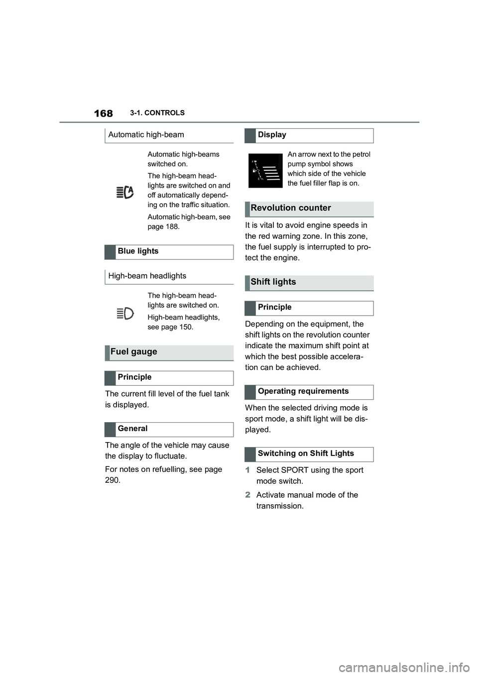
An arrow next to the petrol
pump symbol shows
which side of the vehicle
the fuel filler flap is on.
Revolution counter
Shift lights
Principle
Operating requirements
Switching on Shift Lights
Page 173 of 498
171
3
3-1. CONTROLS
CONTROLS
2 "Vehicle status"
3 "Service requirements"
4 "Date:"
5 Select the desired setting.
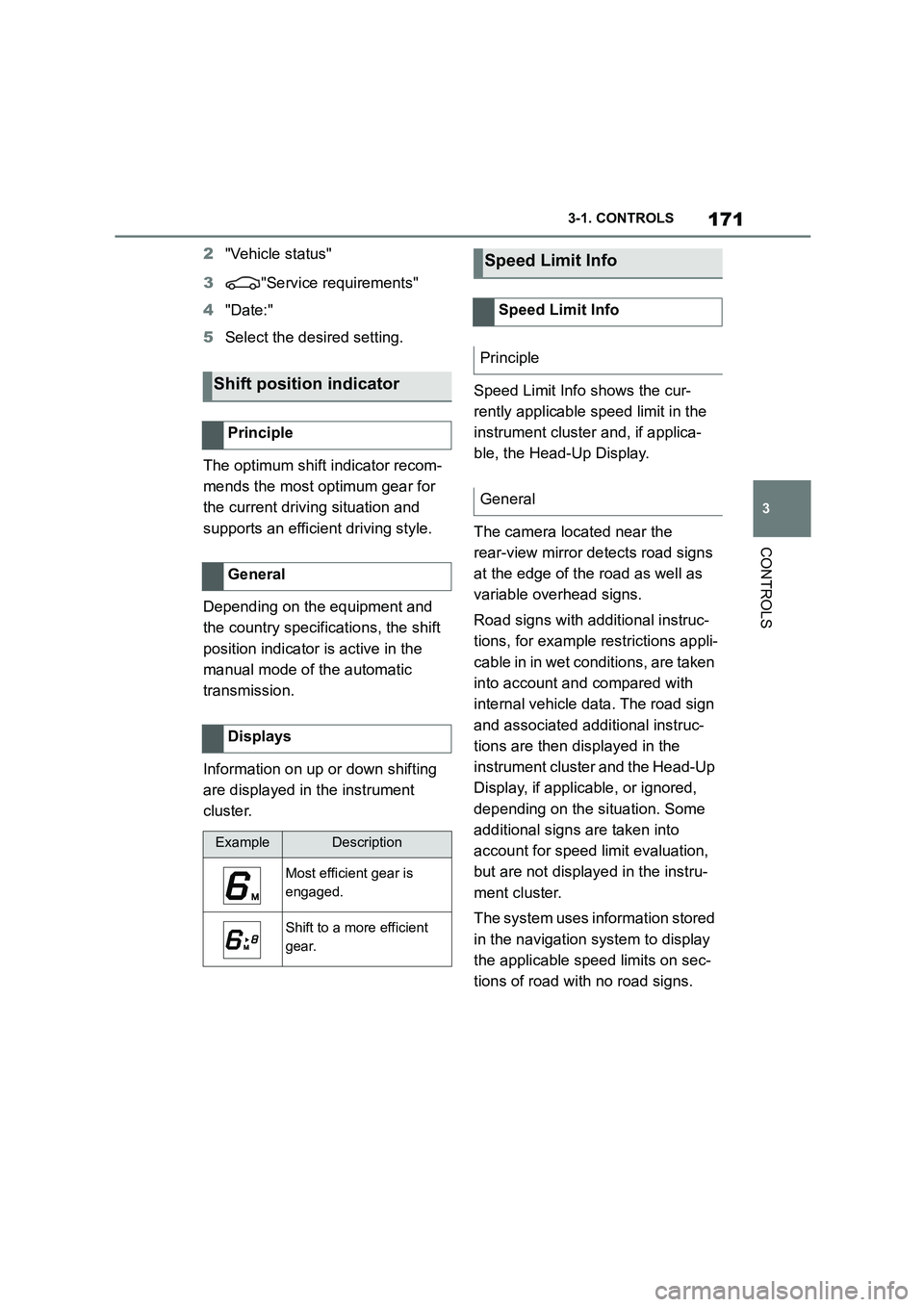
The optimum shift indicator recom-
mends the most optimum gear for
the current driving situation and
supports an efficient driving style.
Depending on the equipment and
the country specifications, the shift
position indicator is active in the
manual mode of the automatic
transmission.
Information on up or down shifting
are displayed in the instrument
cluster.
Speed Limit Info shows the cur-
rently applicable speed limit in the
instrument cluster and, if applica-
ble, the Head-Up Display.
The camera located near the
rear-view mirror detects road signs
at the edge of the road as well as
variable overhead signs.
Road signs with additional instruc-
tions, for example restrictions appli-
cable in in wet conditions, are taken
into account and compared with
internal vehicle data. The road sign
and associated additional instruc-
tions are then displayed in the
instrument cluster and the Head-Up
Display, if applic able, or ignored,
depending on the situation. Some
additional signs are taken into
account for speed limit evaluation,
but are not displayed in the instru-
ment cluster.
The system uses information stored
in the navigation system to display
the applicable speed limits on sec-
tions of road with no road signs.
Shift position indicator
Principle
General
Displays
ExampleDescription
Most efficient gear is
engaged.
Shift to a more efficient
gear.
Speed Limit Info
Speed Limit Info
Principle
General
Page 235 of 498
233
3
3-1. CONTROLS
CONTROLS
The current speed is adopted as
the speed limit.
When switching on at a standstill or
driving at low speed, 30 km/h/20
mph is set as the speed limit.
When activating the speed limit it is
possible that Vehicle Stability Con-
trol VSC will be switched on and
the drive mode switched to NOR-
MAL.
The system switches off automati-
cally in the followi ng situations, for
example:
When switching the engine off.
When switching on Cruise Con-
trol.
When activating sport mode
using the sport mode switch.
The displays turn off.
The system is interrupted when
reverse gear is engaged or the
transmission is in neutral.
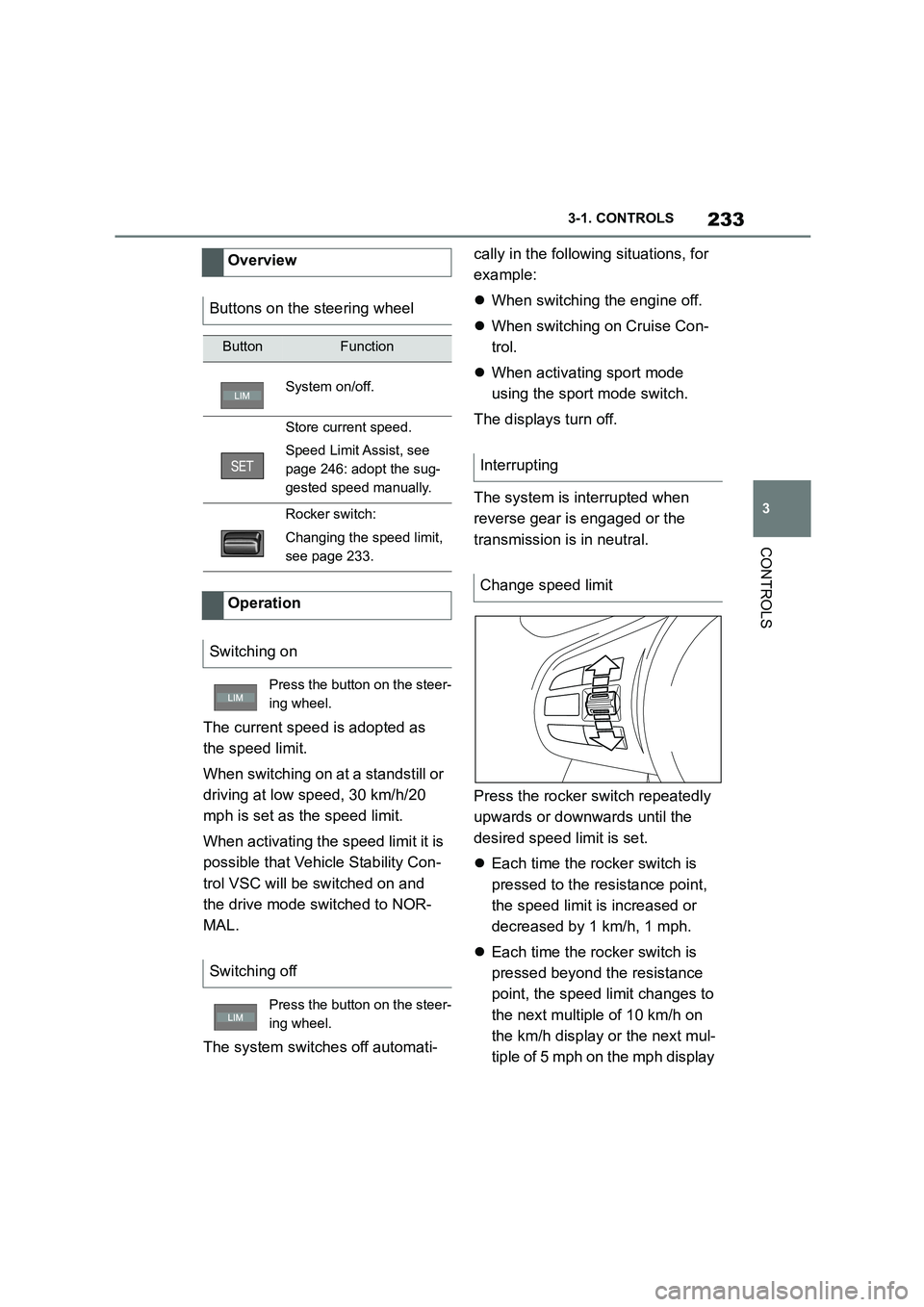
Press the rocker switch repeatedly
upwards or downwards until the
desired speed limit is set.
Each time the rocker switch is
pressed to the resistance point,
the speed limit is increased or
decreased by 1 km/h, 1 mph.
Each time the rocker switch is
pressed beyond the resistance
point, the speed limit changes to
the next multiple of 10 km/h on
the km/h display or the next mul-
tiple of 5 mph on the mph display
Overview
Buttons on the steering wheel
ButtonFunction
System on/off.
Store current speed.
Speed Limit Assist, see
page 246: adopt the sug-
gested speed manually.
Rocker switch:
Changing the speed limit,
see page 233.
Operation
Switching on
Press the button on the steer-
ing wheel.
Switching off
Press the button on the steer-
ing wheel.
Interrupting
Change speed limit
Page 286 of 498
2844-1. DRIVING HINTS
This situation, known as aquaplan-
ing, means that the tyre can actu-
ally lose contact completely with
the road surface and the vehicle
can neither be steered, nor the
brakes properly applied.
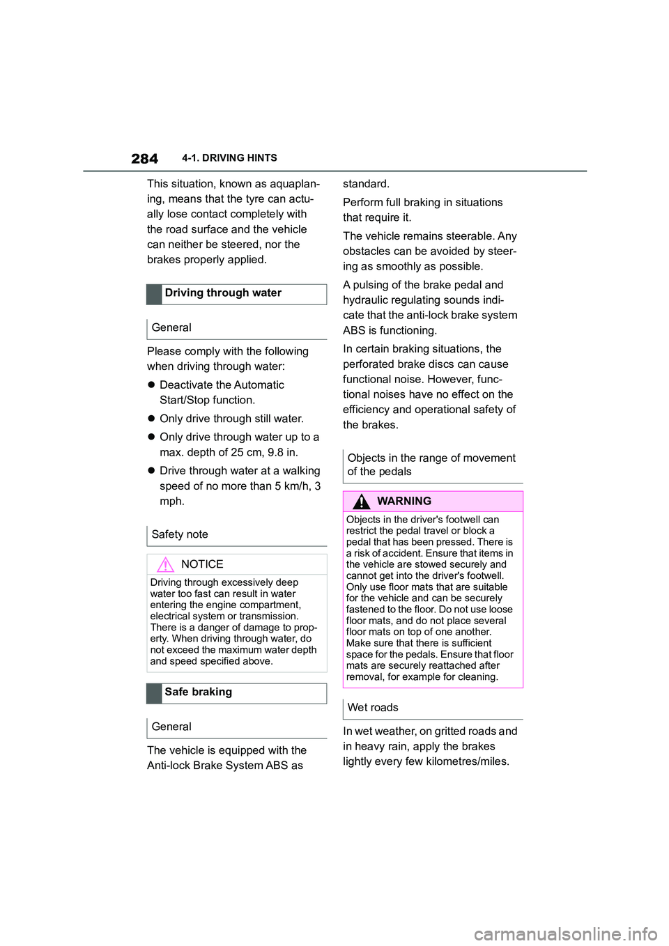
Please comply with the following
when driving through water:
Deactivate the Automatic
Start/Stop function.
Only drive through still water.
Only drive through water up to a
max. depth of 25 cm, 9.8 in.
Drive through water at a walking
speed of no more than 5 km/h, 3
mph.
The vehicle is equipped with the
Anti-lock Brake System ABS as
standard.
Perform full brakin g in situations
that require it.
The vehicle remains steerable. Any
obstacles can be avoided by steer-
ing as smoothly as possible.
A pulsing of the brake pedal and
hydraulic regulating sounds indi-
cate that the anti-lock brake system
ABS is functioning.
In certain braking situations, the
perforated brake discs can cause
functional noise. However, func-
tional noises have no effect on the
efficiency and operational safety of
the brakes.
In wet weather, on gritted roads and
in heavy rain, apply the brakes
lightly every few kilometres/miles.
Driving through water
General
Safety note
NOTICE
Driving through excessively deep water too fast can result in water
entering the engine compartment,
electrical system or transmission. There is a danger of damage to prop-
erty. When driving through water, do
not exceed the maximum water depth and speed specified above.
Safe braking
General
Objects in the range of movement
of the pedals
WA R N I N G
Objects in the driver's footwell can
restrict the pedal travel or block a
pedal that has been pressed. There is a risk of accident. Ensure that items in
the vehicle are stowed securely and
cannot get into the driver's footwell. Only use floor mats that are suitable
for the vehicle and can be securely
fastened to the floor. Do not use loose floor mats, and do not place several
floor mats on top of one another.
Make sure that there is sufficient space for the pedals. Ensure that floor
mats are securely reattached after
removal, for example for cleaning.
Wet roads
Page 377 of 498
375
6
6-1. REFERENCE
REFERENCE
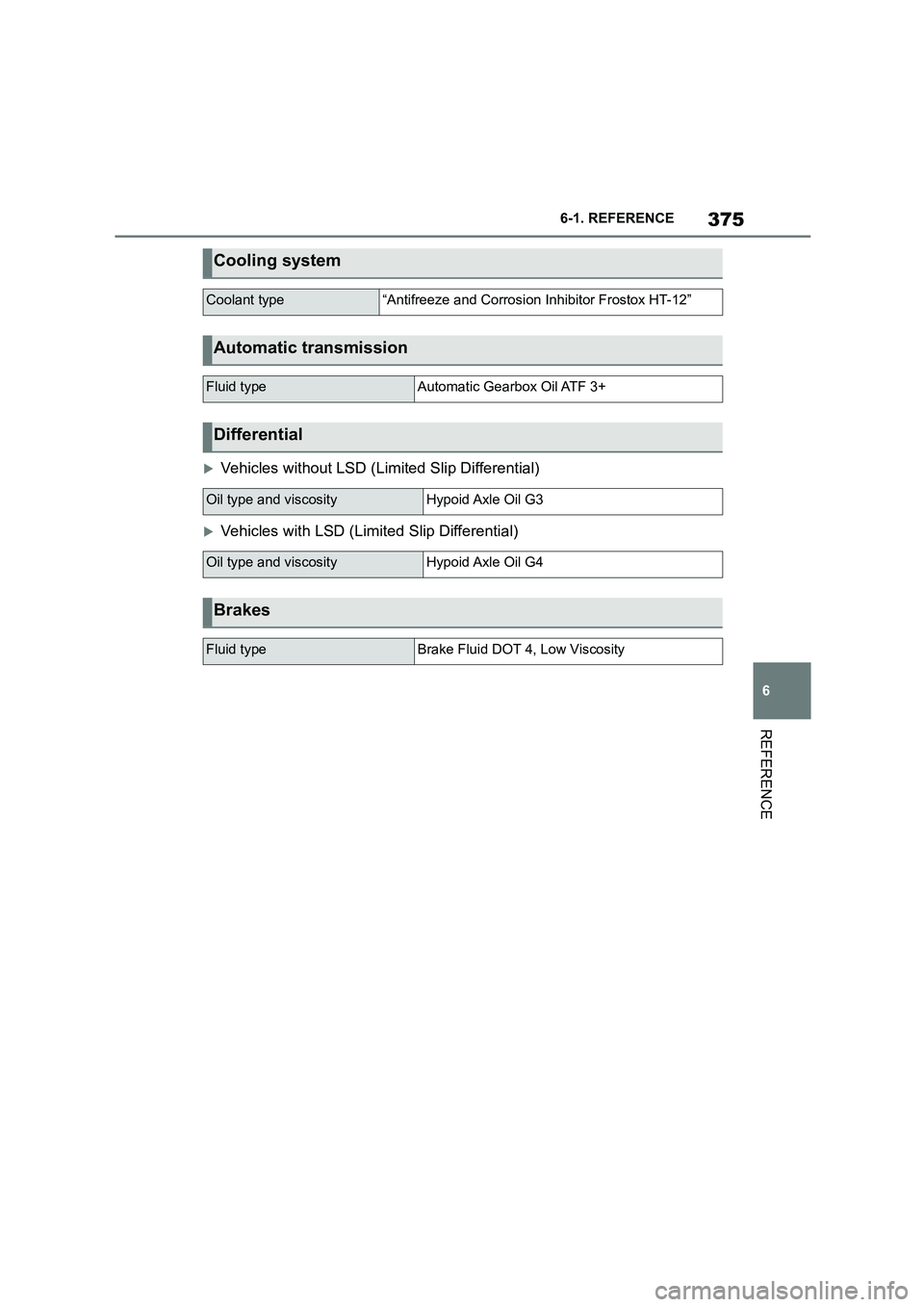
Vehicles without LSD (Limited Slip Differential)
Vehicles with LSD (Limited Slip Differential)
Cooling system
Coolant type“Antifreeze and Corrosion Inhibitor Frostox HT-12”
Automatic transmission
Fluid typeAutomatic Gearbox Oil ATF 3+
Differential
Oil type and viscosityHypoid Axle Oil G3
Oil type and viscosityHypoid Axle Oil G4
Brakes
Fluid typeBrake Fluid DOT 4, Low Viscosity