Page 277 of 356
2775-1. MOBILITY
5
MOBILITY
safe place, such as behind a
guardrail.
• If necessary, set up a warning triangle at an appropriate dis-
tance.
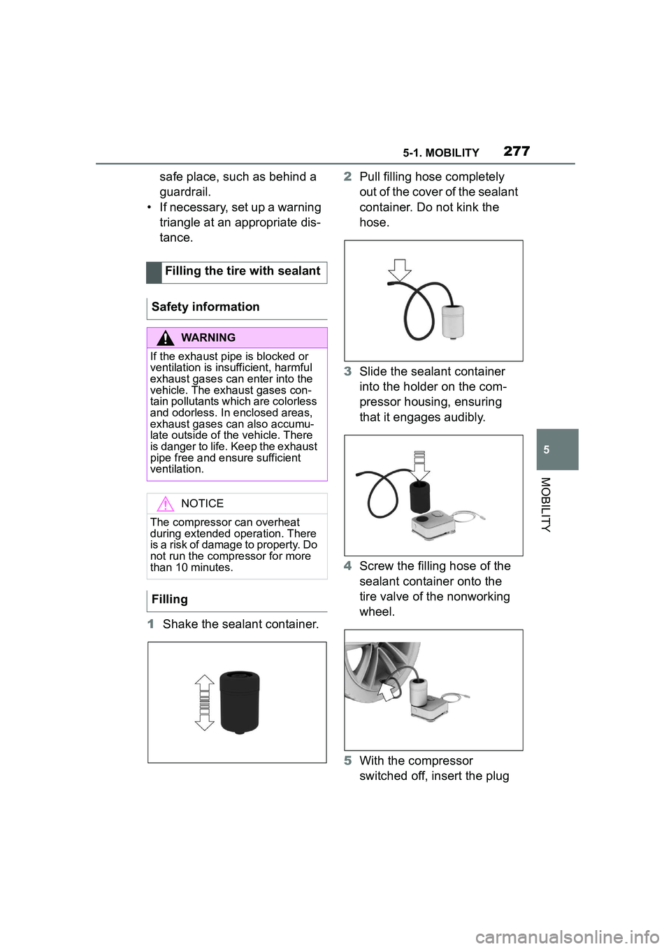
1 Shake the sealant container. 2
Pull filling hose completely
out of the cover of the sealant
container. Do not kink the
hose.
3 Slide the sealant container
into the holder on the com-
pressor housing, ensuring
that it engages audibly.
4 Screw the filling hose of the
sealant container onto the
tire valve of the nonworking
wheel.
5 With the compressor
switched off, insert the plug
Filling the tire with sealant
Safety information
WARNING
If the exhaust pipe is blocked or
ventilation is insu fficient, harmful
exhaust gases can enter into the
vehicle. The exhaust gases con-
tain pollutants which are colorless
and odorless. In enclosed areas,
exhaust gases can also accumu-
late outside of the vehicle. There
is danger to life. Keep the exhaust
pipe free and ensure sufficient
ventilation.
NOTICE
The compressor can overheat
during extended operation. There
is a risk of damage to property. Do
not run the compressor for more
than 10 minutes.
Filling
Page 278 of 356
2785-1. MOBILITY
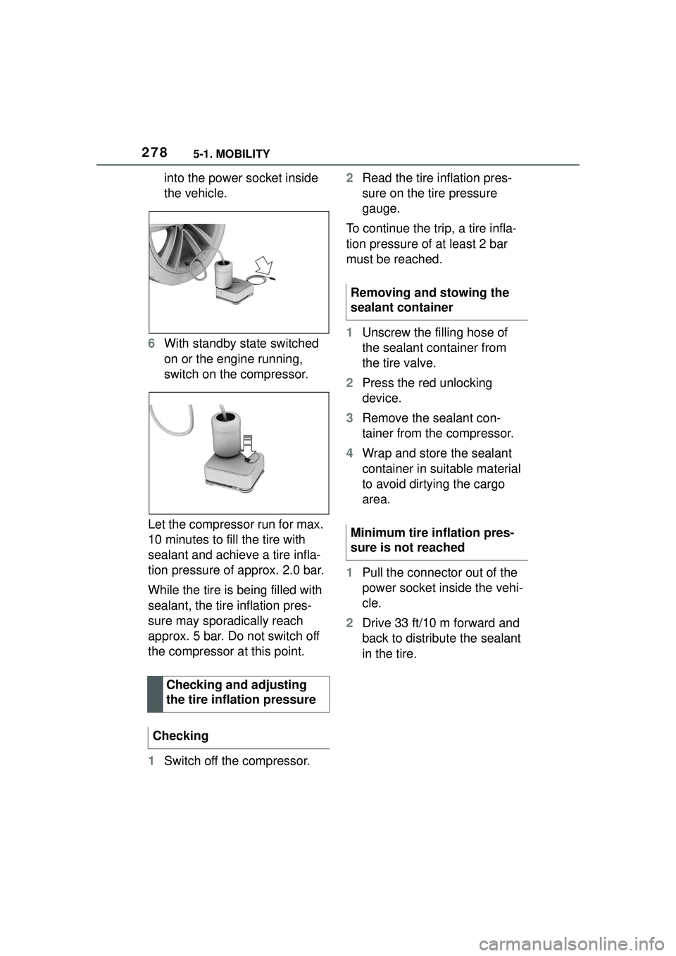
into the power socket inside
the vehicle.
6 With standby state switched
on or the engine running,
switch on the compressor.
Let the compressor run for max.
10 minutes to fill the tire with
sealant and achieve a tire infla-
tion pressure of approx. 2.0 bar.
While the tire is being filled with
sealant, the tire inflation pres-
sure may sporadically reach
approx. 5 bar. Do not switch off
the compressor at this point.
1 Switch off the compressor. 2
Read the tire inflation pres-
sure on the tire pressure
gauge.
To continue the trip, a tire infla-
tion pressure of at least 2 bar
must be reached.
1 Unscrew the filling hose of
the sealant container from
the tire valve.
2 Press the red unlocking
device.
3 Remove the sealant con-
tainer from the compressor.
4 Wrap and store the sealant
container in suitable material
to avoid dirtying the cargo
area.
1 Pull the connector out of the
power socket inside the vehi-
cle.
2 Drive 33 ft/10 m forward and
back to distribute the sealant
in the tire.
Checking and adjusting
the tire inflation pressure
Checking
Removing and stowing the
sealant container
Minimum tire inflation pres-
sure is not reached
Page 289 of 356
2895-1. MOBILITY
5
MOBILITY
or wheels on the vehicle that
prevent the TPMS from func-
tioning properly. Always
check the TPMS malfunction
telltale after replacing one or
more tires or wheels on your
vehicle to ensure that the
replacement or alternate tires
and wheels allow the TPMS
to continue to function prop-
erly.
If a tire is punctured and loses
pressure, it is not necessary to
replace the tire immediately if a
tire repair kit (Mobility System) is
used.
If needed, the tools for changing
wheels are available as acces-
sories from your Toyota dealer.
*: if equipped
The wheel lug bolts have a spe-
cial coding. The lug bolts can
only be released with the
adapter which matches the cod-
ing.
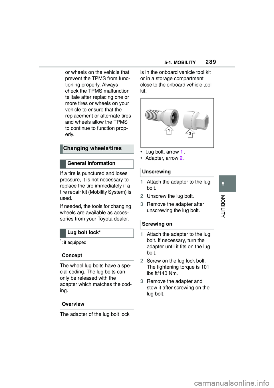
The adapter of the lug bolt lock is in the onboard vehicle tool kit
or in a storage compartment
close to the onboard vehicle tool
kit.
• Lug bolt, arrow
1.
• Adapter, arrow 2.
1 Attach the adapter to the lug
bolt.
2 Unscrew the lug bolt.
3 Remove the adapter after
unscrewing the lug bolt.
1 Attach the adapter to the lug
bolt. If necessary, turn the
adapter until it fits on the lug
bolt.
2 Screw on the lug lock bolt.
The tightening torque is 101
lbs ft/140 Nm.
3 Remove the adapter and
stow it after screwing on the
lug bolt.
Changing wheels/tires
General information
Lug bolt lock*
Concept
Overview
Unscrewing
Screwing on
Page 292 of 356

2925-1. MOBILITY
1Pull lever, arrow 1.
Hood is unlocked.
2After the lever is released,
pull the lever again, arrow 2.
Hood can be opened.
3Be careful of protruding parts
on the hood.
Energetically close the hood
from approx. 20 in/50 cm.
The hood must engage on both
sides.
WARNING
There are protruding parts, for
instance locking hook, on the
inside of the hood. There is a risk
of injury. If the hood is open, pay
attention to protruding parts and
keep clear of these areas.
WARNING
An incorrectly locked hood can
open while driving and restrict vis-
ibility. There is a risk of an acci-
dent. Stop immediately and
correctly close the hood.
WARNING
Body parts can be jammed when
opening and closing the hood.
There is a risk of injury. Make sure
that the area of movement of the
hood is clear during opening and
closing.
NOTICE
Folded-away wipers can be
jammed when the hood is
opened. There is a risk of damage
to property. Make sure that the
wipers with the wiper blades
mounted are folded down onto the
windshield before opening the
hood.
Opening
Closing
Page 297 of 356
2975-1. MOBILITY
5
MOBILITY
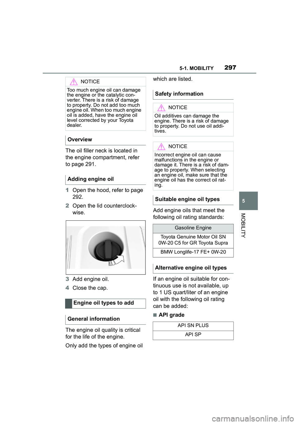
The oil filler neck is located in
the engine compartment, refer
to page 291.
1Open the hood, refer to page
292.
2 Open the lid counterclock-
wise.
3 Add engine oil.
4 Close the cap.
The engine oil quality is critical
for the life of the engine.
Only add the types of engine oil which are listed.
Add engine oils that meet the
following oil rating standards:
If an engine oil suitable for con-
tinuous use is not available, up
to 1 US quart/liter of an engine
oil with the following oil rating
can be added:
■API grade
NOTICE
Too much engine oil can damage
the engine or the catalytic con-
verter. There is a risk of damage
to property. Do not add too much
engine oil. When too much engine
oil is added, have the engine oil
level corrected by your Toyota
dealer.
Overview
Adding engine oil
Engine oil types to add
General information
Safety information
NOTICE
Oil additives can damage the
engine. There is a risk of damage
to property. Do not use oil addi-
tives.
NOTICE
Incorrect engine oil can cause
malfunctions in the engine or
damage it. There is a risk of dam-
age to property. When selecting
an engine oil, make sure that the
engine oil has the correct oil rat-
ing.
Suitable engine oil types
Gasoline Engine
Toyota Genuine Motor Oil SN
0W-20 C5 for GR Toyota Supra
BMW Longlife-17 FE+ 0W-20
Alternative engine oil types
API SN PLUS
API SP
Page 299 of 356
2995-1. MOBILITY
5
MOBILITY
ervoirs in the engine compart-
ment. Check and top up the
coolant levels on a regular
basis.
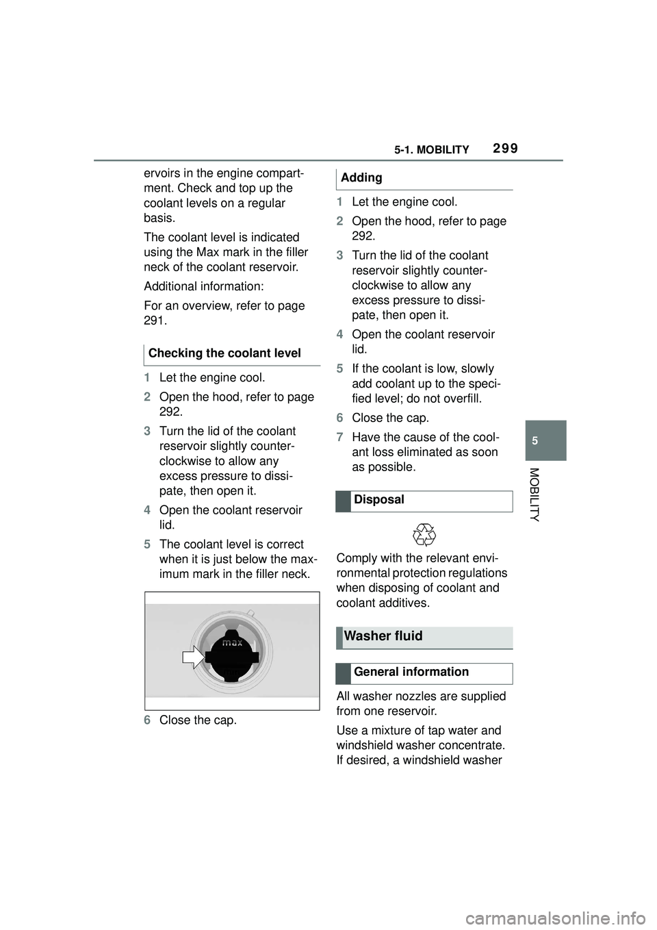
The coolant level is indicated
using the Max mark in the filler
neck of the coolant reservoir.
Additional information:
For an overview, refer to page
291.
1Let the engine cool.
2 Open the hood, refer to page
292.
3 Turn the lid of the coolant
reservoir slightly counter-
clockwise to allow any
excess pressure to dissi-
pate, then open it.
4 Open the coolant reservoir
lid.
5 The coolant level is correct
when it is just below the max-
imum mark in the filler neck.
6 Close the cap. 1
Let the engine cool.
2 Open the hood, refer to page
292.
3 Turn the lid of the coolant
reservoir slightly counter-
clockwise to allow any
excess pressure to dissi-
pate, then open it.
4 Open the coolant reservoir
lid.
5 If the coolant is low, slowly
add coolant up to the speci-
fied level; do not overfill.
6 Close the cap.
7 Have the cause of the cool-
ant loss eliminated as soon
as possible.
Comply with the relevant envi-
ronmental protection regulations
when disposing of coolant and
coolant additives.
All washer nozzles are supplied
from one reservoir.
Use a mixture of tap water and
windshield washer concentrate.
If desired, a windshield washer
Checking the coolant levelAdding
Disposal
Washer fluid
General information
Page 302 of 356
3025-1. MOBILITY
Please consult “Owner's War-
ranty Information Booklet” or
“Owner's Manual Supplement”
for additional information on ser-
vice and maintenance work.
The manufacturer of your vehi-
cle recommends that mainte-
nance and repair be performed
by a Toyota dealer. Records of
regular maintenance and repair
work should be retained.
Scheduled maintenance should
be performed at specified inter-
vals according to the mainte-
nance schedule.
For details about maintenance
items and schedules, refer to
the "Scheduled Maintenance
Guide" or "Owner's Manual Sup-
plement".
Devices connected to the OBD
socket trigger the alarm system
when the vehicle is locked.
Remove any devices con-
nected at the OBD socket before locking the vehicle.
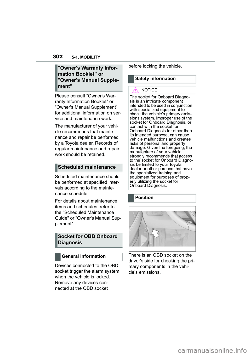
There is an OBD socket on the
driver's side for checking the pri-
mary components in the vehi-
cle's emissions.
"Owner's Warranty Infor-
mation Booklet" or
"Owner's Manual Supple-
ment"
Scheduled maintenance
Socket for OBD Onboard
Diagnosis
General information
Safety information
NOTICE
The socket for Onboard Diagno-
sis is an intricate component
intended to be used in conjunction
with specialized equipment to
check the vehicle’s primary emis-
sions system. Improper use of the
socket for Onboard Diagnosis, or
contact with the socket for
Onboard Diagnosis for other than
its intended purpose, can cause
vehicle malfunctions and creates
risks of personal and property
damage. Given the foregoing, the
manufacture of your vehicle
strongly recommends that access
to the socket for Onboard Diagno-
sis be limited to your Toyota
dealer or other persons that have
the specialized training and
equipment for purposes of prop-
erly utilizing the socket for
Onboard Diagnosis.
Position
Page 303 of 356
3035-1. MOBILITY
5
MOBILITY
This chapter describes all stan-
dard, country-specific and
optional features offered with
the series. It also describes fea-
tures and functions that are not
necessarily available in your
vehicle, e.g., due to the selected
options or country versions. This
also applies to safety-related
functions and systems. When
using these functions and sys-
tems, the applicable laws and
regulations must be observed.
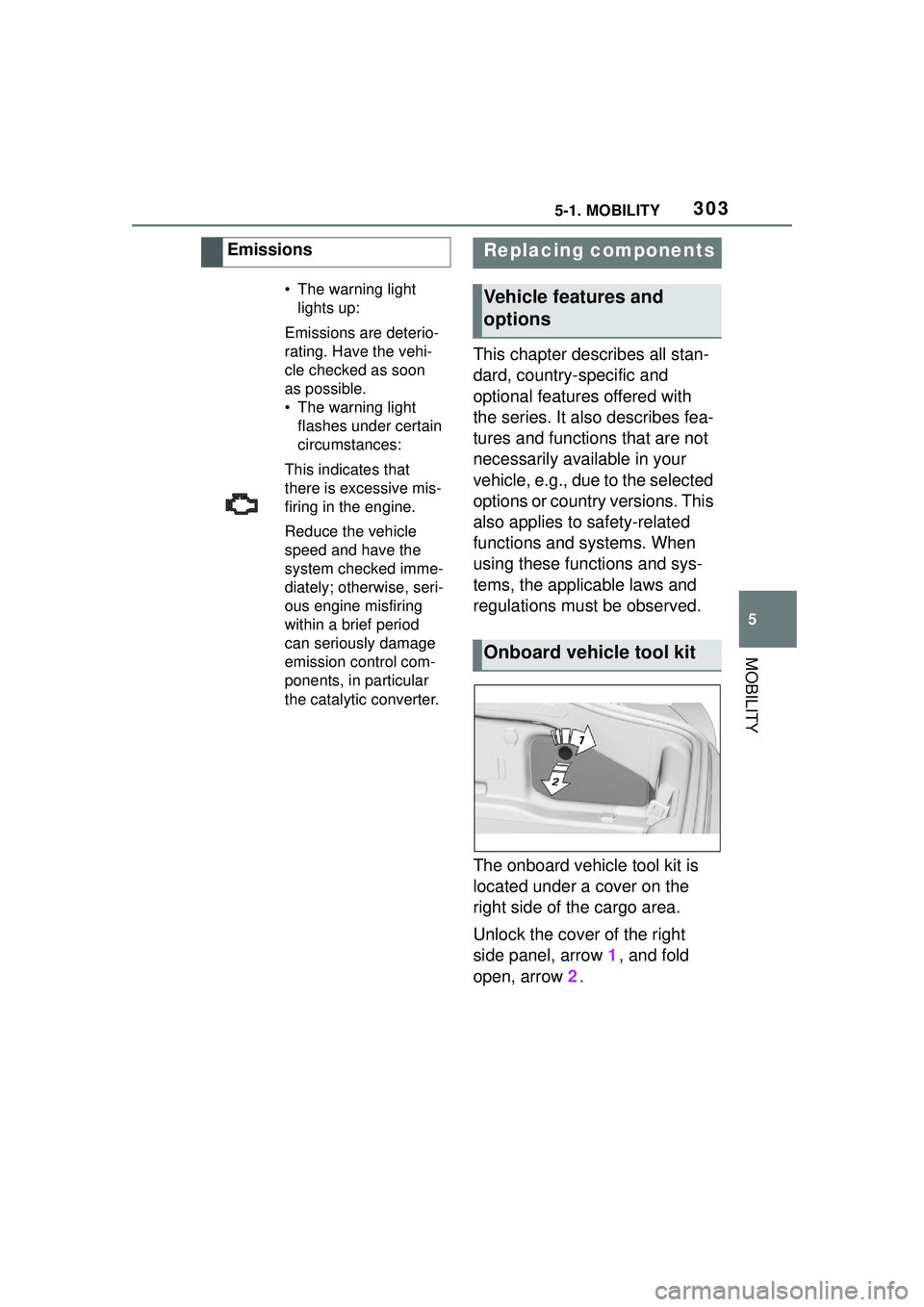
The onboard vehicle tool kit is
located under a cover on the
right side of the cargo area.
Unlock the cover of the right
side panel, arrow 1, and fold
open, arrow 2.
Emissions
• The warning light
lights up:
Emissions are deterio-
rating. Have the vehi-
cle checked as soon
as possible.
• The warning light flashes under certain
circumstances:
This indicates that
there is excessive mis-
firing in the engine.
Reduce the vehicle
speed and have the
system checked imme-
diately; otherwise, seri-
ous engine misfiring
within a brief period
can seriously damage
emission control com-
ponents, in particular
the catalytic converter.
Replacing components
Vehicle features and
options
Onboard vehicle tool kit