Page 126 of 356
1263-1. CONTROLS
3Wipers return to their resting
position and are ready again
for operation.
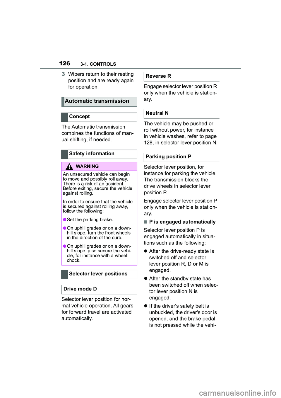
The Automatic transmission
combines the functions of man-
ual shifting, if needed.
Selector lever position for nor-
mal vehicle operation. All gears
for forward travel are activated
automatically. Engage selector lever position R
only when the vehicle is station-
ary.
The vehicle may be pushed or
roll without power, for instance
in vehicle washes, refer to page
128, in selector lever position N.
Selector lever position, for
instance for parking the vehicle.
The transmission blocks the
drive wheels in selector lever
position P.
Engage selector lever position P
only when the vehicle is station-
ary.
■P is engaged automatically
Selector lever position P is
engaged automatically in situa-
tions such as the following:
After the drive-ready state is
switched off and selector
lever position R, D or M is
engaged.
After the standby state has
been switched off when selec-
tor lever position N is
engaged.
If the driver's safety belt is
unbuckled, the driver's door is
opened, and the brake pedal
is not pressed while the vehi-
Automatic transmission
Concept
Safety information
WARNING
An unsecured vehicle can begin
to move and possibly roll away.
There is a risk of an accident.
Before exiting, secure the vehicle
against rolling.
In order to ensure that the vehicle
is secured against rolling away,
follow the following:
●Set the parking brake.
●On uphill grades or on a down-
hill slope, turn the front wheels
in the direction of the curb.
●On uphill grades or on a down-
hill slope, also secure the vehi-
cle, for instance with a wheel
chock.
Selector lever positions
Drive mode D
Reverse R
Neutral N
Parking position P
Page 134 of 356
1343-1. CONTROLS
The display can be changed for
sport mode.
The driving mode will change to
sport mode.
The vehicle messages system
monitors functions in the vehicle
and notifies you of malfunctions
in the monitored systems.
A vehicle messages message is
displayed as a combination of
indicator or warning lights and
SMS text messages in the
instrument cluster and, if appli-
cable, in the Head-up Display.
In addition, an acoustic signal
may sound and an SMS text
message may appear on the
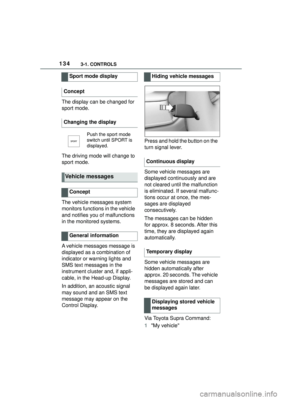
Control Display.Press and hold the button on the
turn signal lever.
Some vehicle messages are
displayed continuously and are
not cleared until the malfunction
is eliminated. If several malfunc-
tions occur at once, the mes-
sages are displayed
consecutively.
The messages can be hidden
for approx. 8 seconds. After this
time, they are displayed again
automatically.
Some vehicle messages are
hidden automatically after
approx. 20 seconds. The vehicle
messages are stored and can
be displayed again later.
Via Toyota Supra Command:
1
"My vehicle"
Sport mode display
Concept
Changing the display
Push the sport mode
switch until SPORT is
displayed.
Vehicle messages
Concept
General information
Hiding vehicle messages
Continuous display
Temporary display Displaying stored vehicle
messages
Page 135 of 356
1353-1. CONTROLS
3
CONTROLS
2"Vehicle status"
3 "Vehicle messages"
4 Select the SMS text mes-
sage.
SMS text messages in combina-
tion with a symbol in the instru-
ment cluster explain a vehicle
message and the meaning of
the indicator/warning lights.
Additional information, such as
the reason for an error or mal-
function or the required action,
can be called up via vehicle
messages.
With urgent messages the
added text will be automatically
displayed on the Control Dis-
play.
Depending on the vehicle mes-
sage, further help can be
selected.
Via Toyota Supra Command:
1 "My vehicle" 2
"Vehicle status"
3 "Vehicle messages"
4 Select the desired text mes-
sage.
5 Select desired setting
Certain messages displayed
while driving are displayed
again after drive-ready state is
switched off.
Indicator/warning lights in the
instrument cluster display the
status of some functions in the
vehicle and indicate when a
malfunction is present in the
monitored systems.
The indicator/warning lights can
light up in a variety of combina-
tions and colors.
Several of the lights are
checked for proper functioning
and light up temporarily when
drive-ready state is switched on.
Display
Vehicle messages
At least one vehicle
messages message is
displayed or is stored.
SMS text messages
Supplementary SMS text
messages
Messages after trip comple-
tion
Indicator/warning lights
Concept
General information
Page 138 of 356

1383-1. CONTROLS
Steering system
Steering system may
not be working.
Have the system
checked by your Toyota
dealer.
Emissions
The warning light
lights up:
Emissions are deterio-
rating. Have the vehi-
cle checked as soon
as possible.
The warning light
flashes under certain
circumstances:
This indicates that
there is excessive mis-
firing in the engine.
Reduce the vehicle
speed and have the
system checked imme-
diately; otherwise, seri-
ous engine misfiring
within a brief period
can seriously damage
emission control com-
ponents, in particular
the catalytic converter.
Socket for Onboard
Diagnosis, refer to page
302.
Green lights
Turn signal
Turn signal switched
on.
Unusually rapid flash-
ing of the indicator light
indicates that a turn sig-
nal bulb has failed.
Turn signal, refer to
page 121.
Parking lights
Parking lights are
switched on.
Parking lights/low
beams, refer to page
153.
Low beams
Low beams are
switched on.
Parking lights/low
beams, refer to page
153.
Lane departure warning
The indicator light lights
up: the system is acti-
vated. A lane marking
was detected on at
least one side of the
vehicle and warnings
can be issued.
Lane departure warn-
ing, refer to page 182.
Page 139 of 356
1393-1. CONTROLS
3
CONTROLS
The current fill level of the fuel
tank is displayed.
Vehicle tilt position may cause
the display to vary.
Information on refueling, refer to
page 262.Always avoid engine speeds in
the red warning field. In this
range, the fuel supply is reduced
to protect the engine.
Depending on the vehicle equip-
ment, the shift position indica-
tors on the instrument cluster
indicates the maximum shift
point at which the best possible
acceleration can be achieved.
When the selected driving mode
is sport mode, a shift light will be
displayed.
Automatic high-beam
Automatic high-beam is
switched on.
High beams are
switched on and off
automatically depend-
ing on the traffic situa-
tion.
Automatic high-beam,
refer to page 156.
Blue lights
High beams
High beams are
switched on.
High beams, refer to
page 122.
Fuel gauge
Concept
General information
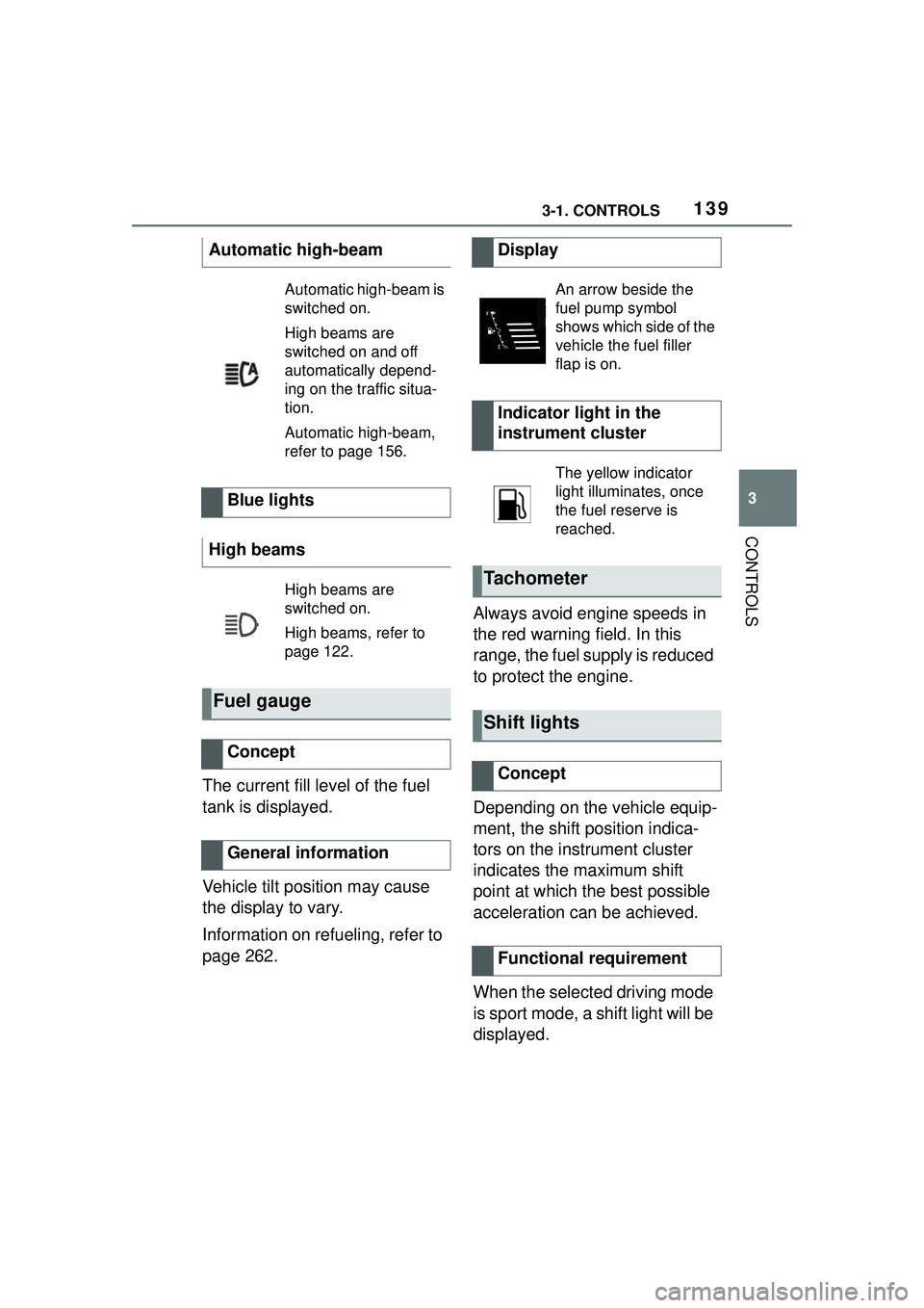
Display
An arrow beside the
fuel pump symbol
shows which side of the
vehicle the fuel filler
flap is on.
Indicator light in the
instrument cluster
The yellow indicator
light illuminates, once
the fuel reserve is
reached.
Tachometer
Shift lights
Concept
Functional requirement
Page 140 of 356

1403-1. CONTROLS
1Select SPORT using the
sport mode switch.
2 Activate manual mode of the
transmission.
• Successive orange illumi- nated fields indicate the
upcoming shift moment.
• The field lights up red. Do not wait any further to shift.
When the maximum speed is
reached, the entire display
flashes red and the supply of
fuel is interrupted in order to
protect the engine. For further information, see Idle
state, standby state, and
drive-ready state, refer to page
43.
Switching on shift lights
Display
Standby state and
drive-ready state
The lettering OFF in
the instrument cluster
indicates that
drive-ready state is
switched off and
standby state is
switched on.
The lettering READY in
the instrument cluster
indicates that the
drive-ready state is
switched on.
Engine coolant tempera-
ture
Display
When the engine
temperature is low:
Only the segments in
the low temperature
range will be illumi-
nated. Drive with
moderate engine
speed and vehicle
speed.
When the engine
temperature is nor-
mal: All segments to
the middle tempera-
ture range will be illu-
minated.
When the engine
temperature is high:
All segments to the
high temperature
range will be illumi-
nated. A warning
message will also be
displayed.
To check the coolant
level, refer to page 298.
Page 141 of 356
1413-1. CONTROLS
3
CONTROLS
If the indicator drops to
+37°F/+3°C or lower, a signal
sounds.
A vehicle message is displayed.
There is an increased risk of ice
on roads.
The time is displayed in the
instrument cluster. Setting the
time and time format, refer to
page 60.
The range indicates the dis-tance that can still be covered
with the current fuel level.
The estimated range available
with the remaining fuel is perma-
nently displayed in the instru-
ment cluster.
With a low remaining range, a
vehicle message is briefly dis-
played. With a sporty driving
style, for instance fast cornering,
the engine function is not always
ensured.
The vehicle message appears
continuously below a range of
approx. 30 miles/50 km.
The function displays the ser-
vice notifications and the corre-
sponding maintenance scopes.
After switching on drive-ready
Indicator light in the
instrument cluster
A red indicator light is
displayed.
External temperature
General information
Safety information
WARNING
Even at temperatures above
+37°F/+3°C there can be a risk of
icy roads, for inst
ance on bridges
or shady sections of road. There
is a risk of an accident. Modify
your driving style to the weather
conditions at low temperatures.
Time
Range
Concept
General information
Safety information
NOTICE
With a driving range of less than
30 miles/50 km the engine may
no longer have sufficient fuel.
Engine functions are not ensured
anymore. There is a risk of dam-
age to property. Refuel promptly.
Service notifications
Concept
General information
Page 143 of 356

1433-1. CONTROLS
3
CONTROLSSpeed Limit Info shows the cur-
rent valid maximum speed in the
instrument cluster and the
Head-up Display.
The camera in the area of the
interior mirror detects traffic
signs at the edge of the road as
well as variable overhead sign
posts.
Traffic signs with extra symbols
are considered and compared
with the vehicle's onboard data.
The traffic sign will then be
either displayed or ignored
depending on the situation in the
instrument cluster and the
Head-up Display.
The system takes into account
any information that is stored in
the navigation system and also
displays speed limits present on
routes without signs.The system is controlled by the
following sensors:
• Cameras behind the wind-
shield.
Additional information:
Sensors of the vehicle, refer to
page 40.
Depending on the vehicle equip-
ment, Speed Limit Info is dis-
played permanently in the
instrument cluster or via Toyota
Supra Command.
1 "My vehicle"
2 "System settings"
ExampleDescription
Efficient gear is set.
Shift into efficient gear.
Speed Limit Info
Speed Limit Info
Concept
General information
Safety information
WARNING
The system cannot serve as a
substitute for the driver’s personal
judgment in assessing visibility
and traffic situation. There is a risk
of an accident. Adjust driving style
to traffic conditions. Watch traffic
closely and actively intervene
where appropriate.
Overview
Sensors
Displaying Speed Limit
Info
General information
Display via Toyota Supra
Command