2022 TOYOTA GR SUPRA warning
[x] Cancel search: warningPage 112 of 356

1123-1. CONTROLS
Pay attention to the specifica-
tions and the operating and
safety information of the child
restraint system manufacturer
when selecting, installing, and
using child restraint systems.
WARNING
The safety belt cannot be fas-
tened correctly on children shorter
than 5 ft, 150 cm without suitable
additional child restraint systems.
The efficacy of safety gear, includ-
ing safety belts, can be limited or
lost when safety belts are fas-
tened incorrectly. An incorrectly
fastened safety belt can cause
additional injuries, for instance in
the event of an accident or during
braking and evasive maneuvers.
There is a risk of injuries or dan-
ger to life. Secure children shorter
than 5 ft, 150 cm using suitable
child restraint systems.
Installing child restraint
systems
General information
Safety information
WARNING
The protective effect of child
restraint systems and their fasten-
ing systems which have been
damaged or exposed to an acci-
dent can be limited or lost. A child
cannot be properly restrained in
the event of an accident or brak-
ing and evasive maneuvers.
There is a risk of injuries or dan-
ger to life. Do not use child
restraint systems which have
been damaged or exposed to an
accident. If a child restraint sys-
tem and its fastening system has
been damaged or exposed to an
accident, have these systems
checked and replaced by your
Toyota dealer.
WARNING
The stability of the child restraint
system is limited or compromised
with incorrect seat adjustment or
improper installation of the child
seat. There is a risk of injuries or
danger to life. Make sure that the
child restraint system fits securely
against the backrest. If possible,
adjust the backrest tilt for all
affected backrests and correctly
adjust the seats. Make sure that
seats and backrests are securely
engaged or locked.
Page 113 of 356

1133-1. CONTROLS
3
CONTROLS
Before installing a child restraint
system in the front passenger
seat, make sure that the front,
knee and side airbags on the
front passenger side are deacti-
vated.
Deactivate the front-seat pas-
senger airbags automatically,
refer to page 170.
After installing a child restraint
system, move the front passen-
ger seat as far back as it will go
and, if possible, bring it up to
medium height. This seat posi-
tion and height ensure the best
possible position for the belt and
offers optimal protection in the
event of an accident.
If the upper anchor of the safety
belt is located in front of the belt
guide of the child seat, move the
front passenger seat carefully forward until the best possible
belt guide position is reached.
Adjustable backrest width:
before installing a child restraint
system in the front passenger
seat, open the backrest width
completely. Do not change the
backrest width again and do not
call up a memory position.
The safety belt on the passen-
ger's side can be locked to fas-
ten child restraint systems.
1
Pull out the belt strap com-
pletely.
2 Secure the child restraint
system with the safety belt.
3 Allow the belt strap to be
pulled in and pull it tight
against the child restraint
system. The safety belt is
locked.
On the front passenger
seat
Deactivating airbags
WARNING
Active front-seat passenger air-
bags can injure a child in a child
restraint system when the airbags
are activated. There is a risk of
injury. Make sure that the
front-seat passenger airbags are
deactivated and that the PAS-
SENGER AIRBAG OFF indicator
light lights up.
Seat position and height
Backrest width
Child seat security
Locking the safety belt
Page 114 of 356

1143-1. CONTROLS
1Unbuckle the safety belt
buckle.
2 Remove the child restraint
system.
3 Allow the belt strap to be
pulled in completely.
1Direction of travel
2 Head restraint
3 Hook for the upper retaining
strap
4 Mounting point/eyelet
5 Vehicle floor
6 Seat
7 Upper retaining strap
1 Open the anchor cover.
Unlocking the safety belt
Child restraint systems
with tether strap
Safety information
WARNING
If the upper retaining strap is
incorrectly used for the child
restraint system,
the protective
effect can be reduced. There is a
risk of injury. Make sure that the
upper retaining strap is not guided
across sharp edges and without
twisting to the upper retaining
strap.
WARNING
The attachment points for child
restraint systems in the vehicle
are intended for attaching child
restraint systems only. When
other objects are mounted, the
anchors can be damaged. There
is a risk of injury or risk of damage
to property. Attach only child
restraint systems at the corre-
sponding attachment points.
Anchors
SymbolMeaning
The respective sym-
bol shows the anchor
for the upper retaining
strap. Seats with an
upper top tether are
marked with this sym-
bol. It can be found on
the rear seat backrest
or the rear window
shelf.
Routing the retaining strap
Attaching the upper retain-
ing strap to the anchor
Page 120 of 356

1203-1. CONTROLS
■General information
To use as emergency brake
while driving:
Pull the switch and hold it. The
vehicle brakes hard while the
switch is being pulled.
A vehicle message is displayed.
If the vehicle is slowed down to
Safety information
WARNING
An unsecured vehicle can begin
to move and possibly roll away.
There is a risk of an accident.
Before exiting, secure the vehicle
against rolling.
In order to ensure that the vehicle
is secured against rolling away,
follow the following:
●Set the parking brake.
●On uphill grades or on a down-
hill slope, turn the front wheels
in the direction of the curb.
●On uphill grades or on a down-
hill slope, also secure the vehi-
cle, for instance with a wheel
chock.
WARNING
Unattended children or animals in
the vehicle can cause the vehicle
to move and endanger them-
selves and traffic, for instance due
to the following actions:
●Pressing the Start/Stop button.
●Releasing the parking brake.
●Opening and closing the doors
or windows.
●Engaging selector lever position
N.
●Using vehicle equipment.
There is a risk of accidents or inju-
ries. Do not leave children or ani-
mals unattended in the vehicle.
Take the remote control with you
when exiting and lock the vehicle.
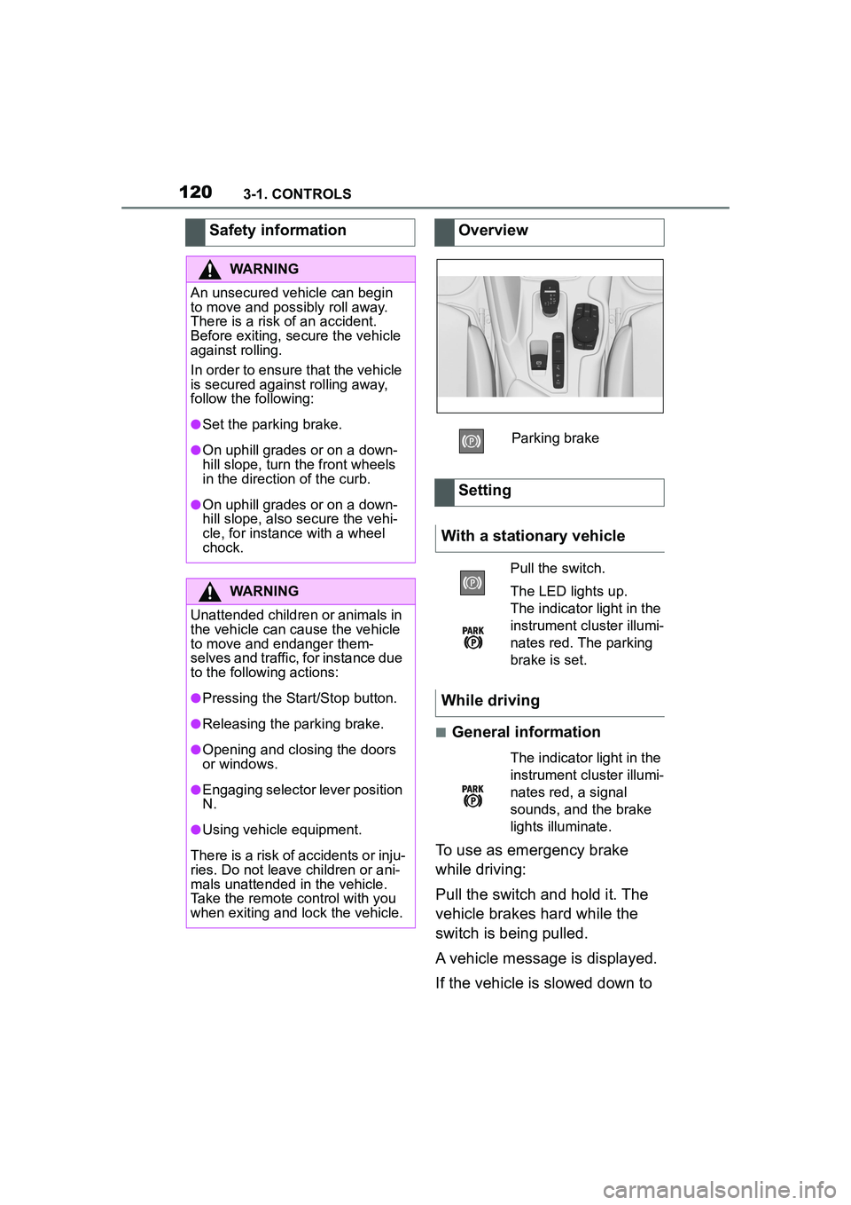
Overview
Parking brake
Setting
With a stationary vehicle
Pull the switch.
The LED lights up.
The indicator light in the
instrument cluster illumi-
nates red. The parking
brake is set.
While driving
The indicator light in the
instrument cluster illumi-
nates red, a signal
sounds, and the brake
lights illuminate.
Page 121 of 356

1213-1. CONTROLS
3
CONTROLS
a speed of approx. 2 mph/3
km/h the parking brake is set.
1Switch on drive-ready state.
2 Press the switch while
the brake is pressed or selec-
tor lever position P is set.
The LED and indicator light go out.
The parking brake is released.
The parking brake is released
automatically when you drive
away.
The LED and indicator light go
out.
In the event of a failure or mal-
function of the parking brake:
Secure the vehicle against roll-
ing away, for instance with a
wheel chock, after existing the
vehicle.
To reestablish parking brake
functionality after a power fail-
ure:
1 Switch on standby state. 2
Pull the switch while
stepping on the brake pedal
or selector lever position P is
set and then push.
This process may take a few
seconds. Any sounds associ-
ated with this are normal.
When driving and during opera-
tion of the turn signals or hazard
warning system, do not fold in
the exterior mirrors, so that the
signal lights on the exterior mir-
ror are easy to see.
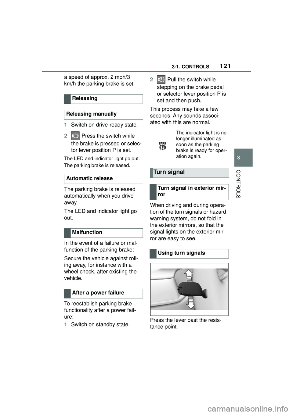
Press the lever past the resis-
tance point.
Releasing
Releasing manually
Automatic release
Malfunction
After a power failure
The indicator light is no
longer illuminated as
soon as the parking
brake is ready for oper-
ation again.
Turn signal
Turn signal in exterior mir-
ror
Using turn signals
Page 122 of 356

1223-1. CONTROLS
Lightly tap the lever up or down.
The triple turn signal duration
can be adjusted.
Via Toyota Supra Command:
1"My Vehicle"
2 "Vehicle settings"
3 "Exterior lighting"
4 "One-touch turn signal"
5 Select the desired setting.
Press the lever to the resistance
point and hold it there for as
long as you want the turn signal
to flash.
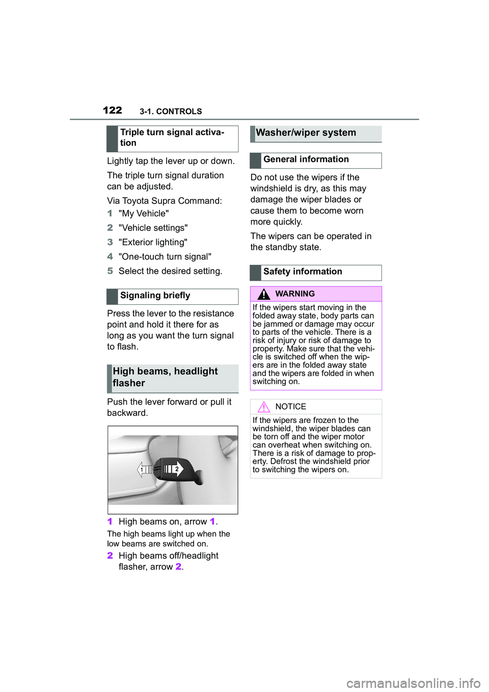
Push the lever forward or pull it
backward.
1 High beams on, arrow 1.
The high beams light up when the
low beams are switched on.
2High beams off/headlight
flasher, arrow 2. Do not use the wipers if the
windshield is dry, as this may
damage the wiper blades or
cause them to become worn
more quickly.
The wipers can be operated in
the standby state.
Triple turn signal activa-
tion
Signaling briefly
High beams, headlight
flasher
Washer/wiper system
General information
Safety information
WARNING
If the wipers start moving in the
folded away state, body parts can
be jammed or damage may occur
to parts of the vehicle. There is a
risk of injury or risk of damage to
property. Make sure that the vehi-
cle is switched off when the wip-
ers are in the folded away state
and the wipers are folded in when
switching on.
NOTICE
If the wipers are frozen to the
windshield, the wiper blades can
be torn off and the wiper motor
can overheat when switching on.
There is a risk of damage to prop-
erty. Defrost the windshield prior
to switching the wipers on.
Page 124 of 356

1243-1. CONTROLS
Press the lever up once from its
standard position, arrow 1.
Wiping is started.
The LED in the wiper lever is
illuminated.
In frosty conditions, wiper oper-
ation may not start.
Press the lever back into the
standard position.
Turn the thumbwheel to adjust
the sensitivity of the rain sensor.
Upward: high rain sensor sensi-
tivity. Downward: low rains sensor
sensitivity.
Pull the lever.
The system sprays washer fluid
on the windshield and activates
the wipers briefly.
Activating
Deactivating
Adjusting the rain sensor
sensitivity
Windshield washer system
Safety information
WARNING
The washer fluid can freeze onto
the window at low temperatures
and obstruct the view. There is a
risk of an accident. Only use the
washer systems, if the washer
fluid cannot freeze. Use washer
fluid with antifreeze, if needed.
NOTICE
When the washer fluid reservoir is
empty, the wash pump cannot
work as intended. There is a risk
of damage to property. Do not use
the washer system when the
washer fluid reservoir is empty.
Cleaning the windshield
Page 125 of 356

1253-1. CONTROLS
3
CONTROLS
The windshield washer nozzles
are automatically heated while
standby state is switched on.
In the fold-out position, the wip-
ers can be folded out from the
windshield, which is important,
for instance, when changing the
wiper blades or for folding away
under frosty conditions.1
Switch on standby state.
2 Move the wiper lever to the
lowest position and hold it
there until the wipers stop at
a nearly vertical position.
3 Fold the wipers all the way
away from the windshield.
After the wipers are folded back
down, the wiper system must be
reactivated.
1 Fold the wipers back down
onto the windshield.
2 Switch on standby state and
press and hold the wiper
lever down again.
Windshield washer nozzles
Fold-away position of the
wipers
Principle
Safety information
WARNING
If the wipers start moving in the
folded away state, body parts can
be jammed or damage may occur
to parts of the vehicle. There is a
risk of injury or risk of damage to
property. Make sure that the vehi-
cle is switched off when the wip-
ers are in the folded away state
and the wipers are folded in when
switching on.
NOTICE
If the wipers are frozen to the
windshield, the wiper blades can
be torn off and the wiper motor
can overheat when switching on.
There is a risk of damage to prop-
erty. Defrost the windshield prior
to switching the wipers on.
Folding away the wipers
Folding down the wipers