2022 TOYOTA GR SUPRA stop start
[x] Cancel search: stop startPage 178 of 356

1783-1. CONTROLS
Only objects that are detected
by the system are taken into
account.
The following situations may not
be detected, for instance:
Thus, a system reaction might
not come or might come late.
The following situations may not
be detected, for instance:
Slow moving vehicles when
you approach them at high
speed.
Vehicles that suddenly swerve in front of you, or
sharply decelerating vehicles.
Vehicles with an unusual rear
appearance.
Two-wheeled vehicles ahead
of you.
If the vehicle speed exceeds
approx. 155 mph/250 km/h, the
system is deactivated temporar-
ily. When the vehicle slows
down to below this speed, the
system is reactivated.
Additional information:
• Cameras, refer to page 40.
• Radar sensors, refer to page 41.
The system may not be fully
functional in the following situa-
tions:
In tight curves.
If the driving stability control
systems are limited or deacti-
vated, for instance VSC OFF.
Up to 10 seconds after the
start of the engine via the
Start/Stop button.
The more sensitive the warning
System limits
Safety information
WARNING
The system is designed to oper-
ate in certain conditions and cir-
cumstances. Due to conditions or
other factors, the system may not
respond. There may be a risk of
accident or risk of damage to
property. Actively intervene as
warranted. Refer to the informa-
tion in this Owner’s Manual
regarding the scope of the sys-
tem’s operation and limitations.
Detection range
Upper speed limit
System limits of the sensors
Functional limitations
Warning sensitivity
Page 182 of 356

1823-1. CONTROLS
stepping on the accelerator
pedal or by actively moving the
steering wheel.
The system’s ability to detect
objects may be limited in some
circumstances. Refer to the
information in this Owner’s Man-
ual regarding the limitations of
the system and actively inter-
vene as warranted.
The system responds to pedes-
trians and cyclists when the
speed of the vehicle is below
approx. 53 mph/85 km/h.
The system's detection potential
is limited.
Thus, a warning might not be
issued or be issued late.The following situations may not
be detected, for instance:
Partially covered pedestrians.
Pedestrians that are not
detected as such because of
the viewing angle or contour.
Pedestrians outside of the
detection range.
Pedestrians having a body
size less than 32 in/80 cm.
Additional information:
• Cameras, refer to page 40.
• Radar sensors, refer to page 41.
The system may not be fully
functional or may not be avail-
able in the following situations:
If the driving stability control
systems are deactivated, for
instance VSC OFF.
Up to 10 seconds after the
start of the engine via the
Start/Stop button.
The lane departure warning
alerts when the vehicle is about
to run off the road or exit the
lane.
System limits
Safety information
WARNING
The system is designed to oper-
ate in certain conditions and cir-
cumstances. Due to conditions or
other factors, the system may not
respond. There may be a risk of
accident or risk of damage to
property. Actively intervene as
warranted. Refer to the informa-
tion in this Owner’s Manual
regarding the scope of the sys-
tem’s operation and limitations.
Upper speed limit
Detection range
System limits of the sensors
Functional limitations
Lane departure warning
Concept
Page 187 of 356

1873-1. CONTROLS
3
CONTROLS
When lane markings are cov-
ered in snow, ice, dirt or
water.
In tight curves or on narrow
lanes.
When lane markings are cov-
ered by objects.
When driving very close to the
vehicle in front of you.
Up to 10 seconds after the
start of the engine via the
Start/Stop button.
A vehicle message may be dis-
played when the system is not
fully functional.
*: if equipped
Blind spot monitor detects vehi-
cles in the blind spot or vehicles
approaching from behind in the
adjacent lane. A warning is
issued in various gradations in
these situations. Radar sensors monitor the area
behind and next to the vehicle
when traveling faster than a
minimum speed.
The minimum speed is coun-
try-specific and is displayed in
the menu for the Toyota Supra
Safety systems.
The system indicates whether
there are vehicles in the blind
spot, arrow 1, or approaching
from behind in the adjacent
lane, arrow
2.
The light in the exterior mirror
lights up dimmed.
Before you change lanes after
setting the turn signal, the sys-
tem issues a warning in the situ-
ations described above.
The light in the exterior mirror
flashes and the steering wheel
vibrates.
Blind spot monitor*
Concept
General information
Safety information
WARNING
The system cannot serve as a
substitute for the driver’s personal
judgment in assessing visibility
and traffic situation. There is a risk
of an accident. Adjust driving style
to traffic conditions. Watch traffic
closely and actively intervene
where appropriate.
Page 193 of 356

1933-1. CONTROLS
3
CONTROLS
The system is switched on each
time drive-ready state is
switched on.
After travel has begun, the sys-
tem monitors certain aspects of
the driver's behavior, so that
decreasing alertness or fatigue
can be detected.
This procedure takes the follow-
ing criteria into account:
Personal driving style, for
instance steering behavior.
Driving conditions, for
instance length of trip.
Starting at approx. 43 mph/70
km/h, the system is active and
can also display a recommenda-
tion to take a break.
The Driver attention control is
active automatically with each
switching on of drive-ready state
and can thus display a break
recommendation.
The break recommendation can
also be switched on or off and
adjusted via Toyota Supra Com-
mand.
Via Toyota Supra Command:
1 "My Vehicle"
2 "Vehicle settings" 3
"Driver attention control"
4 Select desired setting:
"Standard": the break recom-
mendation is made with a
defined value.
"Sensitive": the break recom-
mendation is issued earlier.
"Off": no break recommenda-
tion is made.
If the driver becomes less alert
or fatigued, a message is dis-
played in the Control Display
with the recommendation to
take a break.
During the display, the following
settings can be selected:
"Do not ask again"
"Places to stop"
"Remind me later"
The break recommendation is
repeated after 20 minutes.
After a break, another recom-
mendation to take a break can-
not be displayed until after
approximately 45 minutes.
The function may be limited in
the following situations and may
be output an incorrect warning
or no warning at all.
When the clock is set incor-
rectly.
Function
Break recommendation
Settings
Display
System limits
Page 195 of 356

1953-1. CONTROLS
3
CONTROLS
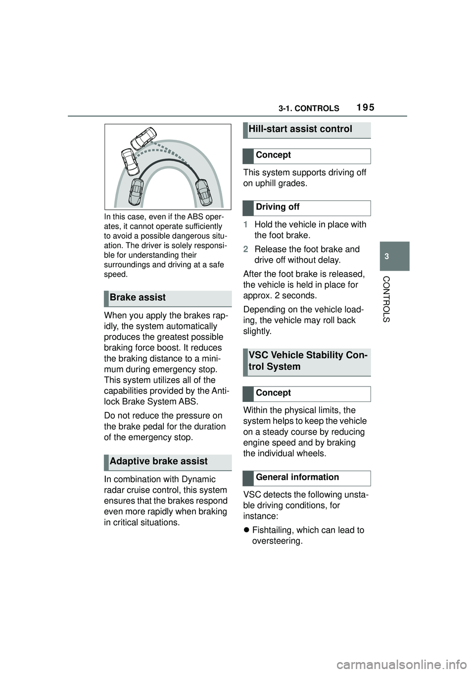
In this case, even if the ABS oper-
ates, it cannot operate sufficiently
to avoid a possible dangerous situ-
ation. The driver is solely responsi-
ble for understanding their
surroundings and driving at a safe
speed.
When you apply the brakes rap-
idly, the system automatically
produces the greatest possible
braking force boost. It reduces
the braking distance to a mini-
mum during emergency stop.
This system utilizes all of the
capabilities provided by the Anti-
lock Brake System ABS.
Do not reduce the pressure on
the brake pedal for the duration
of the emergency stop.
In combination with Dynamic
radar cruise control, this system
ensures that the brakes respond
even more rapidly when braking
in critical situations.This system supports driving off
on uphill grades.
1
Hold the vehicle in place with
the foot brake.
2 Release the foot brake and
drive off without delay.
After the foot brake is released,
the vehicle is held in place for
approx. 2 seconds.
Depending on the vehicle load-
ing, the vehicle may roll back
slightly.
Within the physical limits, the
system helps to keep the vehicle
on a steady course by reducing
engine speed and by braking
the individual wheels.
VSC detects the following unsta-
ble driving conditions, for
instance:
Fishtailing, which can lead to
oversteering.
Brake assist
Adaptive brake assist
Hill-start assist control
Concept
Driving off
VSC Vehicle Stability Con-
trol System
Concept
General information
Page 255 of 356

2554-1. DRIVING TIPS
4
DRIVING TIPS
other vehicles, etc. Increase
the distance between your
vehicle and preceding vehi-
cles and drive safely at a
lower speed than normal,
avoiding sudden accelera-
tion, braking or steering oper-
ations.
Use the rear defroster and air
conditioning system to pre-
vent the windows from fog-
ging up.
Hydroplaning is more likely to
occur when driving on ruts or
through large puddles.
On wet or slushy roads, a
wedge of water can form
between the tires and road sur-
face.
This phenomenon is referred to
as hydroplaning. It is character-
ized by a partial or complete
loss of contact between the tires
and the road surface, ultimately
undermining your ability to steer
and brake the vehicle.
When driving through water, fol-
low the following:
Deactivate Auto Start/Stop
function.
Drive through calm water only.
Drive through water only if it is
not deeper than maximum 9.8
inches/25 cm.
Drive through water no faster
than walking speed, up to 3
mph/5 km/h.
The vehicle is equipped with an
Antilock Braking System ABS as
a standard feature.
Perform an emergency stop in
situations that require such.
Steering is still responsive. You
can still avoid any obstacles with
a minimum of steering effort.
Pulsation of the brake pedal and
sounds from the hydraulic cir-
cuits indicate that the Antilock
Braking System ABS is in its
active mode.
In certain braking situations, the
Hydroplaning
Driving through water
General information
Safety information
NOTICE
When driving too quickly through
too deep water, water can enter
into the engine compartment, the
electrical system or the transmis-
sion. There is a risk of damage to
property. When driving through
water, do not exceed the maxi-
mum indicated water level and the
maximum speed for driving
through water.
Braking safely
General information
Page 259 of 356

2594-1. DRIVING TIPS
4
DRIVING TIPS
vehicle roll.
The flow of fuel is interrupted
while coasting.
Switch off the engine during lon-
ger stops, for instance at traffic
lights, railroad crossings or in
traffic congestion.
The Auto Start/Stop function of
the vehicle automatically
switches off the engine during a
stop.
If the engine is switched off and
then restarted rather than leav-
ing the engine running con-
stantly, fuel consumption and
emissions are reduced. Sav-
ings can begin within a few sec-
onds of switching off the engine.
In addition, fuel consumption is
also determined by other fac-
tors, such as driving style, road
conditions, maintenance or envi-
ronmental factors.
Functions such as seat heating
and the rear window defroster require a lot of energy and
increase fuel consumption,
especially in city and
stop-and-go traffic.
Switch off these functions if they
are not needed.
Have the vehicle maintained
regularly to achieve optimal
vehicle efficiency and service
life. Toyota recommends that
maintenance work be performed
by Toyota.
For information on the Mainte-
nance System, refer to page
301.
Switch off the engine
during longer stops
Switching off the engine
Auto Start/Stop function
Switch off any functions
that are not currently
needed
Have maintenance carried
out
Page 288 of 356

2885-1. MOBILITY
Perform a system reset again.
• Tire Pressure Monitor mal- function: have the system
checked by a manufacturer
service center or another
qualified service center or
repair shop.
• Each tire, including the spare (if provided) should be
checked monthly when cold
and inflated to the inflation
pressure recommended by
the vehicle manufacturer on
the vehicle placard or tire
inflation pressure label. (If
your vehicle has tires of a dif-
ferent size than the size indi-
cated on the vehicle placard
or tire inflation pressure label,
you should determine the
proper tire inflation pressure
for those tires.) As an added
safety feature, your vehicle
has been equipped with a tire
pressure monitoring system
(TPMS) that illuminates a low
tire pressure telltale when one
or more of your tires is signifi-
cantly under-inflated. Accord-
ingly, when the low tire
pressure telltale illuminates,
you should stop and check
your tires as soon as possi-
ble, and inflate them to the
proper pressure. Driving on a significantly under-inflated tire
causes the tire to overheat
and can lead to tire failure.
Under-inflation also reduces
fuel efficiency and tire tread
life, and may affect the vehi-
cle's handling and stopping
ability. Please note that the
TPMS is not a substitute for
proper tire maintenance, and
it is the driver's responsibility
to maintain correct tire pres-
sure, even if under-inflation
has not reached the level to
trigger illumination of the
TPMS low tire pressure tell-
tale. Your vehicle has also
been equipped with a TPMS
malfunction indicator to indi-
cate when the system is not
operating properly. The TPMS
malfunction indicator is com-
bined with the low tire pres-
sure telltale. When the system
detects a malfunction, the tell-
tale will flash for approxi-
mately one minute and then
remain continuously illumi-
nated. This sequence will
continue upon subsequent
vehicle start-ups as long as
the malfunction exists. When
the malfunction indicator is
illuminated, the system may
not be able to detect or signal
low tire pressure as intended.
TPMS malfunctions may
occur for a variety of reasons,
including the installation of
replacement or alternate tires
Declaration according to
NHTSA/FMVSS 138 Tire
Pressure Monitoring System