Page 219 of 356

2193-1. CONTROLS
3
CONTROLS
The system is controlled by the
following sensors:
• Rearview camera.
Additional information:
Sensors of the vehicle, refer to
page 40.
The system is switched on auto-
matically if selector lever posi-
tion R is engaged when the
engine is running.
The system switches off when a
certain driving distance or speed is exceeded.
Switch the system back on, if
needed.
On: the LED lights up.
Off: the LED goes out.
The parking assistance func-
tions are shown on the Control
Display.
If the rearview camera view is
not displayed, change the view
via Toyota Supra Command:
1 If necessary, tilt the controller
to the side.
2 "Rear view camera"
The rearview camera image is
displayed.
The rearview camera is
switched on.
Keep the recording range of
the camera clear. Protruding
cargo or roof rack systems
can limit the detection range
of the camera.
Overview
Depending on the vehicle
equipment: button in the
vehicle
Park assistance button
Sensors
Switching on/off
Switching on automatically
Automatic deactivation
during forward travel
Depending on the vehicle
equipment: switching on/off
manually
Press the park assistance
button.
Switching the view via Toy-
ota Supra Command
Functional requirements
Page 220 of 356

2203-1. CONTROLS
More than one assistance func-
tion can be active at the same
time.
The assistance functions can be
manually activated.
1Move the Controller to the
right, if needed.
2 With corresponding equip-
ment:
3 With corresponding equip-
ment: "Camera image"
"Parking aid lines".
Pathway lines and turning radius
lines are displayed, refer to page
220.
"Obstacle marking".
Depending on the vehicle equip-
ment, the obstacles detected by
Parking Sensors are displayed,
refer to page
221, by markings.
■Pathway lines Pathway lines help you to esti-
mate the space required when
parking and maneuvering on
level roads.
Pathway lines depend on the
steering angle and are continu-
ously adjusted to the steering
wheel movements.
■Turning radius lines
Turning radius lines can only be
superimposed on the camera
image together with pathway
lines.
Turning radius lines show the
course of the smallest possible
turning radius on a level road.
Only one turning radius line is
displayed after the steering
wheel is turned past a certain
angle.
■Parking using pathway and
turning radius lines
1 Position the vehicle so that
the red turning radius line
leads to within the limits of
the parking space.
2 Turn the steering wheel to
the point where the green
pathway line covers the cor-
Display on the Control Dis-
play
General information
Parking aid lines
Page 221 of 356

2213-1. CONTROLS
3
CONTROLS
responding turning radius
line.
Depending on the vehicle equip-
ment, obstacles behind the vehi-
cle are detected by the Parking
Sensors.
Obstacle markings can be faded
into the image of the rearview
camera.
The colored thresholds of the
obstacle markings match the
markings of the Parking Sen-
sors.
With the rearview camera
switched on:
1 Move the Controller to the
left, if needed.
2 "Camera image"
3
"Brightness"
"Contrast" 4
Set the desired value.
Additional information:
• Cameras, refer to page 40.
If the camera is deactivated, for
instance if the trunk lid is open,
the camera image is displayed
hatched in gray.
Very low obstacles as well as
high, protruding objects such as
ledges may not be detected by
the system.
Depending on the vehicle equip-
ment, some assistance func-
tions also consider data from the
Parking Sensors.
Follow the notes in the Parking
Sensors chapter.
The objects displayed on the
Control Display may be closer
than they appear. Do not esti-
mate the distance from the
objects on the display.
*: if equipped
Obstacle marking
Setting brightness and
contrast via Toyota Supra
Command
System limits
System limits of the sensors
Deactivated camera
Detection of objects
RCTA (Rear cross traffic
alert) function*
Page 223 of 356

2233-1. CONTROLS
3
CONTROLS
1"My vehicle"
2 "Vehicle settings"
3 "Parking"
4 "Cross traffic alert"
5 "Cross traffic alert"
If the system was activated on
the Control Display, it is auto-
matically switched on as soon
as Parking Sensors or Pan-
orama View is active and a gear
is engaged.
If reverse gear is engaged, the
rear system is switched on.
The system is automatically
switched off in the following situ-
ations:
When the speed exceeds
walking speed.
When a certain driving dis-
tance is exceeded.
With an active parking opera-
tion of the parking assistant.
The respective display is called
up on the Control Display. A sig-
nal tone may sound and the light
in the exterior mirror may flash. The light in the exterior mirror
flashes if vehicles are detected
by the rear sensors and your
own vehicle is moving back-
wards.
In the Parking Sensors view, the
respective boundary area
flashes red, if vehicles are
detected by the sensors.
In addition to the optical indica-
tor, a warning signal sounds if
your own vehicle moves into the
respective direction.
Switching on automatically
Switching off automatically
WARNING
General informationLight in the exterior mirror
Display in the Parking Sen-
sors view
Acoustic warning
Page 230 of 356

2303-1. CONTROLS
recirculated.
To prevent window fogging,
recirculated-air mode switches
off automatically after a certain
amount of time, depending on
the environmental conditions.
With constant recirculated-air
mode, the air quality in the car's
interior deteriorates and the fog-
ging of the windows increases.
If there is window condensation,
switch off recirculated-air mode
or defog the windows, refer to
page 230.
The air flow for climate control
can be adjusted manually.
To manually adjust air flow
switch off AUTO program first.
The selected air flow is shown
on the climate control display.
The air flow may be reduced
automatically to save battery
power.The air distribution for climate
control can be adjusted manu-
ally.
Windows, upper body region,
and floor area.
Upper body region and floor
area.
Floor area.
Windows and floor area.
Windows.
Windows and upper body.
Upper body region.
The selected air distribution is
shown on the climate control
display.
If there is window condensation,
defog the windows, refer to
page P.230.
Ice and condensation are
Controlling the air flow
manually
Concept
General information
Operation
Press the left or right
side of the button:
decrease or increase air
flow.
Controlling the air distri-
bution manually
Concept
Operation
Press the button repeat-
edly to select a program:
Defrost windshield and
remove condensation
Concept
Page 233 of 356

2333-1. CONTROLS
3
CONTROLS
■Switching on
Press any button except:
Rear window defroster.
Lower air flow button side.
Seat heating.
Menu.
■Switching off
The system switches off after
leaving and locking the vehicle.
Press and hold the bot-
tom button.
1 "My Vehicle"
2 "Vehicle settings"
3 "Climate functions"
4 "Comfort ventilation"
5 "Activate now" Different departure times can be
adjusted to ensure a comfort-
able interior temperature in the
vehicle at the time of departure.
One-time departure time: the
time can be set.
The system is switched on once.
Departure time with week-
day: time and day of the week
can be set.
On the desired weekdays, the sys-
tem will be switched on promptly
before the set departure time.
The departure time is prese-
lected in two steps:
Set departure times.
Activate departure times.
A minimum of 10 minutes
should pass between set-
ting/activating the departure
time and the planned departure
time to allow a sufficient period
of time for the climate control.
■Via Toyota Supra Command
1 "My Vehicle"
2 "Vehicle settings"
3 "Climate functions"
4 "Comfort ventilation"
5 Select the desired departure
time.
Via Toyota Supra Command
Display
SymbolDescription
Symbol on the auto-
matic air conditioning
indicates the system is
switched on.
REST is displayed on
the automatic air condi-
tioning. The residual
engine heat is used.
Departure time
Concept
Setting the departure time
Page 234 of 356

2343-1. CONTROLS
6Set the departure time.
7 Select day of the week, if
needed.
■Functional requirement
If a departure time is to influ-
ence the switching on of
parked-car ventilation, the
respective departure time must
be activated first.
■Via Toyota Supra Command
1 "My Vehicle"
2 "Vehicle settings"
3 "Climate functions"
4 "Comfort ventilation"
5 "For departure time"
6 Activate the desired depar-
ture time.
The symbol on the automatic
air conditioning signals an acti-
vated departure time. This chapter describes all stan-
dard, country-specific and
optional features offered with
the series. It also describes fea-
tures and functions that are not
necessarily available in your
vehicle, e.g., due to the selected
options or country versions. This
also applies to safety-related
functions and systems. When
using these functions and sys-
tems, the applicable laws and
regulations must be observed.
The integrated Universal
Remote Control in the interior
mirror can operate up to 3 func-
tions of remote-controlled sys-
tems such as garage door
drives, barriers, or lighting sys-
tems.
The Integrated Universal
Remote Control replaces up to 3
different hand-held transmitters.
To operate the remote control,
the buttons on the interior mirror
must be programmed with the
Activating the departure time
Display
Interior equipment
Vehicle features and
options
Integrated Universal
Remote Control
Concept
General information
Page 240 of 356

2403-1. CONTROLS
devices.
Charging current:
max. 1.5 A (vehicles without wire-
less charger)
max. 2.1 A (vehicles with wireless
charger)
For data transfer.
The wireless charging tray
enables the following functions
to be performed without cables:
Charging the rechargeable
battery of a mobile phone with
Qi capability and of other
mobile devices, which support
the Qi standard.
Connect the mobile phone to
the external antenna.
Depending on the country, this pro-
vides for better network reception
and a consistent reproduction qual-
ity.
When inserting the mobile
phone, make sure there are no
objects between it and the wire-
less charging tray.
During charging, the surface of
the tray and the mobile phone
may become warm. Higher tem-
peratures may lead to a reduc-
tion in the charge current through the mobile phone, and
in isolated cases the charging
process is paused temporarily.
Follow the relevant instructions
in the mobile phone owner's
manual.
If the vehicle is equipped
with a charge indicator, the Con-
trol Display shows whether a
mobile phone with Qi capability
is being charged.
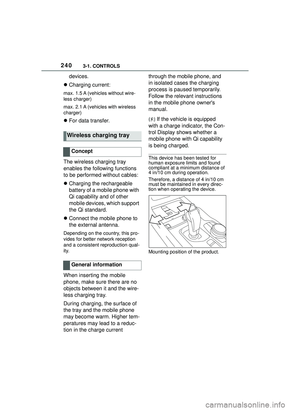
This device has been tested for
human exposure limits and found
compliant at a minimum distance of
4 in/10 cm during operation.
Therefore, a distance of 4 in/10 cm
must be maintained in every direc-
tion when operating the device.
Mounting position of the product.
Wireless charging tray
Concept
General information