2022 TOYOTA COROLLA ECU
[x] Cancel search: ECUPage 190 of 678
1884-4. Refueling
4-4.Refueling
Turn the engine switch off and
ensure that all the doors and
windows are closed.
Confirm the type of fuel.
■Fuel types
P.537
■Fuel tank opening for unleaded
gasoline
To help prevent incorrect fueling, your vehicle has a fuel tank opening that only
accommodates the special nozzle on
unleaded fuel pumps.
Opening the fuel tank
cap
Perform the following steps to
open the fuel tank cap:
Before refueling the vehicle
WA R N I N G
■When refueling the vehicle
Observe the following precautions
while refueling the vehicle. Failure to
do so may result in death or serious injury.
●After exiting the vehicle and before opening the fuel door, touch an
unpainted metal surface to dis-
charge any static electricity. It is important to discharge static elec-
tricity before refueling because
sparks resulting from static electric- ity can cause fuel vapors to ignite
while refueling.
●Always hold the grips on the fuel tank cap and turn it slowly to
remove it.
A whooshing sound may be heard when the fuel tank cap is loosened.
Wait until the sound cannot be
heard before fully removing the cap. In hot weather, pressurized
fuel may spray out the filler neck
and cause injury.
●Do not allow anyone that has not
discharged static electricity from their body to come close to an open
fuel tank.
●Do not inhale vaporized fuel.
Fuel contains substances that are
harmful if inhaled.
●Do not smoke while refueling the
vehicle. Doing so may cause the fuel to
ignite and cause a fire.
●Do not return to the vehicle or touch
any person or object that is stati-
cally charged. This may cause static electricity to
build up, resulting in a possible igni-
tion hazard.
■When refueling
Observe the following precautions to prevent fuel overflowing from the fuel
tank:
●Securely insert the fuel nozzle into
the fuel filler neck.
●Stop filling the tank after the fuel
nozzle automatically clicks off.
●Do not top off the fuel tank.
Page 264 of 678

2624-5. Using the driving support systems
vehicle cannot be detected.
*2: The greater the difference in speed between your vehicle and the detected vehi-
cle is, the farther away the vehicle will be detected, causing the outside rear view
mirror indicator to illuminate or flash.
■The Blind Spot Monitor is opera-
tional when
The Blind Spot Monitor is operational
when all of the following conditions are
met:
●The Blind Spot Monitor is on.
●The shift lever is in a position other
than R.
●The vehicle speed is greater than
approximately 16 km/h (10 mph).
■The Blind Spot Monitor will detect a
vehicle when
The Blind Spot Monitor will detect a
vehicle present in the detection area in
the following situations:
●A vehicle in an adjacent lane over-
takes your vehicle.
●You overtake a vehicle in adjacent
lane slowly.
●Another vehicle enters the detection
area when it changes lanes.
■Conditions under which the system will not detect a vehicle
The Blind Spot Monitor is not designed
to detect the following types of vehicles
and/or objects:
●Small motorcycles, bicycles, pedestri-
ans, etc.*
●Vehicles traveling in the opposite
direction
●Guardrails, walls, signs, parked vehi-
cles and similar stationary objects*
●Following vehicles that are in the
same lane*
●Vehicles traveling 2 lanes away from
your vehicle*
●Vehicles which are being overtaken
rapidly by your vehicle*
*: Depending on the conditions, detec-
tion of a vehicle and/or object may
occur.
■Conditions under which the system may not function correctly
●The Blind Spot Monitor may not detect vehicles correctly in the following situ-
ations:
• When the sensor is misaligned due to a strong impact to the sensor or its
surrounding area
• When mud, snow, ice, a sticker, etc. is covering the sensor or surrounding
area on the rear bumper
• When driving on a road surface that is wet with standing water during bad
weather, such as heavy rain, snow, or
fog • When multiple vehicles are approach-
ing with only a small gap between
each vehicle • When the distance between your vehi-
cle and a following vehicle is short
• When there is a significant difference in speed between your vehicle and
the vehicle that enters the detection
area • When the difference in speed
between your vehicle and another
vehicle is changing • When a vehicle enters a detection
area traveling at about the same
speed as your vehicle • As your vehicle starts from a stop, a
vehicle remains in the detection area
• When driving up and down consecu-
tive steep inclines, such as hills, dips in the road, etc.
• When driving on roads with sharp
bends, consecutive curves, or uneven surfaces
• When vehicle lanes are wide, or when
driving on the edge of a lane, and the vehicle in an adjacent lane is far away
from your vehicle
• When towing a trailer
Page 265 of 678

263
4
4-5. Using the driving support systems
Driving
• When an accessory (such as a bicycle
carrier) is installed to the rear of the vehicle
• When there is a significant difference
in height between your vehicle and the vehicle that enters the detection
area
• Immediately after the Blind Spot Moni- tor is turned on
●Instances of the Blind Spot Monitor unnecessarily detecting a vehicle
and/or object may increase in the fol-
lowing situations: • When the sensor is misaligned due to
a strong impact to the sensor or its
surrounding area • When the distance between your vehi-
cle and a guardrail, wall, etc. that
enters the detection area is short • When driving up and down consecu-
tive steep inclines, such as hills, dips
in the road, etc. • When vehicle lanes are narrow, or
when driving on the edge of a lane,
and a vehicle traveling in a lane other than the adjacent lanes enters the
detection area
• When driving on roads with sharp bends, consecutive curves, or uneven
surfaces
• When the tires are slipping or spinning • When the distance between your vehi-
cle and a following vehicle is short
• When an accessory (such as a bicycle carrier) is installed to the rear of the
vehicle
*: If equipped
■Types of sensors
Front corner sensors
Front center sensors
Rear corner sensors
Rear center sensors
Front side sensors (if equipped)
Rear side sensors (if equipped)
■Display
When the sensors detect an object,
such as a wall, a graphic is shown
Toyota parking
assist-sensor*
The distance from your vehicle
to objects, such as a wall,
when parallel parking or
maneuvering into a garage is
measured by the sensors and
communicated via the
multi-information display,
head-up display (if equipped)
and a buzzer. Always check the
surrounding area when using
this system.
System components
Page 356 of 678
3545-6. Using Bluetooth® devices
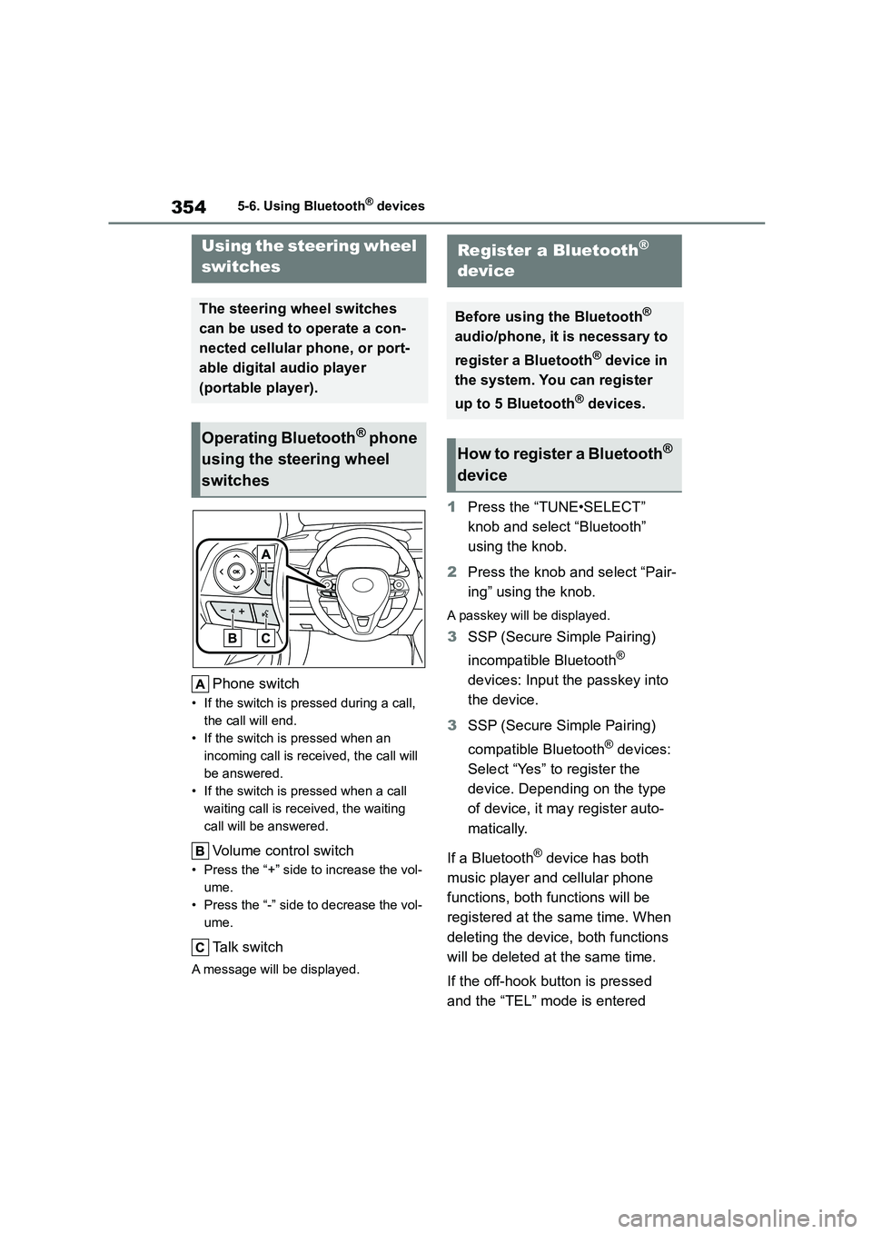
Phone switch
• If the switch is pressed during a call,
the call will end.
• If the switch is pressed when an
incoming call is received, the call will
be answered.
• If the switch is pressed when a call
waiting call is received, the waiting
call will be answered.
Volume control switch
• Press the “+” side to increase the vol-
ume.
• Press the “-” side to decrease the vol-
ume.
Talk switch
A message will be displayed.
1 Press the “TUNE•SELECT”
knob and select “Bluetooth”
using the knob.
2 Press the knob and select “Pair-
ing” using the knob.
A passkey will be displayed.
3 SSP (Secure Simple Pairing)
incompatible Bluetooth®
devices: Input the passkey into
the device.
3 SSP (Secure Simple Pairing)
compatible Bluetooth® devices:
Select “Yes” to register the
device. Depending on the type
of device, it may register auto-
matically.
If a Bluetooth® device has both
music player and cellular phone
functions, both functions will be
registered at the same time. When
deleting the device, both functions
will be deleted at the same time.
If the off-hook button is pressed
and the “TEL” mode is entered
Using the steering wheel
switches
The steering wheel switches
can be used to operate a con-
nected cellular phone, or port-
able digital audio player
(portable player).
Operating Bluetooth® phone
using the steering wheel
switches
Register a Bluetooth®
device
Before using the Bluetooth®
audio/phone, it is necessary to
register a Bluetooth® device in
the system. You can register
up to 5 Bluetooth® devices.
How to register a Bluetooth®
device
Page 422 of 678
4207-3. Do-it-yourself maintenance
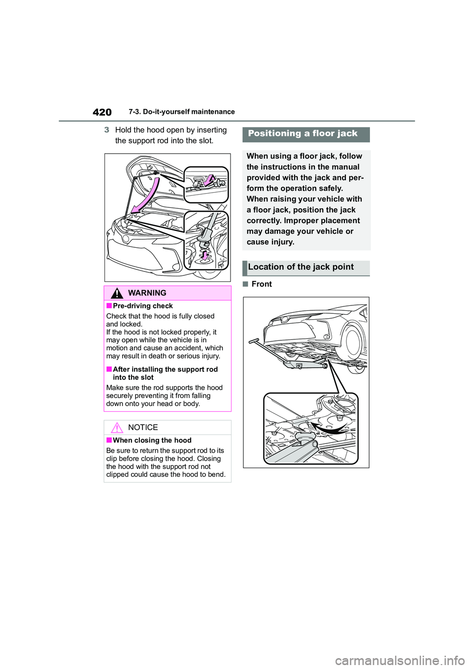
3Hold the hood open by inserting
the support rod into the slot.
■Front
WA R N I N G
■Pre-driving check
Check that the hood is fully closed
and locked.
If the hood is not locked properly, it
may open while the vehicle is in motion and cause an accident, which
may result in death or serious injury.
■After installing the support rod
into the slot
Make sure the rod supports the hood securely preventing it from falling
down onto your head or body.
NOTICE
■When closing the hood
Be sure to return the support rod to its
clip before closing the hood. Closing
the hood with the support rod not clipped could cause the hood to bend.
Positioning a floor jack
When using a floor jack, follow
the instructions in the manual
provided with the jack and per-
form the operation safely.
When raising your vehicle with
a floor jack, position the jack
correctly. Improper placement
may damage your vehicle or
cause injury.
Location of the jack point
Page 452 of 678
4507-3. Do-it-yourself maintenance
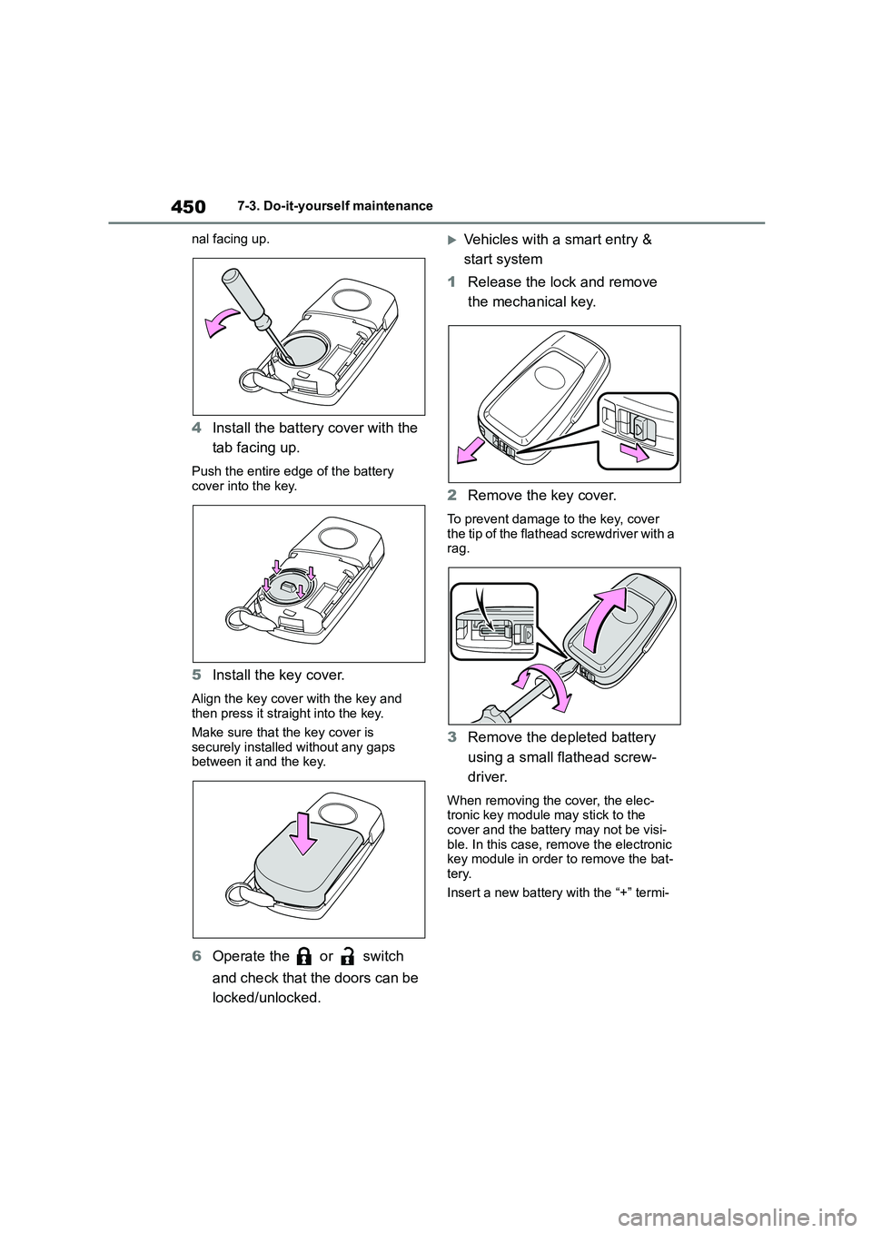
nal facing up.
4 Install the battery cover with the
tab facing up.
Push the entire edge of the battery
cover into the key.
5 Install the key cover.
Align the key cover with the key and
then press it straight into the key.
Make sure that the key cover is securely installed without any gaps
between it and the key.
6 Operate the or switch
and check that the doors can be
locked/unlocked.
Vehicles with a smart entry &
start system
1 Release the lock and remove
the mechanical key.
2 Remove the key cover.
To prevent damage to the key, cover
the tip of the flathead screwdriver with a rag.
3 Remove the depleted battery
using a small flathead screw-
driver.
When removing the cover, the elec- tronic key module may stick to the
cover and the battery may not be visi-
ble. In this case, remove the electronic key module in order to remove the bat-
tery.
Insert a new battery with the “+” termi-
Page 456 of 678
4547-3. Do-it-yourself maintenance
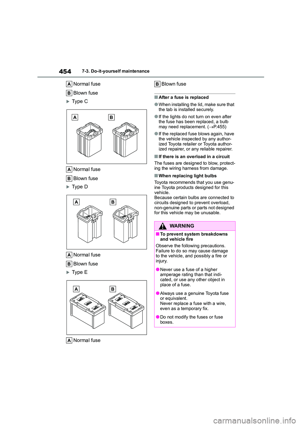
Normal fuse
Blown fuse
Type C
Normal fuse
Blown fuse
Type D
Normal fuse
Blown fuse
Type E
Normal fuse
Blown fuse
■After a fuse is replaced
●When installing the lid, make sure that
the tab is installed securely.
●If the lights do not turn on even after
the fuse has been replaced, a bulb
may need replacement. ( P.455)
●If the replaced fuse blows again, have
the vehicle inspected by any author- ized Toyota retailer or Toyota author-
ized repairer, or any reliable repairer.
■If there is an overload in a circuit
The fuses are designed to blow, protect- ing the wiring harness from damage.
■When replacing light bulbs
Toyota recommends that you use genu-
ine Toyota products designed for this vehicle.
Because certain bulbs are connected to
circuits designed to prevent overload, non-genuine parts or parts not designed
for this vehicle may be unusable.
WA R N I N G
■To prevent system breakdowns
and vehicle fire
Observe the following precautions.
Failure to do so may cause damage
to the vehicle, and possibly a fire or injury.
●Never use a fuse of a higher amperage rating than that indi-
cated, or use any other object in
place of a fuse.
●Always use a genuine Toyota fuse
or equivalent. Never replace a fuse with a wire,
even as a temporary fix.
●Do not modify the fuses or fuse
boxes.
Page 459 of 678
457
7
7-3. Do-it-yourself maintenance
Maintenance and care
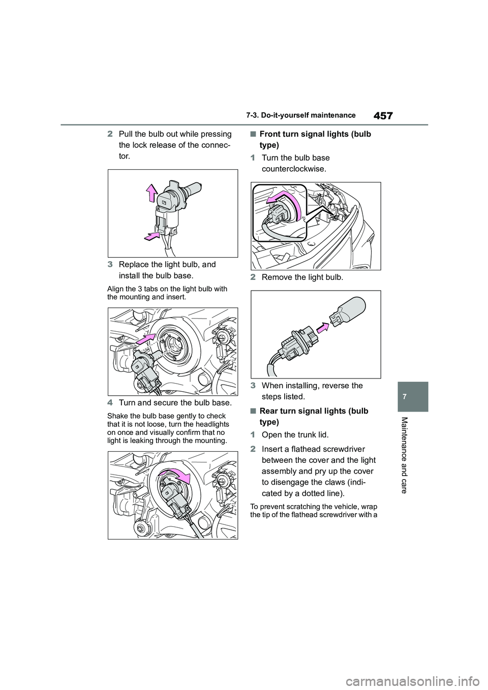
2 Pull the bulb out while pressing
the lock release of the connec-
tor.
3 Replace the light bulb, and
install the bulb base.
Align the 3 tabs on the light bulb with the mounting and insert.
4 Turn and secure the bulb base.
Shake the bulb base gently to check that it is not loose, turn the headlights
on once and visually confirm that no
light is leaking through the mounting.
■Front turn signal lights (bulb
type)
1 Turn the bulb base
counterclockwise.
2 Remove the light bulb.
3 When installing, reverse the
steps listed.
■Rear turn signal lights (bulb
type)
1 Open the trunk lid.
2 Insert a flathead screwdriver
between the cover and the light
assembly and pry up the cover
to disengage the claws (indi-
cated by a dotted line).
To prevent scratching the vehicle, wrap
the tip of the flathead screwdriver with a