Page 65 of 678

63
1
1-2. Child safety
For safety and security
If the head restraint interferes with the
child restraint system or top strap instal- lation and the head restraint can be
removed, remove th e head restraint.
( P.128)
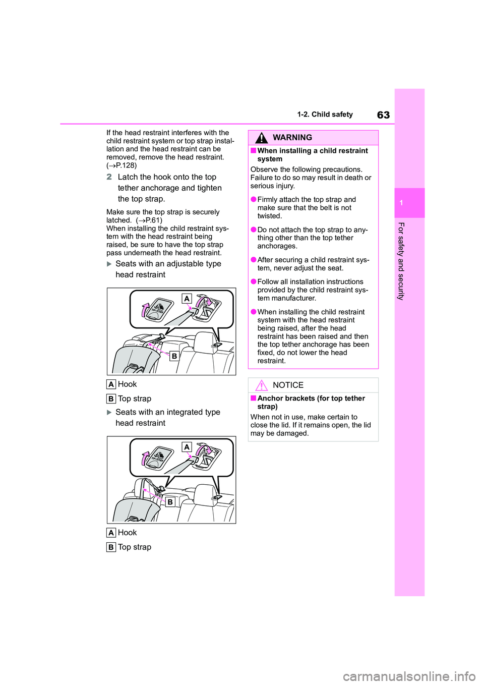
2Latch the hook onto the top
tether anchorage and tighten
the top strap.
Make sure the top strap is securely
latched. ( P. 6 1 ) When installing the child restraint sys-
tem with the head restraint being
raised, be sure to have the top strap pass underneath the head restraint.
Seats with an adjustable type
head restraint
Hook
To p s t r a p
Seats with an integrated type
head restraint
Hook
To p s t r a p
WA R N I N G
■When installing a child restraint
system
Observe the following precautions. Failure to do so may result in death or
serious injury.
●Firmly attach the top strap and
make sure that the belt is not
twisted.
●Do not attach the top strap to any-
thing other than the top tether
anchorages.
●After securing a ch ild restraint sys-
tem, never adjust the seat.
●Follow all installation instructions
provided by the child restraint sys- tem manufacturer.
●When installing the child restraint system with the head restraint
being raised, after the head
restraint has been raised and then the top tether anchorage has been
fixed, do not lower the head
restraint.
NOTICE
■Anchor brackets (for top tether
strap)
When not in use, make certain to close the lid. If it remains open, the lid
may be damaged.
Page 67 of 678

65
1
1-3. Emergency assistance
For safety and security
tance required.
Make sure to open the cover before
pressing the “SOS” button.
If you accidentally press the “SOS” but-
ton, tell the operator that you are not
experiencing an emergency.
*: In some cases, the call cannot be
made. ( P. 6 5 )
When the engine switch is turned to
ON, the red indicato r light will illumi-
nate for 10 seconds. Then, the
green indicator light will illuminate
for 2 seconds and remain illumi-
nated if the system is functioning
properly. The indicator lights indi-
cate the following:
If the green indicator light illumi-
nates and stays on, the system is
enabled.
If the green indicator light
flashes, an automatic or manual
Emergency Call is being made.
If the red indicator light illumi-
nates and a buzzer sounds 5
times (on some models) at any
time other than immediately after
the engine switch is turned to
ON, the system may be malfunc-
tioning or the backup battery
may be depleted.
If the red indicator light blinks for
approximately 30 seconds during
an Emergency Call, the call has
been disconnected or the cellular
network signal is weak.
■Free/Open Source Software Infor-
mation
This product contains Free/Open
Source Software (FOSS).
The license information and/or the source code of such FOSS can be found
at the following URL.
http://www.opensourceautomotive.com/dcm/toyota/
http://www.opensourceautomotive.com/
dcm/toyota/19MC/Indicator lights
WA R N I N G
■When the Emergency Call may not be made
●It may not be possible to make
Emergency Calls in any of the fol- lowing situations. In such cases,
report to emergency services pro-
vider (112 system etc.) by other means such as nearby public
phones.
• Even when the vehicle is in the cel- lular phone service area, it may be
difficult to connect to the eCall con-
trol center if the reception is poor or the line is busy. In such cases, even
though the system attempts to con-
nect to the eCall control center, you may not be able to connect to the
eCall control center to make Emer-
gency Calls and contact emergency services.
• When the vehicle is out of the cellu-
lar phone service area, the Emer- gency Calls cannot be made.
Page 69 of 678
67
1
1-3. Emergency assistance
For safety and security
■Data processing flow
Server
Storage
Processing
DCM
1 Customer activates service on Toyota Customer portal & accepts terms
of services according to GDPR.
NOTICE
■If the “SOS” button panel,
speaker or microphone malfunc-
tions during an Emergency Call or manual maintenance check
It may not be possible to make Emer-
gency Calls, confirm the system sta- tus, or communicate with the eCall
control center operator. If any of the
above equipment is damaged, please
consult any authorized Toyota retailer or Toyota authorized repairer, or any
reliable repairer.
System overview of added service
Page 71 of 678

69
1
1-3. Emergency assistance
For safety and security
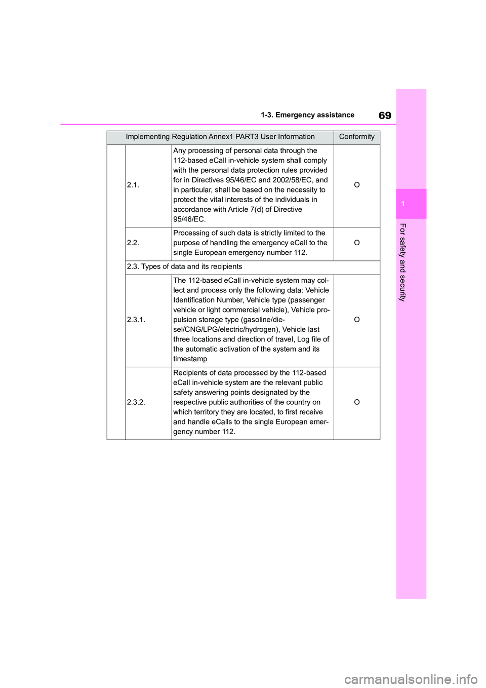
2.1.
Any processing of personal data through the
112-based eCall in-vehicle system shall comply
with the personal data protection rules provided
for in Directives 95/46/EC and 2002/58/EC, and
in particular, shall be based on the necessity to
protect the vital interests of the individuals in
accordance with Article 7(d) of Directive
95/46/EC.
O
2.2.
Processing of such data is strictly limited to the
purpose of handling the emergency eCall to the
single European emergency number 112.
O
2.3. Types of data and its recipients
2.3.1.
The 112-based eCall in-v ehicle system may col-
lect and process only the following data: Vehicle
Identification Number, Vehicle type (passenger
vehicle or light commercia l vehicle), Vehicle pro-
pulsion storage type (gasoline/die-
sel/CNG/LPG/electric/hydr ogen), Vehicle last
three locations and direction of travel, Log file of
the automatic activation of the system and its
timestamp
O
2.3.2.
Recipients of data processed by the 112-based
eCall in-vehicle system are the relevant public
safety answering points designated by the
respective public authorities of the country on
which territory they are located, to first receive
and handle eCalls to the single European emer-
gency number 112.
O
Implementing Regulation Annex1 PART3 User InformationConformity
Page 73 of 678

71
1
1-3. Emergency assistance
For safety and security
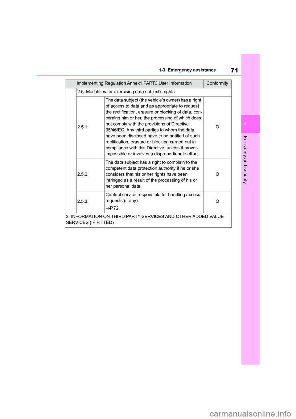
2.5. Modalities for exercising data subject’s rights
2.5.1.
The data subject (the vehicle’s owner) has a right
of access to data and as appropriate to request
the rectification, erasure or blocking of data, con-
cerning him or her, the processing of which does
not comply with the provisions of Directive
95/46/EC. Any third parties to whom the data
have been disclosed have to be notified of such
rectification, erasure or blocking carried out in
compliance with this Directive, unless it proves
impossible or involves a disproportionate effort.
O
2.5.2.
The data subject has a right to complain to the
competent data protection authority if he or she
considers that his or her rights have been
infringed as a result of the processing of his or
her personal data.
O
2.5.3.
Contact service responsible for handling access
requests (if any):
P. 7 2
O
3. INFORMATION ON THIRD PARTY SERVICES AND OTHER ADDED VALUE
SERVICES (IF FITTED)
Implementing Regulation Annex1 PART3 User InformationConformity
Page 75 of 678
Page 76 of 678

741-4. Theft deterrent system
1-4.Theft deterrent system
Vehicles without a smart entry &
start system
The indicator light flashes after the
key has been removed from the
engine switch to indicate that the
system is operating.
The indicator light stops flashing
after the registered key has been
inserted into the engine switch to
indicate that the system has been
canceled.
Vehicles with a smart entry &
start system
The indicator light flashes after the
engine switch has been turned off
to indicate that the system is oper-
ating.
The indicator light stops flashing
after the engine switch has been
turned to ACC or ON to indicate
that the system has been canceled.
■System maintenance
The vehicle has a maintenance-free
type engine immobilizer system.
■Conditions that may cause the sys-
tem to malfunction
●If the grip portion of the key is in con-
tact with a metallic object
●If the key is in close proximity to or
touching a key to the security system (key with a built-in transponder chip)
of another vehicle
Engine immobilizer sys-
tem
The vehicle’s keys have
built-in transponder chips that
prevent the engine from start-
ing if a key has not been previ-
ously registered in the
vehicle’s on-board computer.
Never leave the keys inside the
vehicle when you leave the
vehicle.
This system is designed to
help prevent vehicle theft but
does not guarantee absolute
security against all vehicle
thefts.
Operating the system
NOTICE
■To ensure the system operates
correctly
Do not modify or remove the system.
If modified or removed, the proper
operation of the system cannot be guaranteed.
Page 77 of 678
75
1
1-4. Theft deterrent system
For safety and security
*: If equipped
■Setting
Turn the engine switch off, have all
the passengers exit the vehicle and
ensure that all the doors are closed.
Using the entry function (if
equipped): Touch the sensor area
on the outside door handle twice
within 5 seconds.
Using the wireless remote control:
Press twice within 5 seconds.
■Canceling
Using the entry function (if
equipped): Hold the outside door
handle.
Using the wireless remote control:
Press .
Double locking system*
Unauthorized access to the
vehicle is prevented by
disabling the door unlocking
function from both the interior
and exterior of the vehicle.
Vehicles employing this sys-
tem have labels on the window
glass of both front doors.
Setting/canceling the double
locking system
WA R N I N G
■Double locking system precau-
tion
Never activate the double locking sys-
tem when there are people in the vehicle because all the doors cannot
be opened from inside the vehicle.