Page 161 of 276
159
Practical information
7POWERCHARGE FAULT SymbolDescription
(green)
Connected only to the infrastructure or to the
infrastructure and to the Electric Vehicle (EV) but
no charging in progress.
(green)
(green)
Connected to the power supply and to the Electric
Vehicle (EV).
The EV is on charge or in a temperature pre-
conditioning sequence.
(green)
(green)
Connected to the power supply and to the Electric
Vehicle (EV).
The EV is waiting for charging or the charging of
the EV is completed.
(red)
Control unit malfunction. No charging allowed.
If an error indicator reappears after a manual reset,
the control unit must be checked by a CITROËN
dealer before the next charge.
(green)
(green)
(red)
The control unit is in diagnostic mode.
Manual reset procedure
The control unit can be reset by simultaneously disconnecting the chargi\
ng connector and the wall socket.
Then, reconnect the wall socket first. For more information, refer to the handbook.
Page 162 of 276
 160
Practical information
or electrocution in the event of contact with or
immersion in water!
Charging procedure
Connection
► Before charging, check that the gear selector
is in mode P and the i")
160
Practical information
or electrocution in the event of contact with or
immersion in water!
Charging procedure
Connection
► Before charging, check that the gear selector
is in mode P and the ignition is off, otherwise
charging is impossible.
► Open the charging flap by pressing the top
right push-button, and check that there are
no foreign bodies on the vehicle's charging
connector.
The light guides in the flap come on white.
Domestic charging (mode 2)
► First, connect the charging cable from the
control unit to the domestic socket.
Charging the traction
battery (Rechargeable
hybrid)
For a full charge, follow the charging procedure
without interrupting it, until it stops automatically.
Charging may be performed either immediately
(by default) or deferred.
Deferred charging is set via the touch
screen or the MyCitroën application.
When the vehicle is connected, the following
information is displayed on the instrument panel:
–
Status of the battery (%).
–
Remaining range (miles or km).
–
Estimated charging time (calculation may take
a few seconds).
–
Charging speed (kW/h).
After the instrument panel has been put into
standby mode, this information can be displayed
again by unlocking the vehicle or opening a door
.
It is also possible to monitor the charging
progress using the MyCitroën
application.
For more information on Remote functions,
refer to the corresponding section.
Vehicle immobilised for up to 4 weeks
Park the vehicle in a covered area.
Connect the charging cable to supply power
to the traction battery.
Vehicle immobilised for 1 to 12
months
Discharge the traction battery down to 2 or
3 bars on the charge level indicator on the
instrument panel.
Do not connect the charging cable.
Always park the vehicle in a place with
temperatures between -10°C and 30°C
(parking in a place with extreme temperatures
can damage the traction battery).
Disconnect the black cable from the (-)
terminal of the accessory batteries.
Precautions
Rechargeable hybrid vehicles have
been developed in accordance with the
recommendations for maximum electromagnetic
field limits established by the ICNIRP
(International Commission on Non-Ionizing
Radiation Protection - 1998 Guidelines).
Wearers of pacemakers or equivalent
devices should consult a doctor to enquire
about any applicable precautionary measures, or
contact the manufacturer of their implanted
electronic medical device to check that it is
guaranteed to operate in an environment
compliant with the ICNIRP guidelines.
If in doubt , during charging, do not remain
inside or near the vehicle, near the charging
cable or the charging unit, even for a short time.
Before charging
Depending on the context:
► Have a professional check that the
electrical system to be used complies with
applicable standards and is compatible with
the vehicle.
►
Have a professional electrician install
a dedicated domestic power socket or
accelerated charging unit (W
allbox)
compatible with the vehicle.
Use the charging cable supplied with the
vehicle.
(During charging)
As a safety measure, the engine will
not start if the charging cable is plugged into
the connector on the vehicle. A warning is
displayed on the instrument panel.
While charging is in progress, unlocking the
vehicle will cause the charging to stop.
If no action is taken on one of the openings
(door or boot) or on the charging nozzle, the
vehicle will lock again after 30 seconds and
charging will resume automatically.
Never work under the bonnet:
–
Some areas remain very hot, even an hour
after charging ends - risk of burns!
–
The fan may start at any time - risk of cuts
or strangulation!
After charging
Check that the charging flap is closed.
Do not leave the cable connected to the
domestic power socket - risk of short-circuit
Page 163 of 276
 161
Practical information
7or electrocution in the event of contact with or
immersion in water!
Charging procedure
Connection
► Before charging, check that the gear selector
is in mode P and the")
161
Practical information
7or electrocution in the event of contact with or
immersion in water!
Charging procedure
Connection
► Before charging, check that the gear selector
is in mode P and the ignition is off, otherwise
charging is impossible.
►
Open the charging flap by pressing the top
right push-button, and check that there are
no foreign bodies on the vehicle's charging
connector
.
The light guides in the flap come on white.
Domestic charging (mode 2)
► First, connect the charging cable from the
control unit to the domestic socket. When the connection is made, all of the indicator
lamps on the control unit light up, then only the
POWER
indicator lamp remains on in green.
►
Remove the protective cover from the
charging nozzle.
►
Insert the nozzle into the vehicle's charging
connector
.
The start of charging is confirmed by the flashing
of the green light guides in the flap and the
flashing of the CHARGE indicator lamp in green
on the control unit.
If this is not the case, charging has not started;
restart the procedure, ensuring that all of the
connections are properly established.
The red indicator lamp in the flap comes on to
indicate that the nozzle is locked.
Accelerated charging (mode 3)
► Follow the accelerated charging unit
(W allbox) user instructions.
►
Remove the protective cover from the
charging nozzle.
►
Insert the nozzle into the vehicle's charging
connector
.
The start of charging is confirmed by the flashing
of the green light guides in the flap. If this is not the case, charging has not
started; restart the procedure ensuring that all
connections are properly established.
The red indicator lamp in the flap comes on to
indicate that the nozzle is locked.
Deferred charging
Settings
With CITROËN Connect Nav► In the
Energy touch screen menu,
select the Charge page.
►
Set the charging start time.
►
Press
OK.
The setting is saved in the system.
With CITROËN Connect Radio or CITROËN
Connect Nav
You can also programme the deferred charging function at any time from a
smartphone via the MyCitroën application.
For more information on Remote functions,
refer to the corresponding section.
Activation
► Connect the vehicle to the desired charging
equipment.
► Press this button in the flap within one
minute to activate deferred charging
(confirmed by the light guides coming on in
blue).
Page 164 of 276
 162
Practical information
Towing device with quickly detachable towball
Presentation
This genuine towing device can be fitted and
removed with no need for tools.
1. Carrier
2. Protective plug
3.")
162
Practical information
Towing device with quickly detachable towball
Presentation
This genuine towing device can be fitted and
removed with no need for tools.
1. Carrier
2. Protective plug
3. Connection socket
4. Safety eye
5. Detachable towball
6. Locking/unlocking wheel
7. Security key lock
8. Label to note the key references
Disconnection
Before disconnecting the nozzle from the
charging connector:
►
If the vehicle is locked, unlock it.
►
If the vehicle is unlocked, lock it and then
unlock it .
If selective unlocking of the doors is
activated, press the unlocking button on
the remote control twice to disconnect the
nozzle.
The red indicator lamp in the flap goes out to
confirm that the nozzle is unlocked.
►
Within
30 seconds, remove the charging
nozzle.
Domestic charging (mode 2)
The end of charging is confirmed when the
green CHARGE indicator lamp on the control
unit comes on fixed and the green light guides in
the flap come on fixed.
►
After disconnection, replace the protective
cover over the nozzle and close the charging
flap.
►
Disconnect the control unit's charging cable
from the domestic socket.
Accelerated charging (mode 3)
The end of charging is confirmed by the
accelerated charging unit (Wallbox) and when
the green light guides in the flap come on fixed.
►
After disconnection, replace the nozzle on to
the charging unit and close the charging flap.
Towing device
Load distribution
► Distribute the load in the trailer so that the
heaviest items are as close as possible to the
axle, and the nose weight approaches the
maximum permitted without exceeding it.
Air density decreases with altitude, thus reducing
engine performance.
The maximum towable load
must be reduced by 10% per 1,000
metres of
altitude.
Use genuine towing devices and their
wiring harnesses approved by CITROËN.
We recommend having them fitted by a
CITROËN dealer or a qualified workshop.
If not fitted by a CITROËN dealer, they must
still be fitted in accordance with the vehicle
manufacturer's instructions.
Important: with a motorised tailgate and its
"Hands-Free Tailgate Access" function, if a
towing device is fitted outside the CITROËN
dealer network, it is essential to visit a
CITROËN dealer or a qualified workshop
to recalibrate the detection system. Risk
of malfunction of the "Hands-Free Tailgate
Access" function.
Certain driving or manoeuvring aid functions
are automatically deactivated while an
approved towing system is in use.
Comply with the maximum authorised
towable weight, as indicated on your
vehicle's registration certificate, on the
manufacturer's label and in the Technical
data section of this guide.
Complying with the maximum authorised
nose weight (towball weight) also includes
the use of accessories (bicycle carriers,
tow boxes, etc.).
Observe the legislation in force in the
country where you are driving.
Vehicle equipped with motorised
tailgate with "Hands-Free Tailgate
Access" function
To avoid unintentionally opening the tailgate
while operating the towing device:
–
Deactivate this function in advance in your
vehicle's configuration menu.
–
Or remove the electronic key from the
recognition zone, with the tailgate closed.
Page 165 of 276
 163
Practical information
7Towing device with quickly detachable towball
Presentation
This genuine towing device can be fitted and
removed with no need for tools.
1. Carrier
2. Protective plug
3")
163
Practical information
7Towing device with quickly detachable towball
Presentation
This genuine towing device can be fitted and
removed with no need for tools.
1. Carrier
2. Protective plug
3. Connection socket
4. Safety eye
5. Detachable towball
6. Locking/unlocking wheel
7. Security key lock
8. Label to note the key references
A. Locked position (the green marks are
opposite each other); the wheel is in contact
with the towball (no gap).
B. Unlocked position (red mark opposite the green mark); the wheel is no longer
in contact with the towball (gap of around
5
mm).
Trailers with LED lamps are not compatible with the wiring harness of this
device.
To ensure complete safety while driving with a Towing device , refer to the
corresponding section.
Before each use
Verify that the towball is correctly fitted,
checking the follow points:
–
The green mark on the wheel is in line with
the green mark on the towball.
– The wheel is in contact with the towball
(position A
).
–
The security key lock is closed and the
key removed; the wheel can no longer be
operated.
–
The towball must not be able to move in
its carrier; test by attempting to shake it with
your hand.
If the towball is not locked, the trailer can
become detached - risk of an accident!
During use
Never release the locking system with a
trailer or load carrier on the towball.
Never exceed the maximum authorised
weight for the vehicle - the Gross Train
Weight or GTW.
Always comply with the maximum authorised
load on the towing device: if it is exceeded,
this device may become detached from the
vehicle - risk of an accident!
Before driving, check the headlamp height
adjustment and check that the lamps on the
trailer operate correctly.
For more information on Headlamp height
adjustment, refer to the corresponding
section.
After use
When travelling without a trailer or
load carrier, remove the towball and fit the
protective plug into the carrier, to provide
Page 166 of 276
 164
Practical information
clear visibility of the number plate and/or its
lighting.
Fitting the towball
► Below the rear bumper, remove the protective
plug 2 from the carrier 1.
►
Insert th")
164
Practical information
clear visibility of the number plate and/or its
lighting.
Fitting the towball
► Below the rear bumper, remove the protective
plug 2 from the carrier 1.
►
Insert the end of the towball
5 into the carrier
1 and push it upwards; it will lock into position
automatically.
► The wheel 6 rotates a quarter turn anti-
clockwise; take care to keep your hands clear!
► Check that the mechanism has correctly
locked into place (position A
).
►
Close the lock 7
using the key.
►
Remove the key
. The key cannot be removed
while the lock is open.
►
Clip the cap onto the lock.
► Remove the protective cover from the
towball. ►
Attach the trailer to the towball.
►
Attach the cable on the trailer to the safety
eye
4 on the carrier.
►
Lower the connection socket
3
to put it in
position.
►
Insert the trailer plug and rotate it by a
quarter turn to connect it to the connection
socket
3 on the carrier.
Removing the towball
► Grasp the trailer plug, perform a quarter turn
and pull to disconnect it from the connection
socket
3 on the carrier.
►
Raise the connection socket 3
to the right
again to stow it away.
►
Detach the cable on the trailer from the safety
eye
4 on the carrier.
►
Detach the trailer from the towball.
►
Refit the protective cover to the towball.
►
Remove the cap from the lock and press it
onto the head of the key
.
Page 167 of 276
 165
Practical information
7► Insert the key into the lock 7.
► Open the lock using the key .
► Hold the towball 5 firmly in one hand; using
the other hand, pull and turn the wheel 6 full")
165
Practical information
7► Insert the key into the lock 7.
► Open the lock using the key .
► Hold the towball 5 firmly in one hand; using
the other hand, pull and turn the wheel 6 fully in
a clockwise direction; do not release the wheel.
►
Extract the towball from the bottom of its
carrier
1.
►
Release the wheel; it automatically stops in
the unlocked position (position B
).
► Refit the protective plug 2 to the carrier 1.
► Stow the towball in its bag away from knocks
and dirt.
Maintenance
Correct operation is only possible if the towball
and its carrier are kept clean.
Before cleaning the vehicle with a high-pressure
jet wash, the towball must be removed and the
protective plug fitted to the carrier.
Affix the enclosed label in a clearly visible location, close to the carrier or in the
boot.
Contact a CITROËN dealer or a qualified
workshop for any work on the towball system.
Energy economy mode
This system manages the duration of use of
certain functions, in order to conserve a sufficient
level of charge in the battery with the ignition off.
After switching off the engine, you can still
use functions such as the audio and telematic
system, the wipers and the dipped beam
headlamps or courtesy lamps, for a combined
duration of approximately 40 minutes.
Selecting the mode
A confirmation message is displayed when
energy economy mode is entered, and the active
functions are placed on standby.
If a telephone call is in progress at the
time, it will be maintained for around 10
minutes via the audio system’s hands-free
system.
Exiting the mode
These functions are automatically reactivated the
next time the vehicle is used.
To restore the use of these functions
immediately, start the engine and let it run:
–
For less than 10 minutes, to use the
equipment for approximately 5 minutes.
–
For more than 10 minutes, to use the
equipment for approximately 30 minutes.
Let the engine run for the specified duration to
ensure that the battery charge is sufficient.
T
o recharge the battery, avoid repeatedly or
continuously restarting the engine.
A flat battery prevents the engine from starting.
For more information on the 12
V battery,
refer to the corresponding section.
Load reduction mode
This system manages the use of certain
functions according to the level of charge
remaining in the battery.
When the vehicle is being driven, the load
reduction function temporarily deactivates certain
Page 168 of 276
 166
Practical information
► Gently tilt the screen downwards.
► Pull it towards you to free the entire unit.
For the lower centre screen
► Insert a flat blade screwdriver into each of
the scr")
166
Practical information
► Gently tilt the screen downwards.
► Pull it towards you to free the entire unit.
For the lower centre screen
► Insert a flat blade screwdriver into each of
the screen's orifices and prise out the 5 clips to
unclip them.
► Pull it towards you to free the entire unit.
Fitting
► Place one of the side screens against the
corresponding side of the lower bumper grille.
► Insert the mounting tabs into the bumper until
they are all properly seated.
► Check that the unit is firmly held by pressing
around the edges.
Repeat the same operations for the other side
screen, then for the lower centre screen in the
lower part of the bumper.
functions, such as the air conditioning and the
heated rear screen.
The deactivated functions are reactivated
automatically as soon as conditions permit.
Snow chains
In wintry conditions, snow chains improve
traction as well as the behaviour of the vehicle
when braking.
The snow chains must be fitted only to the front wheels. They must never be
fitted to "space-saver" type spare wheels.
Take account of the legislation specific to each country on the use of snow chains
and the maximum authorised speed.
Use only chains designed to be fitted to the type
of wheel fitted to the vehicle:
Original tyre size Maximum link size 215/65 R17 9 mm
225/55 R18 9 mm
235/55 R18 Cannot be fitted with
chains
205/55 R19 9 mm
For more information on snow chains, contact a
CITROËN dealer or a qualified workshop.
Installation tips
► To fit the chains during a journey, stop the
vehicle on a flat surface on the side of the road.
►
Apply the parking brake and position any
wheel chocks under the wheels to prevent
movement of the vehicle.
►
Fit the chains following the instructions
provided by the manufacturer
.
►
Move off gently and drive for a few moments,
without exceeding 31
mph (50 km/h).
►
Stop the vehicle and check that the snow
chains are correctly tightened.
It is strongly recommended that before
you leave, you practise fitting the snow
chains on a level and dry surface.
Avoid driving with snow chains on roads that have been cleared of snow to avoid
damaging the vehicle's tyres and the road
surface. If the vehicle is fitted with alloy
wheels, check that no part of the chain or its
fixings is in contact with the wheel rim.
Very cold climate screen
(Depending on country of sale)
This removable device prevents the
accumulation of snow around the radiator
cooling fan.
It consists of two elements for the lower part of
the front bumper and another element for the
lower central part.
In case of difficulty with installation/
removal
Contact a CITROËN dealer or a qualified
workshop.
Before any operation, ensure that the
engine is off and the cooling fan has
stopped.
It is essential to remove them when:
– the outside temperature exceeds
10°C.
–
recovery is in progress.
–
the speed is above 75 mph (120
km/h).
Removing
For the side screens
► Insert a flat blade screwdriver into each of
the screen's orifices and prise out the 4
clips to
unclip them.
 1
1 2
2 3
3 4
4 5
5 6
6 7
7 8
8 9
9 10
10 11
11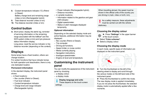 12
12 13
13 14
14 15
15 16
16 17
17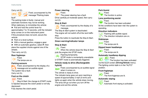 18
18 19
19 20
20 21
21 22
22 23
23 24
24 25
25 26
26 27
27 28
28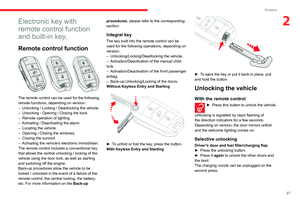 29
29 30
30 31
31 32
32 33
33 34
34 35
35 36
36 37
37 38
38 39
39 40
40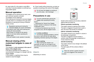 41
41 42
42 43
43 44
44 45
45 46
46 47
47 48
48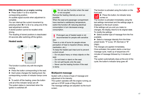 49
49 50
50 51
51 52
52 53
53 54
54 55
55 56
56 57
57 58
58 59
59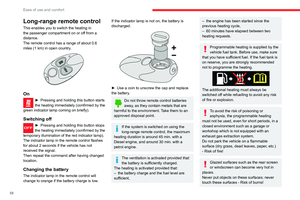 60
60 61
61 62
62 63
63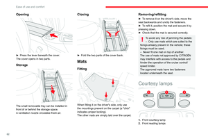 64
64 65
65 66
66 67
67 68
68 69
69 70
70 71
71 72
72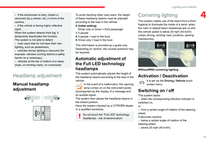 73
73 74
74 75
75 76
76 77
77 78
78 79
79 80
80 81
81 82
82 83
83 84
84 85
85 86
86 87
87 88
88 89
89 90
90 91
91 92
92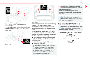 93
93 94
94 95
95 96
96 97
97 98
98 99
99 100
100 101
101 102
102 103
103 104
104 105
105 106
106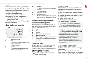 107
107 108
108 109
109 110
110 111
111 112
112 113
113 114
114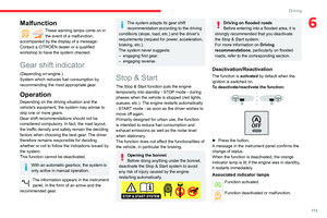 115
115 116
116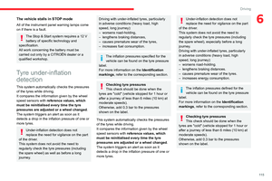 117
117 118
118 119
119 120
120 121
121 122
122 123
123 124
124 125
125 126
126 127
127 128
128 129
129 130
130 131
131 132
132 133
133 134
134 135
135 136
136 137
137 138
138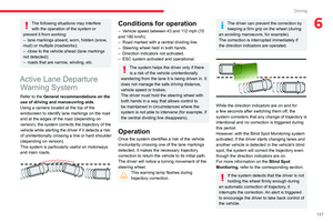 139
139 140
140 141
141 142
142 143
143 144
144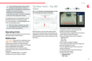 145
145 146
146 147
147 148
148 149
149 150
150 151
151 152
152 153
153 154
154 155
155 156
156 157
157 158
158 159
159 160
160 161
161 162
162 163
163 164
164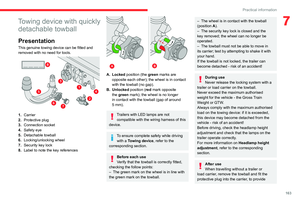 165
165 166
166 167
167 168
168 169
169 170
170 171
171 172
172 173
173 174
174 175
175 176
176 177
177 178
178 179
179 180
180 181
181 182
182 183
183 184
184 185
185 186
186 187
187 188
188 189
189 190
190 191
191 192
192 193
193 194
194 195
195 196
196 197
197 198
198 199
199 200
200 201
201 202
202 203
203 204
204 205
205 206
206 207
207 208
208 209
209 210
210 211
211 212
212 213
213 214
214 215
215 216
216 217
217 218
218 219
219 220
220 221
221 222
222 223
223 224
224 225
225 226
226 227
227 228
228 229
229 230
230 231
231 232
232 233
233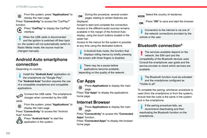 234
234 235
235 236
236 237
237 238
238 239
239 240
240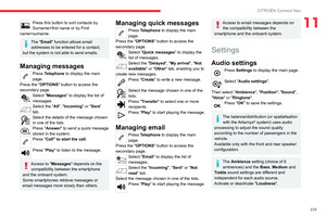 241
241 242
242 243
243 244
244 245
245 246
246 247
247 248
248 249
249 250
250 251
251 252
252 253
253 254
254 255
255 256
256 257
257 258
258 259
259 260
260 261
261 262
262 263
263 264
264 265
265 266
266 267
267 268
268 269
269 270
270 271
271 272
272 273
273 274
274 275
275 159
Practical information
7POWERCHARGE FAULT SymbolDescription
(green)
Connected only to the infrastructure or to the
infrastructure and to the Electric Vehicle (EV) but
no charging in")