2021 RAM PROMASTER CITY transmission
[x] Cancel search: transmissionPage 85 of 280
STARTING AND OPERATING83
RECREATIONAL TOWING (BEHIND MOTORHOME)
Towing This Vehicle Behind Another Vehicle
NOTE:
When towing your vehicle, always follow appli -
cable state and provincial laws. Contact state
and provincial Highway Safety offices for addi -
tional details.
Recreational Towing — Automatic
Transmission
Recreational towing is allowed ONLY if the front
wheels are OFF the ground. This may be
accomplished using a tow dolly or vehicle
trailer. If using a tow dolly, follow this procedure:
1. Properly secure the dolly to the tow vehicle,
following the dolly manufacturer's
instructions.
2. Drive the front wheels onto the tow dolly.
3. Firmly apply the parking brake. Place the transmission in PARK.
4. Properly secure the front wheels to the dolly, following the dolly manufacturer's
instructions.
5. Release the parking brake.
Towing Condition Wheels OFF The Ground Automatic Transmission
Flat Tow NONENOT ALLOWED
Dolly Tow Front
OK
Rear NOT ALLOWED
On Trailer ALLOK
CAUTION!
DO NOT flat tow this vehicle. Damage to the
drivetrain will result. If this vehicle requires
towing, make sure the drive wheels are OFF
the ground.
Towing this vehicle in violation of the above
requirements can cause severe transmis-
sion damage. Damage from improper
towing is not covered under the New
Vehicle Limited Warranty.
4
21_VM_OM_EN_USC_t.book Page 83
Page 87 of 280

STARTING AND OPERATING85
(Continued)
Shallow Standing Water
Although your vehicle is capable of driving
through shallow standing water, consider the
following Cautions and Warnings before doing
so.
WARNING!
Driving through standing water limits your
vehicle’s traction capabilities. Do not
exceed 5 mph (8 km/h) when driving
through standing water.
Driving through standing water limits your
vehicle’s braking capabilities, which
increases stopping distances. Therefore,
after driving through standing water, drive
slowly and lightly press on the brake pedal
several times to dry the brakes.
Failure to follow these warnings may result
in injuries that are serious or fatal to you,
your passengers, and others around you.
CAUTION!
Always check the depth of the standing
water before driving through it. Never drive
through standing water that is deeper than
the bottom of the tire rims mounted on the
vehicle.
Determine the condition of the road or the
path that is under water and if there are any
obstacles in the way before driving through
the standing water.
Do not exceed 5 mph (8 km/h) when
driving through standing water. This will
minimize wave effects.
Driving through standing water may cause
damage to your vehicle’s drivetrain compo -
nents. Always inspect your vehicle’s fluids
(i.e., engine oil, transmission, axle, etc.) for
signs of contamination (i.e., fluid that is
milky or foamy in appearance) after driving
through standing water. Do not continue to
operate the vehicle if any fluid appears
contaminated, as this may result in further
damage. Such damage is not covered by
the New Vehicle Limited Warranty.
Getting water inside your vehicle’s engine
can cause it to lock up and stall out, and
cause serious internal damage to the
engine. Such damage is not covered by the
New Vehicle Limited Warranty.
CAUTION! (Continued)
4
21_VM_OM_EN_USC_t.book Page 85
Page 170 of 280

168SAFETY
Enhanced Accident Response System
In the event of an impact, if the communication
network remains intact, and the power remains
intact, depending on the nature of the event,
the Occupant Restraint Controller (ORC) will
determine whether to have the Enhanced
Accident Response System perform the
following functions:
Cut off fuel to the engine (if equipped)
Cut off battery power to the electric motor (if
equipped)
Flash hazard lights as long as the battery has
power
Turn on the interior lights, which remain on
as long as the battery has power or for
15 minutes from the intervention of the
Enhanced Accident Response System
Unlock the power door locks
Your vehicle may also be designed to perform
any of these other functions in response to the
Enhanced Accident Response System:
Turn off the Fuel Filter Heater, Turn off the
HVAC Blower Motor, Close the HVAC Circula -
tion Door
Cut off battery power to the:
Engine
Electric Motor (if equipped)
Electric Power Steering
Brake booster
Electric park brake
Automatic transmission gear selector
Horn
Front wiper
Headlamp washer pump
NOTE:
After an accident, remember to cycle the igni -
tion to the STOP/OFF position and remove the
key from the ignition switch to avoid draining
the battery. Carefully check the vehicle for fuel
leaks in the engine compartment and on the
ground near the engine compartment and fuel
tank before resetting the system and starting
the engine. If there are no fuel leaks or damage
to the vehicle electrical devices (e.g. headlights)
after an accident, reset the system by following
the procedure described below. If you have any
doubt, contact an authorized dealer.
Enhanced Accident Response System Reset
Procedure
In order to reset the Enhanced Accident
Response System functions after an event, the
ignition switch must be changed from ignition
AVV/START or MAR/RUN to ignition STOP/OFF.
Carefully check the vehicle for fuel leaks in the
engine compartment and on the ground near
the engine compartment and fuel tank before
resetting the system and starting the engine.
After a crash, if the vehicle will not start after
performing the reset procedure, the vehicle
must be towed to an authorized dealer to be
inspected and to have the Enhanced Accident
Response System reset.
21_VM_OM_EN_USC_t.book Page 168
Page 192 of 280

190IN CASE OF EMERGENCY
CavityMaxi Fuse Mini Fuse Description
F0160 Amp Blue –Body Controller
F02 40 Amp Orange –Rear Power Windows, Fog Lamps, Front Heated Seats
(If Equipped)
F02 30 Amp Green –Rear Power Windows, Front Heated Seats (If Equipped)
F02 30 Amp Green –Fog Lamps, Front Heated Seats (If Equipped)
F02 20 Amp Yellow –Front Heated Seats (If Equipped)
F03 20 Amp Yellow –Ignition Switch
F04 40 Amp Orange –BSM System Module
F06 20 Amp Yellow –Radiator Fan - Low Speed
F07 50 Amp Red –Radiator Fan - High Speed
F08 40 Amp Orange –Blower Motor
F10 –15 Amp BlueHorn
F11 –10 Amp RedSecondary Loads ECM
F14 –15 Amp BlueHigh Beam
F15 –15 Amp BlueIP Power Outlet 12 Volt
F16 –5 Amp TanECM and Transmission Shifter
F17 –25 Amp ClearECM Power Loads
F18 –5 Amp TanECM Load, Main Relay
F19 –7.5 Amp Brown Air Conditioning
21_VM_OM_EN_USC_t.book Page 190
Page 199 of 280
IN CASE OF EMERGENCY197
(Continued)
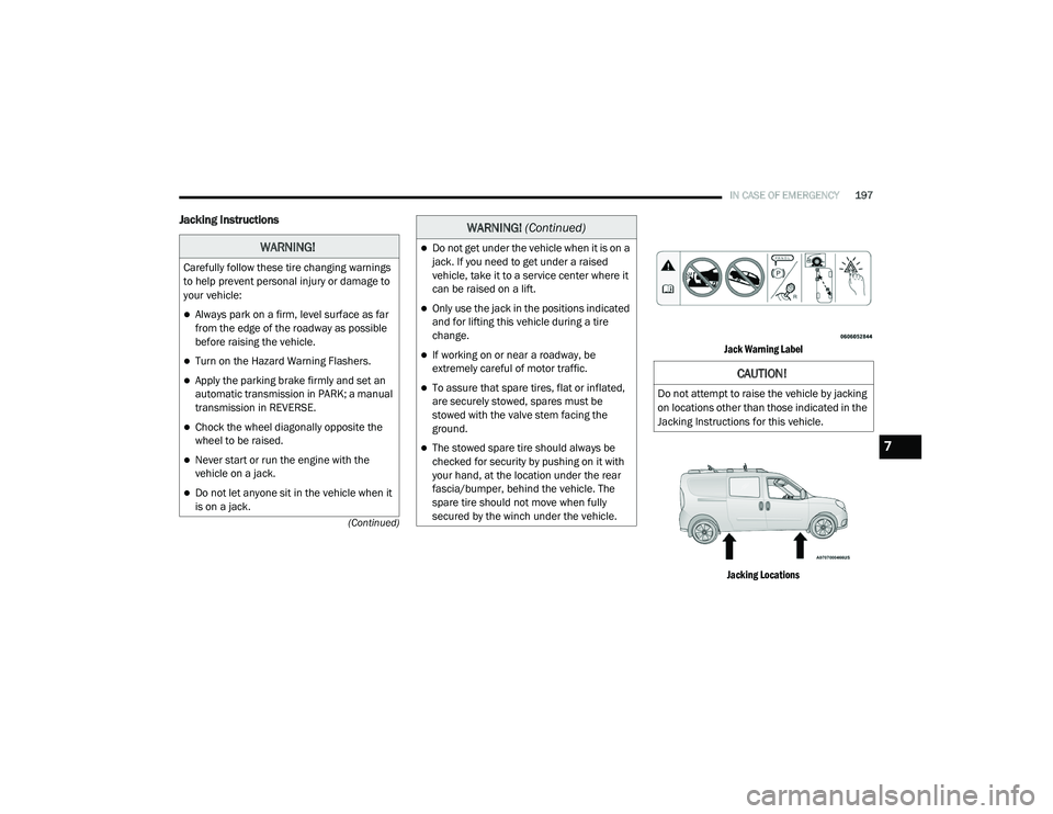
Jacking Instructions
Jack Warning Label Jacking Locations
WARNING!
Carefully follow these tire changing warnings
to help prevent personal injury or damage to
your vehicle:
Always park on a firm, level surface as far
from the edge of the roadway as possible
before raising the vehicle.
Turn on the Hazard Warning Flashers.
Apply the parking brake firmly and set an
automatic transmission in PARK; a manual
transmission in REVERSE.
Chock the wheel diagonally opposite the
wheel to be raised.
Never start or run the engine with the
vehicle on a jack.
Do not let anyone sit in the vehicle when it
is on a jack.
Do not get under the vehicle when it is on a
jack. If you need to get under a raised
vehicle, take it to a service center where it
can be raised on a lift.
Only use the jack in the positions indicated
and for lifting this vehicle during a tire
change.
If working on or near a roadway, be
extremely careful of motor traffic.
To assure that spare tires, flat or inflated,
are securely stowed, spares must be
stowed with the valve stem facing the
ground.
The stowed spare tire should always be
checked for security by pushing on it with
your hand, at the location under the rear
fascia/bumper, behind the vehicle. The
spare tire should not move when fully
secured by the winch under the vehicle.
WARNING! (Continued)
CAUTION!
Do not attempt to raise the vehicle by jacking
on locations other than those indicated in the
Jacking Instructions for this vehicle.
7
21_VM_OM_EN_USC_t.book Page 197
Page 208 of 280
206IN CASE OF EMERGENCY
See below steps to prepare for jump starting:
1. Apply the parking brake, shift the
automatic transmission into PARK (P) and
turn the ignition to STOP.
2. Turn off the heater, radio, and all electrical accessories.
3. If using another vehicle to jump-start the battery, park the vehicle within the jumper
cables reach, apply the parking brake and
make sure the ignition is OFF.
Jump Starting Procedure
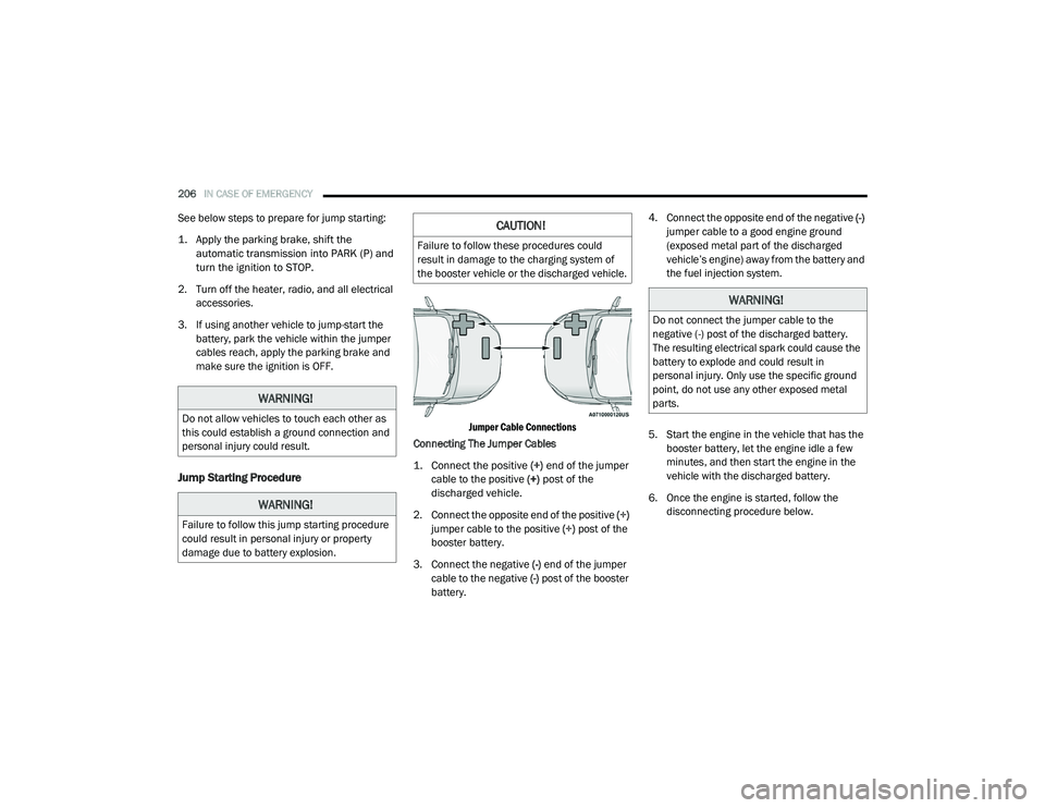
Jumper Cable Connections
Connecting The Jumper Cables
1. Connect the positive
(+) end of the jumper
cable to the positive (+)
post of the
discharged vehicle.
2. Connect the opposite end of the positive (+)
jumper cable to the positive (+) post of the
booster battery.
3. Connect the negative (-) end of the jumper
cable to the negative (-) post of the booster
battery. 4. Connect the opposite end of the negative
(-)
jumper cable to a good engine ground
(exposed metal part of the discharged
vehicle’s engine) away from the battery and
the fuel injection system.
5. Start the engine in the vehicle that has the booster battery, let the engine idle a few
minutes, and then start the engine in the
vehicle with the discharged battery.
6. Once the engine is started, follow the disconnecting procedure below.
WARNING!
Do not allow vehicles to touch each other as
this could establish a ground connection and
personal injury could result.
WARNING!
Failure to follow this jump starting procedure
could result in personal injury or property
damage due to battery explosion.
CAUTION!
Failure to follow these procedures could
result in damage to the charging system of
the booster vehicle or the discharged vehicle.
WARNING!
Do not connect the jumper cable to the
negative (-) post of the discharged battery.
The resulting electrical spark could cause the
battery to explode and could result in
personal injury. Only use the specific ground
point, do not use any other exposed metal
parts.
21_VM_OM_EN_USC_t.book Page 206
Page 210 of 280
208IN CASE OF EMERGENCY
IGNITION KEY REMOVAL OVERRIDE
This vehicle is equipped with a Key Ignition Park
Interlock which requires the transmission to be
in PARK (P) before the ignition switch can be
turned to the OFF/LOCK (key removal) position.
To remove the key manually, proceed as
follows:
1. Firmly apply the parking brake.
2. Remove the Allen Key located in the rear
cargo area, in the tool bag (if equipped) or
on the left side in the cargo box.
3. Unlock the steering column, pull the tilt/ telescoping control handle down. 4. Pull the steering wheel outward until it is in
the end of the travel position, then lock the
steering column in position, push the
control handle up until fully engaged.
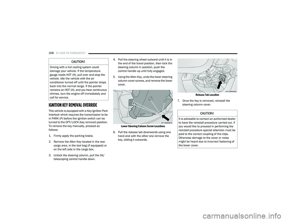
5. Using the Allen Key, undo the lower steering column cover screws, and remove the lower
cover.
Lower Steering Column Screw Locations
6. Pull the release tab downwards using one hand and with the other one remove the
key, sliding it outwards.
Release Tab Location
7. Once the key is removed, reinstall the steering column cover.
CAUTION!
Driving with a hot cooling system could
damage your vehicle. If the temperature
gauge reads HOT (H), pull over and stop the
vehicle. Idle the vehicle with the air
conditioner turned off until the pointer drops
back into the normal range. If the pointer
remains on HOT (H), and you hear continuous
chimes, turn the engine off immediately and
call for service.
CAUTION!
It is advisable to contact an authorized dealer
to have the reinstall procedure carried out. If
you would like to proceed in performing the
reinstall procedure special attention must be
paid to the correct coupling of the clips.
Otherwise damage to the cover or noise
might be heard due to incorrect fastening of
the lower cover.
21_VM_OM_EN_USC_t.book Page 208
Page 211 of 280
IN CASE OF EMERGENCY209
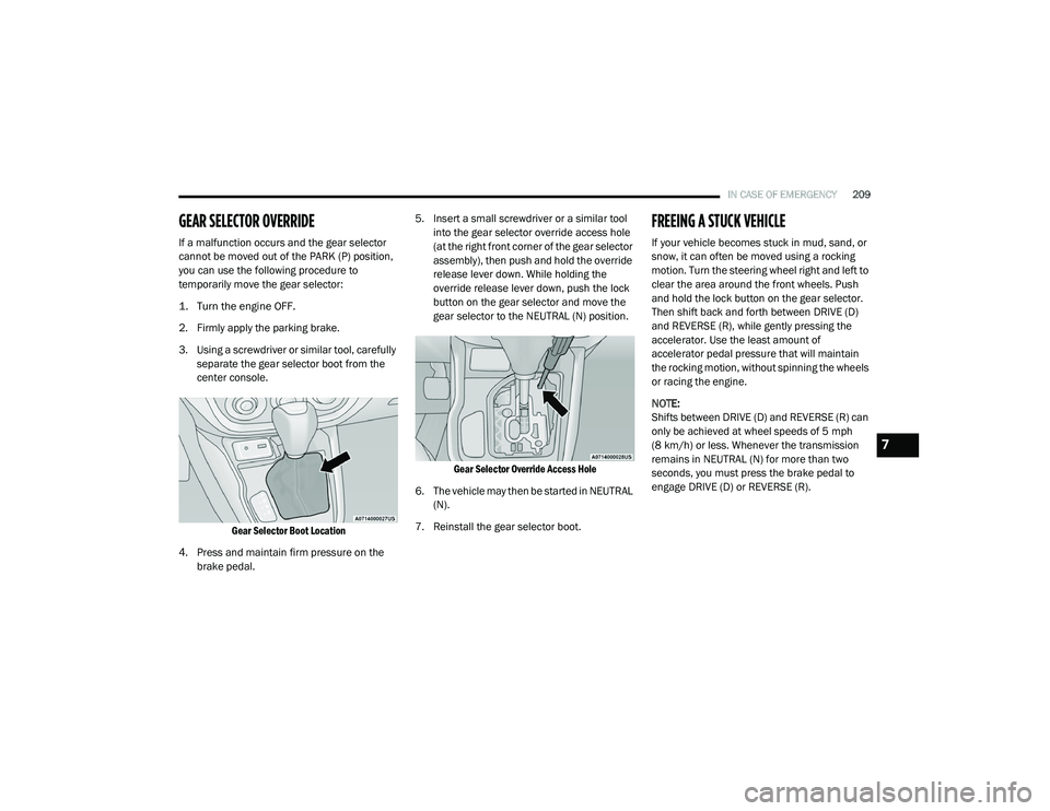
GEAR SELECTOR OVERRIDE
If a malfunction occurs and the gear selector
cannot be moved out of the PARK (P) position,
you can use the following procedure to
temporarily move the gear selector:
1. Turn the engine OFF.
2. Firmly apply the parking brake.
3. Using a screwdriver or similar tool, carefully
separate the gear selector boot from the
center console.
Gear Selector Boot Location
4. Press and maintain firm pressure on the brake pedal. 5. Insert a small screwdriver or a similar tool
into the gear selector override access hole
(at the right front corner of the gear selector
assembly), then push and hold the override
release lever down. While holding the
override release lever down, push the lock
button on the gear selector and move the
gear selector to the NEUTRAL (N) position.
Gear Selector Override Access Hole
6. The vehicle may then be started in NEUTRAL (N).
7. Reinstall the gear selector boot.
FREEING A STUCK VEHICLE
If your vehicle becomes stuck in mud, sand, or
snow, it can often be moved using a rocking
motion. Turn the steering wheel right and left to
clear the area around the front wheels. Push
and hold the lock button on the gear selector.
Then shift back and forth between DRIVE (D)
and REVERSE (R), while gently pressing the
accelerator. Use the least amount of
accelerator pedal pressure that will maintain
the rocking motion, without spinning the wheels
or racing the engine.
NOTE:
Shifts between DRIVE (D) and REVERSE (R) can
only be achieved at wheel speeds of 5 mph
(8 km/h) or less. Whenever the transmission
remains in NEUTRAL (N) for more than two
seconds, you must press the brake pedal to
engage DRIVE (D) or REVERSE (R).
7
21_VM_OM_EN_USC_t.book Page 209